Dampers
–+
123
0
1
–+
12
0
3
0
1
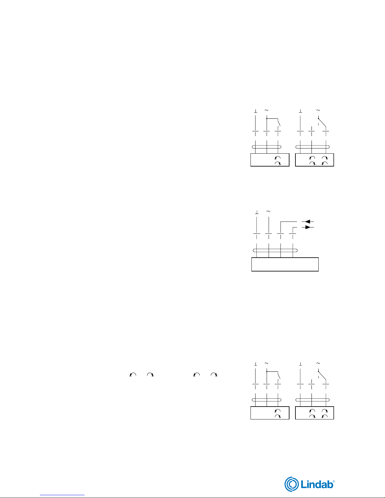
NM 24 A-F NM 230 A-F
Power supply............................. AC 19,2–28,8 V, 50/60 Hz AC 85–265 V, 50/60 Hz
DC 19,2–28,8 V
Power consumption .................. 1,5 W 2,5 W
For wire sizing ........................... 3,5 VA 6 VA
Connection ................................ Cable 1 m, 3×0,75 mm2 Cable 1 m, 3×0,75 mm2
Operating angle......................... Max. 95°, adjustable 0–100% Max. 95°, adjustable 0–100 %
Torque at rated voltage.............. Min. 10 Nm Min. 10 Nm
Direction of rotation................... Switch selectable Switch selectable
0 or 1 0 or 1
Position indication..................... Mechanical Mechanical
Running time for 95° ................. 150 s 150 s
Sound power level..................... Max. 35 dB (A) Max. 35 dB (A)
Protection class......................... III Safety extra-low voltage II Safety insulated
Protection type .......................... IP 54 IP 54
Ambient temperature range ...... -30 to +50°C -30 to +50°C
Ambient moisture ...................... 95 % RH 95 % RH
–+
123
0
1
–+
12
0
3
0
1
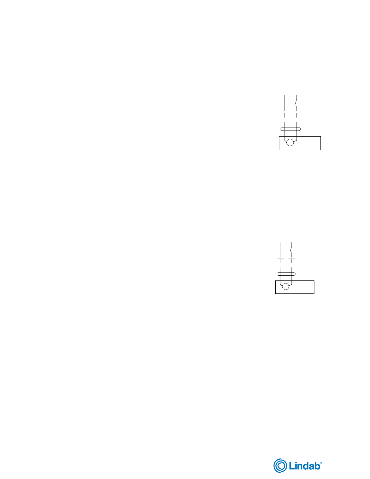
SM 24 A SM 230 A
Power supply............................. AC 19,2–28,8 V, 50/60 Hz AC 85–265 V, 50/60 Hz
DC 19,2–28,8 V
Power consumption .................. 2 W 2,5 W
For wire sizing ........................... 4 VA 6 VA
Connection ................................ Cable 1 m, 3×0,75 mm2 Cable 1 m, 3×0,75 mm2
Operating angle......................... Max. 95°, adjustable 0–100% Max. 95°, adjustable 0–100%
Torque at rated voltage.............. Min. 20 Nm Min. 20 Nm
Direction of rotation................... Switch selectable Switch selectable
0 or 1 0 or 1
Position indication..................... Mechanical Mechanical
Running time for 95° ................. 150 s 150 s
Sound power level..................... Max. 35 dB (A) Max. 35 dB (A)
Protection class......................... III Safety extra-low voltage II Safety insulated
Protection type .......................... IP 54 IP 54
Ambient temperature range ...... -30 to +50°C -30 to +50°C
Ambient moisture ...................... 95 % RH 95 % RH
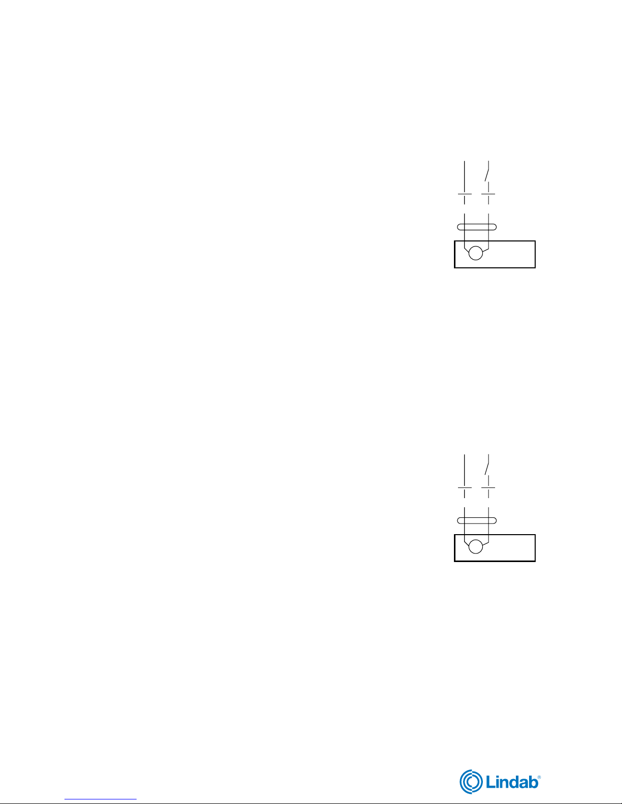
GM 24 A GM 230 A
Power supply............................. AC 19,2–28,8 V, 50/60 Hz AC 85–265 V, 50/60 Hz
DC 19,2–28,8 V
Power consumption .................. 4,5 W 4,5 W
For wire sizing ........................... 7 VA 7 VA
Connection ................................ Cable 1 m, 3×0,75 mm2 Cable 1 m, 3×0,75 mm2
Operating angle......................... Max. 95°, adjustable 0–100% Max. 95°, adjustable 0–100%
Torque at rated voltage.............. Min. 40 Nm Min. 40 Nm
Direction of rotation................... Switch selectable Switch selectable
0 or 1 0 or 1
Position indication..................... Mechanical Mechanical
Running time for 95° ................. 150 s 150 s
Sound power level..................... Max. 45 dB (A) Max. 45 dB (A)
Protection class......................... III Safety extra-low voltage II Safety insulated
Protection type .......................... IP 54 IP 54
Ambient temperature range ...... -30 to +50°C -30 to +50°C
Ambient moisture ...................... 95 % RH 95 % RH
–+
123
0
1
–+
12
0
3
0
1