manuals.online logo
Brands
  1. Home
  2. •
  3. Brands
  4. •
  5. Lindab
  6. •
  7. Controllers
  8. •
  9. Lindab UltraLink FTCU User manual

Lindab UltraLink FTCU User manual

lindab | we simplify construction
Mounting instruction
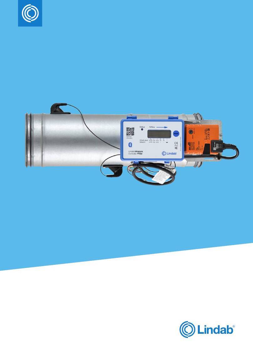
LindabUltraLink®Controller
FTCU
2
Airflow
IP42
Patented
Status
m³/h
l/s
m/s
°C
Mode
Planning
The longer distance to disturbance, i.e. the longer straight
duct before the UltraLink®, the higher the measurement accu-
racy will be. It is not recommended to mount the UltraLink®
so that the first flow sensor (*in the table on the next page) is
placed on an outer radius of a fitting. Never use an UltraLink®
on the outlet side of a duct fan. Place it on the inlet side or in
worst case use a flow conditioner if it must be placed on the
outlet side.
The sensor and the damper bodies can rotate relative to each
other. This means that the sensors can be optimally posi-
tioned independently of the desired position of the display
and damper body. View table on next page for directions on
how to position the sensor body for optimal performance.
Mounting
Position the Controller so that the display is visible from
some direction. For future connections it is important that
the screws on the lid of the display can be removed. Make
sure the airflow arrow is pointing in the direction of the
airflow. Note the ID-number of the monitor. The ID can be
found on the label of the box the monitor was delivered in or
on the label on the monitor and are the three last numbers
of the serial number.
Mount the Controller into the air duct system according to
the mounting instructions for Lindab Safe. Do not use the
flow sensors as handles when you mount the Controller
since they may break and changes in their positions might
influence the measurement accuracy. When the sensor
body is positioned accurately for FTCU of dimension 100—
315 it should be connected with screws to the damper body
in the same way as when you connect ducts and fittings.
FTCU of dimension 400—630 has a flange which needs
to be loosened in order to rotate the sensor and damper
bodies relative to each other. The flange needs to be
tightneded once the bodies are placed correctly.
The Controller can be connected to a RTU (remote termi-
nal unit) via analog or RS485 communication (Modbus). To
be able to connect cords to the terminal board the rubber
cable grommet on the back of the display unit must be
punctured, preferably using an awl or something pointy to
ensure tightness to the environment. When the cords have
been connected they must be strain relieved. The cords
can be attached to the shelf by using cable ties that are
attached around cut outs in the shelf. You must under no
circumstances make any holes or connect anything with
screws to the sensor body since this will have an impact on
measurement accuracy.
3
Disturbance *Placement of first flow sensor
Measurement uncertainty
± % or 1 l/s depending wich is
the greatest
a
2-4·Ød >4-5·Ød >5·Ød
Bend
a
Ød
*
Inner radius 555
Bend
a
Ød
*
Outer radius
(Not recommended) 20 10 5
Bend
a
Ød
*
Side 10 5 5
T-piece
a
Ød
*
Inner radius 10 5 5
T-piece
a
Ød
*
Outer radius
(Not recommended) 20 10 5
T-piece
a
Ød
*
Side 10 5 5
Reducer
a
Ød
*
Duct diameter
decrease 555
Reducer
a
Ød
*
Duct diameter
increase 10 5 5
2019-02-13
www.lindab.com
lindab |we simplify construction
Declaration of incorporation for partly
completed machinery and FCC statement
Ultrasonic device –FTCU
Hereby declares that the partly
completed machinery of the type:
FTCU
are in conformity with the following essential requirements
in Annex 1 of the Machinery directive 2006/42/EC: 1.1.2,
1.1.3, 1.3.4. In addition, the partly completed machinery is
in conformity with all relevant provisions of ordinances in
EMC-Directive 2004/108/EC. The partly complteted
machinery is developed, designed and manufactured with
the essential requirements of the following standards:
EN 61000-6-1:2002 - Part 6-1: Generic standards -
Immunity for residential, commercial and light-industrial
environments
EN 61000-6-2:2005 - Part 6-2: Generic standards -
Immunity for industrial environments
EN 61000-6-3:2002 - Part 6-3: Generic standards -
Emission standard for residential, commercial and light-
industrial environments
EN 61000-6-4:2002 - Part 6-4: Generic standards -
Emission standard for industrial environments
Furthermore, partly completed machinery must not be put
into service until the final machinery into which it is to be
incorporated has been declared in conformity with the
provisions of the Machinery directive 2006/42/EC.
We undertake to transmit, in response to a reasoned
request by the national authorities, relevant information on
the partly completed machinery.
This device complies with Part 15 of the FCC Rules.
Operation is subject to the following two conditions: (1) this
device may not cause harmful interference, and (2) this
device must accept any
interference received, including interference that may
cause undesired operation.
FCC Caution:
Changes or modifications not expressly approved by the
part responsible for compliance could void the user's
authority to operate the equipment.
This equipment complies with FCC exposure limits set forth
for an uncontrolled environment..
FCC Statement:
"This equipment has been tested and found to comply with
the limits for a Class B digital device, pursuant to part 15 of
the FCC Rules. These limits are designed to provide
reasonable protection against harmful interference in a
residential installation. This equipment generates, uses and
can radiate radio frequency energy and, if not installed and
used in accordance with the instructions, may cause
harmful interference to radio communications. However,
there is no guarantee that interference will not occur in a
particular installation. If this equipment does cause harmful
interference to radio or television reception, which can be
determined by turning the equipment off and on, the user is
encouraged to try to correct the interference by one or
more of the following measures:
Reorient or relocate the receiving antenna.
Increase the separation between the equipment
and receiver.
Connect the equipment into an outlet on a circuit
different from that to which the receiver is
connected.
Consult the dealer or an experienced radio/TV
technician for help."
Signed for and on behalf of the manufacturers by:
Authorised person: Karel Kleinmond
Group Operations Director
2019-01-21 Karlovarska, Czech Republic
Company:
Lindab Ventilation AB
Stålhögavägen 115
26982 Båstad
Sweden
Telephone +46 431 85000
www.lindab.com

Other manuals for UltraLink FTCU

4

Other Lindab Controllers manuals

Lindab UltraLink FTCU Manual

Lindab

Lindab UltraLink FTCU Manual

Lindab UltraLink FTCU Manual

Lindab

Lindab UltraLink FTCU Manual

Lindab UltraLink FTCU User guide

Lindab

Lindab UltraLink FTCU User guide

Lindab Regula Combi User manual

Lindab

Lindab Regula Combi User manual

Lindab UltraLink FTCU Manual

Lindab

Lindab UltraLink FTCU Manual

Popular Controllers manuals by other brands

Absen AI BOX 410 user manual

Absen

Absen AI BOX 410 user manual

TCS ISW6031-0145 quick start guide

TCS

TCS ISW6031-0145 quick start guide

Controlli DuraDrive MX40-7 manual

Controlli

Controlli DuraDrive MX40-7 manual

Texas Instruments TMS320C6455 user guide

Texas Instruments

Texas Instruments TMS320C6455 user guide

Prolon PL-C1000-BLR quick start guide

Prolon

Prolon PL-C1000-BLR quick start guide

Oracle Acme Packet 4500 Hardware installation and maintenance guide

Oracle

Oracle Acme Packet 4500 Hardware installation and maintenance guide

LDG RC-100 Operation manual

LDG

LDG RC-100 Operation manual

Lexicon MC-1 Service manual

Lexicon

Lexicon MC-1 Service manual

Bailey infi 90 Modular Power System II Instruction

Bailey

Bailey infi 90 Modular Power System II Instruction

CircuitWerkes DT-232 Technical manual

CircuitWerkes

CircuitWerkes DT-232 Technical manual

Mitsubishi D700 VFD installation guide

Mitsubishi

Mitsubishi D700 VFD installation guide

Badger Meter ER-420-AC user manual

Badger Meter

Badger Meter ER-420-AC user manual

YGE 160 FAI V3 quick start guide

YGE

YGE 160 FAI V3 quick start guide

AWAG Omnio UPJ230/12 manual

AWAG

AWAG Omnio UPJ230/12 manual

Essence Smartcare Care@Home C7000 user guide

Essence Smartcare

Essence Smartcare Care@Home C7000 user guide

Carrier TruVu ChillerVu Installation and startup guide

Carrier

Carrier TruVu ChillerVu Installation and startup guide

METRON FD4 manual

METRON

METRON FD4 manual

MSA Firehawk 10043892 Maintenance and Repair

MSA

MSA Firehawk 10043892 Maintenance and Repair

manuals.online logo
manuals.online logoBrands
  • About & Mission
  • Contact us
  • Privacy Policy
  • Terms and Conditions

Copyright 2025 Manuals.Online. All Rights Reserved.