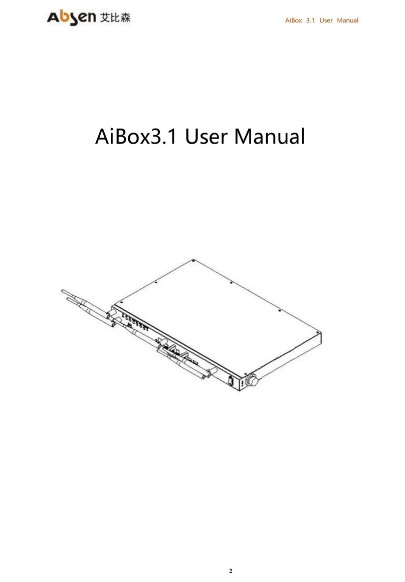
Absen AI BOX 410 User manual

21
AI BOX 410 User manual of the
control box
User Manual version: V 1.0

2.26,2023
catalogue
1. Product introduction....................................................................................................................................................................................... 25
1.1 Attached accessories........................................................................................................................................................................... 25
1.2 Product Overview ................................................................................................................................................................................. 25
.3 1 Product features................................................................................................................................................................................... 25
1.4 Product appearance ............................................................................................................................................................................ 21
1.4.1 Aibox410 (front panel)........................................................................................................................................................... 21
1.4.2 Aibox410 (Rear panel)............................................................................................................................................................ 21
1.5 Product dimension drawing.............................................................................................................................................................. 22
2. Product installation and debugging.......................................................................................................................................................... 22
2.1 Preparation before installation ........................................................................................................................................................ 22
2.2 AI BOX410 (back-mounted version) installation....................................................................................................................... 23
2.2.1 AI BOX410 (back-mounted version) structure installation....................................................................................... 23
2.2.2 Installation of infrared 5P extension line and indicator light board...................................................................... 24
2.3 Connection diagram of the AI BOX400 control box................................................................................................................ 25
2.4 Use the Ai box 410 control box to debug the LED display screen..................................................................................... 26
3. Operation and use of the conference screen system......................................................................................................................... 28
3.1 Boot-up operation............................................................................................................................................................................... 28
3.2 Shutdown operation............................................................................................................................................................................ 30
3.3 Standby operation................................................................................................................................................................................ 31
3.4 Description of the remote control.................................................................................................................................................. 32
3.4.1 Description of the remote control keys........................................................................................................................... 32
3.4.2 Remote control pairing guidance...................................................................................................................................... 32
3.5 Initialization settings............................................................................................................................................................................ 34
3.6 Guidelines for beginners.................................................................................................................................................................... 38
3.6.1 Guide of the remote control................................................................................................................................................ 38
3.6.2 Screen projector guide .......................................................................................................................................................... 30
3.6.3 IO S/MAC screen projection guidance ............................................................................................................................ 30
3.6.4 Software Screen Guidelines.................................................................................................................................................. 31
3.7 Screen projection guidance.............................................................................................................................................................. 31
3.7.1 Wireless screen projection.................................................................................................................................................... 31
3.7.2Android Version of the Transcreen function introduction......................................................................................... 34
3.7.3 Multi-split screen and screen projection........................................................................................................................ 42
3.7.4 The type of screen projection code generation........................................................................................................... 44
3.7.5 Screen projection code setting........................................................................................................................................... 44
3.8 Access to the signal source............................................................................................................................................................... 50
3.8.1 Signal source switching ......................................................................................................................................................... 50
3.8.2, multimedia presentation...................................................................................................................................................... 50
3.8.3, Remote control menu........................................................................................................................................................... 51
3.8.4 Signal source switching of the remote control............................................................................................................. 51
3.9 Display the effect settings ................................................................................................................................................................. 52
3.9.1 Scene mode............................................................................................................................................................................... 52
3.9.2 Custom display effect............................................................................................................................................................. 53
3.9.3 Eye protection mode.............................................................................................................................................................. 53
3.10 Settings .................................................................................................................................................................................................. 54
3.10.1 Network Settings ................................................................................................................................................................... 54
3.10.2 Effect setting............................................................................................................................................................................ 59
3.10.3 Sound Settings ....................................................................................................................................................................... 60
3.10.4 General Settings..................................................................................................................................................................... 61
3.10.5 System Settings...................................................................................................................................................................... 61
3.11 Document management .................................................................................................................................................................65
3.12, Software information....................................................................................................................................................................... 66
3.12.1 Software version .................................................................................................................................................................... 66
3.12.2 Hardware version .................................................................................................................................................................. 66
3.12.3 Firmware upgrade................................................................................................................................................................. 66
4. Dealing with common problems................................................................................................................................................................ 67

23
security information
The following markers are used in this product and manual to mark important safety signals.
warn!
security risk! It may lead to
equipment damage or safety risk
warn!
Read the user manual before
the operation
warn!dangerous voltage! May
cause equipment damage or
electric shock
Warning: Be sure to understand and follow all safety guidelines, safety instructions,
warnings and precautions in this manual.
This product is only used for professionals' operation!
This product may lead to combustion, electric shock and fall.
Read this manual carefully before installing, supplying power, running and
commissioning this product.
Follow the safety instructions on the manual and on the product. If you have any
questions, please ask Absen for help.
Beware of electric shock!
To prevent electric shocks, the equipment must be properly grounded
during installation. Don't ignore the ground plug
The function of the head, otherwise the danger of electric shock will
occur.
In case of lightning, please disconnect the power supply of the
equipment, or provide other applicable lightning protection protection
protect. If the device is not used for a long time, please unplug the
power plug.
Close the main switch during any installation and repair work (e. g.
removing the fuse).
When not using the product, or before disassembling or installing the
product, please disconnect the AC power supply.
AC power used must comply with local building and electrical codes
and must be equipped with overload
And ground fault protection.
The main power switch shall be installed close to the product and at
obvious and easily accessible
square. This can timely disconnect the power supply in case of failure.
Before using this product, check all distribution equipment, cables and
all connections devices
current requirements.

Use the appropriate power cord. Please use appropriate power supply
after budget power and current
Line, and ensure that the power cord is not damaged, aging, damp,
found any overheating phenomenon, please immediately
renewal.
For other questions, please consult with professionals.
Beware of fire!
To avoid fire due to overload of power cable, protect with circuit breaker or fuse.
Maintain good ventilation around the screen, controller, power supply and other
products, at least 0.1 m apart from other items
space.
Do not hang any items on the screen.
Do not modify the product, do not add or subtract parts.
Do not use it at ambient temperatures above 55 ° C.
Beware of injury!
Warning: Manufacturers are not responsible for incorrect, inappropriate, irresponsible,
or unsafe system assembly behavior.
Handle the product
For detailed information on collection, reuse and recycling, please contact the local or
regional waste management unit.
For more details of the environmental performance of our products, please contact us.

25
1. Product introduction
1.1 Attached accessories
Power supply line x1
Mini USB Line, x1
Network cable x1
The HDMI line, x1
Remote control, x1
Antenna x 5
Wireless screen
projector * x 2
* Wireless screen projector is optional and needs to be purchased separately. For details,
please refer to the all-in-one configuration list.
1.2 Product Overview
AI BOX 410 Control box is a 4K ultra HD control box, which is a meeting screen control box
developed based on Android system. It integrates the functions of sending card and Android
system card, and is compatible with OPS Windows function. It supports Windows, Mac OS,
IOS and Android multi-platform terminal wireless screen casting, with up to four screen screen
casting. At the same time, for different conference application scenarios, the four scenarios are
provided, so that the document demonstration, video playback, remote meeting, can match
the best display effect.
.3 1 Product features
⚫Max support for display with 38402160@60Hz resolution (point-to-point display)
⚫5 channels for HDMI 2.0 input (1 for connecting OPS and 1 for pure send mode).
⚫1-way HDMI 2.0 output.

⚫6-way USB interface, used for multimedia material playback and function expansion.
-5 USB2.0 (2 items reserved)
- 1×USB3.0。
⚫The 16-road gigabit network port output.
⚫13.5mm audio output for external audio.
⚫Support the display screen output screen playback.
-The input source of 19201080@60Hz can zoom out to 104104 and zoom in to 28801620.
-The input source of 28402160@60Hz, zoom down to 104104 and zoom up to 40962160.
⚫The customized desktop UI system based on Android can add third-party APP applications.
⚫Support for multi-screen body terminal wireless screen projection.
Including the Windows, Mac OS, IOS, and Android systems. Up to 4 wireless screen display at the
same time.
⚫The terminal APP can realize the wireless screen projection control.
-Mirror reverse control: the speaker reverse controls the LED meeting screen through the terminal.
-Wireless snapshot: Wireless screenshots at any time through the terminal, recording the details of
the meeting.
-Wireless speech: Participants speak directly through the terminal microphone, and the voice can be
wirelessly transmitted to the sound system of the conference screen.
⚫Support for local, online HD video playback.
Support for the HEVC / H.265/H.264 and other mainstream coding formats of 4K ultra HD video
decoding.
⚫Dual WiFi mode.
Wifi morning and wireless hotspots can be opened simultaneously.
⚫Support the picture quality and effect adjustment.
Provide standard, soft, cinema, video 4 scene mode, and can customize the brightness, saturation,
contrast and other parameters.
⚫Support one key to open the eye protection mode.
⚫Support for whiteboard writing and annotation.
⚫Supports Bluetooth 4.0.
Can connect the Bluetooth remote control, Bluetooth mouse, Bluetooth keyboard, Bluetooth audio
and other common peripherals.
⚫Reserve OPS host control interface to realize OPS host switch control.
⚫Compatible with mainstream conference peripherals, including cameras, audio, laser pointer, etc.
⚫HDR function
Support for HDR10-Optima and HLG. Restore the video to express the brightness range and color
space, is the picture is more realistic.
⚫Picture quality engine.
Improve the display effect from the following 3 dimensions (the specific effect is related to the
drive IC):
-Color management: manage the display color gamut to make the display color more accurate.
-Fine gray scale (65536 step by step ash scale calibration): calibrate the 65536 ash scale (16bit) of
the driving IC, optimize the low ash jump, back jump, color deviation, hemp point and other
problems of the display screen, to make the display screen more uniform and delicate.
-22bit +: Increase the gray scale of LED display by 64 times to solve the problem of gray loss in low
light, make the image bright dark details richer and the display effect more delicate.

21
1.4 Product appearance
1.4.1 Aibox410 (front panel)
order
number
Key name
explain
1
Open the key
Control box switch
2
IR
Infrared receiver, can be used for remote control
3
BL +
The LED screen brightness increases
4
BL-
The LED screen brightness is reduced
5
VOL +
The sound of the sound increased
6
VOL-
Sound sound reduction
7
SRC
Signal source switching
8
PWR
Boot / standby
9
LED
Operating status indicator, red indicates control box and
blue indicates normal operation
10
Antenna interface
Up to 5 antennas, including Bluetooth, WiFi, 2.4/5G
wireless hotspot antenna
11
USB 3.0
Used to insert the U disk for multimedia playback and
function expansion
1.4.2 Aibox410 (Rear panel)
Enter the interface
order
number
The
interface
name
quantity
explain
1
AUDIO
1
3.5mm audio output interface, external audio equipment
2
N ET
1
The 100 million abit network port, connect to the PC
communication debugging display screen or access to the
wired network to achieve networking
3
USB 2.0
1
Used to insert the U disk for multimedia playback and

function expansion
4
USB3.0
1
Used to insert the U disk for multimedia playback and
function expansion
5
SPDIF
1
Fiber-optic audio output interface
6
HDMI
3
3-way HDMI 2.0 interface, which can input the HDMI
signal source
7
MINI USB
1
Connect to the PC for the display configuration
8
P OWER
IN
1
220V AC power input, equipment power supply
output interface
9
DATA
16
Gigabit network port output, connect to the LED display
screen,
10
IR
1
Epitaxial infrared receiver terminal interface
1.5 Product dimension drawing
The following figure is the AI BOX400 product size diagram for user reference
2. Product installation and debugging
2.1 Preparation before installation
order
number
name
quantity
explain
unit:mm

23
1
AI BOX410 Control box
1 pcs
a. Back-mounted control box, mount the
guide structure on the back of the screen;
connect the infrared extension cord to the
front bread edge button panel of the
display
b. The cabinet version control box can be
directly installed in the control cabinet and
needs to connect the infrared extension
line to the position of the display screen
2
PC / notebook
(Windows System)
1 pcs
After the installation, after the meeting
screen, use the computer to debug the
LED screen
3
Nova LCT Control software
installation package
1 pcs
NovaLCT V5.3.1 and above
4
LED, the meeting screen
1 pcs
Absenicon Widescreen series
5
AI Box 410 Attached
installation guide rail,
infrared extension line
button panel, installation
screw tools, etc
a
surname
For installation of backmounted panel,
infrared extension and front key panel
6
AI Box 410 Attach wire,
remote control, etc
a
surname
For the hardware wire connection
2.2 AI BOX410 (back-mounted version) installation
2.2.1 AI BOX410 (back-mounted version) structure installation
Install a list of accessories
order
numb
er
Accessories name
qua
ntity
picture
Installation location and
use
1
Touch the bead card
buckle
Two
sets
The buckle holder is
installed on the back-
mounted box, and the
buckle is installed on the
guide rail
2
M 2.5 flat-head
screw
Eigh
t
Fixed touch bead buckle
and buckle holder
3
lead rail
Two
Install on the back of the
box
4
Guide track fixed
screw
Four
Fixed guide rail
5
4mm hexagonal
screwdriver
One
Fixed guide screw

AI BOX400 (Back version) installation steps
step
Absenicon2.0 Conference screen + AI Box
400
Conference screen + AI Box 400
Step 1: Install the
bead holder on the
two guide rails
Note: Place the two rails symmetrically and install the buckle holder on the front of the rail (groove surface).
Step 2: Install the
guide rail on the left
row of the display (on
the back) and the box
in the penultimate
row.
Step 3: Install the
touch bead card on
the back of the AI
BOX400 (back hang)
box
Step 4:
Install the AI BOX400
(back-mounted) box
on the guide rail and
connect it to the
buckle holder.
(Note that after the control box locks in the buckle, lock the guide rail and fix the M8 screw. To test the
smoothness of the guide rail, you can release the guide rail screw to fine-tune the touch bead buckle into the
position.)
2.2.2 Installation of infrared 5P extension line and indicator light board

25
IR 5P extended line x 1pcs
Ired indicator board x 1 pcs
One-key black screen button x 1 pcs
2.3 Connection diagram of the AI BOX410 control box
Infrared
indicator light
board
Power-on /
standby button
And IR 5P
elongation
winding
displacement

Schematic diagram of the control box connection
2.4 Use the Ai box 410 control box to debug the LED display
screen
Step 1 can be connected to the computer through the USB Mini interface or through the network port.
Mode 1: USB connection, connect to the upper computer through the Mini USB port on the AI Box 400.
Method 2: network port connection, through the AI BOX 400 network port.
(The default IP of the control box is 192.168.0.10 when configuring the computer IP. AI BOX400 Control
box supports network port backup, does not support device backup)
1. Connect the upper computer computer through the network port;
2. Right-click the lower right corner of the desktop to open the Network and Sharing Center.
3. Select Local Connection> Properties> Internet Protocol Version (4 TCP / IPv4), to enter the
configuration IP interface.
4. Click "Use the IP address below" to configure the computer IP to the 192.168.0.2~192.168.0.254 network segment,
and click OK.
AI BOX410
Control box

27
Step 2 Run NovaLCT V5.3.1, click "View Device Details" to confirm that the control box is connected, log in>
Synchronize Advanced Login> Display Configuration
Step 3 Set the output resolution of the control box sending card. The output resolution is set to the resolution of
the display screen. After clicking the set, solidify and save
Step 4 Select the display screen connection, complete the M apping of the screen body according to the
arrangement of the LED box and the signal routing, click to send it to the hardware and cure it for storage.

Note: The output port serial number is the output network port number on the control box, and the size of the
receiving card is the display resolution of a single LED box.
3. Operation and use of the conference screen system
3.1 Boot-up operation
Power on the LED meeting screen and the AI Box 400 control box, press the power switch on the AI Box 400 control
box to the "ON" position, the boot button in the lower right corner of the conference screen is red, then press the
PWR button on the AI Box 400 control box or the lower right button of the conference screen panel, or press the
boot / standby button on the remote control, the switch button in the lower right corner of the conference screen
turns blue, the LED meeting screen start and enter the boot screen.

29

3.2 Shutdown operation
When the LED meeting screen is working normally, there are the following two shutdown operation modes.
Mode 1: Press the switch button in the lower right corner of the LED meeting screen panel, and the screen body
shows "Shutdown countdown (5S)" and "Press the shutdown button to cancel" again (the switch button status
indicator is red);
Method 2: press the power button on the remote control, the screen body display "standby (5S)" and "shutdown",
select "shutdown" after the countdown 5S shutdown (switch button status indicator light red);

31
Complete power: Press the power switch on the AI Box 400 control box to OFF.
3.3 Standby operation
In the normal operation of the LED conference screen: press the power button on the remote control, the screen
display "standby (5S)" and "shutdown", select "standby" after countdown 5S standby (switch button status indicator
light blue light);

3.4 Description of the remote control
3.4.1 Description of the remote control keys
3.4.2 Remote control pairing guidance
Way a
Also hold down the sum on the remote control Press the key to pair up;

33
Method 2
1. In the main screen interface of the conference screen system, select "more applications" and enter the APP
application interface;
2. Click "Settings", open the menu interface, select "network —— Bluetooth", and enter the Bluetooth
Settings interface;
3. When the blue indicator on the top of the remote control flashes, select the scanning device in the
Bluetooth Settings
4. Select the device name of "Storm Bluetooth Remote Control" in the device list and match it up.

3.5 Initialization settings
When using the Absen LED meeting screen for the first time, please follow the novice instructions to complete the
initialization setting.
Step 1: Select the language of the meeting screen system, including Chinese, English and Japanese;
Step 2: pair the remote control with Bluetooth, and hold down the "menu button" and "Home page button" on the
remote control;
Table of contents
Other Absen Controllers manuals