6
24V
+B
-A
SH
GND
GND
GND
AO1
AO2
AIN
MO1
MO2
1234 5 678910 11 12
SCL
SDA
GND
3V3
1615
14
13
We reserve the right to make changes without prior notice We reserve the right to make changes without prior notice
Mounting
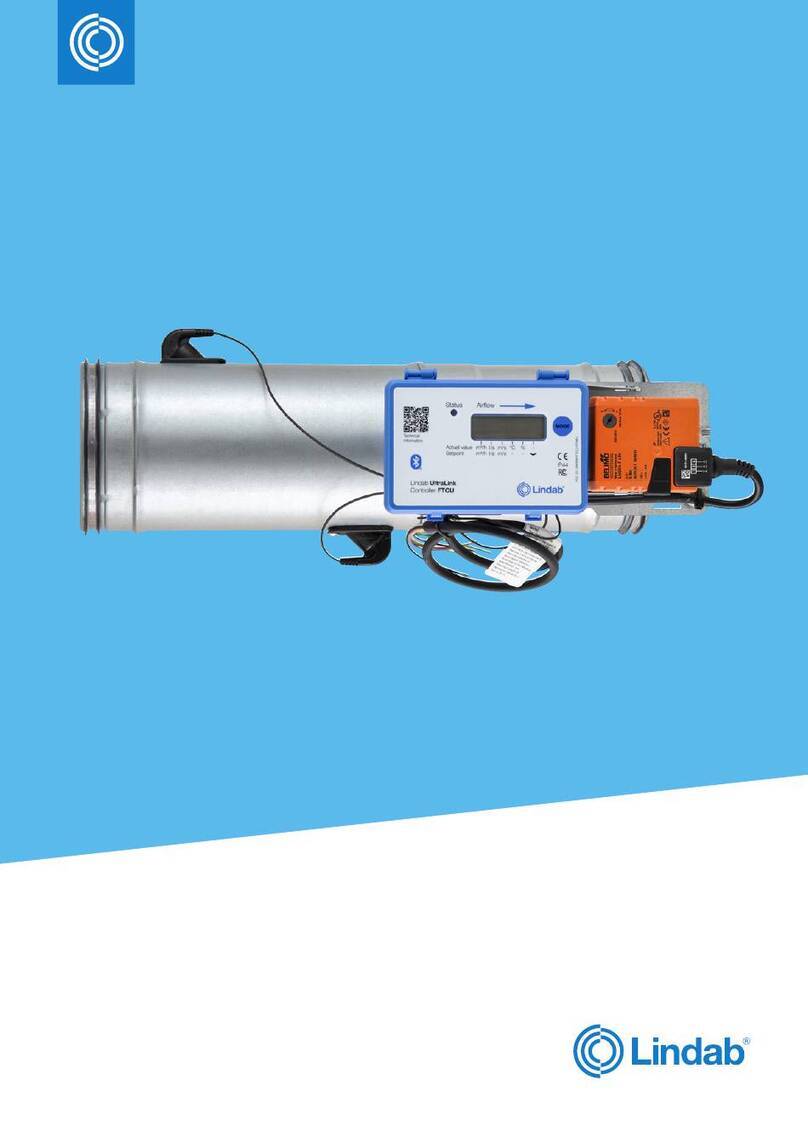
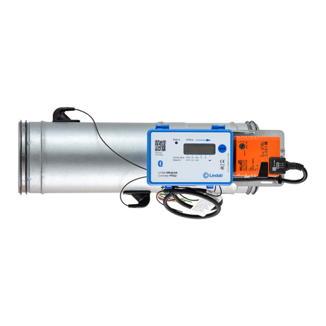
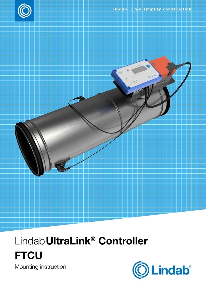
Mount the Controller into the air duct system according to
the mounting instructions for Lindab Safe. Do not use the
flow sensors as handles when you mount the Control-
ler since this may cause damaged and changes in their
positions might influence the measurement accuracy.
Make sure the airflow arrow is pointing in the direction
of the airflow.
Position the damper body so that the display is visible from
some direction. For future connections it is important that
the screws on the lid of the display can be removed.
Note the ID-number of the Controller. The ID can be found
on the label of the box it was delivered in or on the label on
the Controller itself and are the three last numbers of the
serial no.
Rotate the senor body to the correct position according to
the chapter “Planning”, when it is positioned accurately it
should be fixed with screws to the damper body in the same
way as when you connect ducts and fittings. Controllers of
sizes 400 — 630 has a flange which needs to be loosened
by unscrewing a nut. This nut is 10 mm for dimension 400
Connections
Connect the Controller to a remote terminal unit using RS485 or analog terminals. Connections are made in the terminal
board which can be accessed when the lid of the display unit is removed. In the back of the lid there is a picture with a list
of the terminals.
1. 24V, power supply (AC G, DC +) *
2. GND, power supply (AC G0, DC -) *
3. +B, connection for Modbus via RS485
4. -A, connection for Modbus via RS485
5. SH, shield
6. GND, ground (system neutral)
7. AO1, analog output
8. AO2, analog output
9. AIN, analog input
10. MO1, connection for motor
11. MO2, connection for motor
12. GND, ground (system neutral)
13. SCL, not used
14. SDA, not used
15. GND, ground (system neutral)
16. 3V3, not used (in case of biasing)
*) When using AC terminal 1 (G) should have system potential and terminal 2 (G0) should be system neutral.
Recommendations for wiring:
Function Cable type
24 V Supply 2-wire, thickness depending on length and load, max. 1,5 mm²
RS485 2-wire shielded twisted pair, min. 0,1 mm² (LIYCY cable)
Supply the Controller with power from a transformer.
and 13 mm for 500 — 630. By loosening the nut the sensor body can be turned into the desired position. Once this is
achieved, the flange must be fastened by tightening the nut.
To be able to connect cords to the terminal board the rubber cable grommet on the backside of the display unit must be
punctured, preferably using an awl or something pointy to ensure tightness to the environment. When the cords have
been connected they must be strain relieved. The cords can be attached to the shelf by using cable ties that are attached
around cut outs in the shelf.
The display unit and actuator is mounted to enable the Controller to be insulated up to 50 mm.
You must under no circumstances make any holes or connect anything with screws to the sensor body since this will
have an impact on measurement accuracy!


