Lindab InCapsa User guide

Mounting instruction
lindab | we simplify construction
InCapsa

2
lindab | we simplify construction
Description
Lindab InCapsa is a system that makes it easier to assemble, suspend and cover a
ventilation syste
Lindab InCapsa consists of few products that can easily be assembled in different combi-
nations to fit most rooms. In a few steps, you can install and cover a duct system behind
panels of sheet metal.
Lindab InCapsa is suitable for rooms with straight walls and 90° degree corners. In rooms
with different set-ups, e.g. furnished attics, sloping ceilings and curved walls, other solu-
tions should be used.
The system comes in three sizes, Ø100, Ø125 and Ø160, and is compatible with Lindab’s
duct systems.
Advantages of InCapsa
• Everything is fully assembled in one go.
• All work can be carried out by one category of professional.
• Saves both time and money.
• The system is easy to mount and demount.
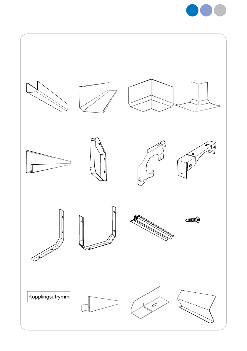
Contents
Components...................................................................................................................... 3
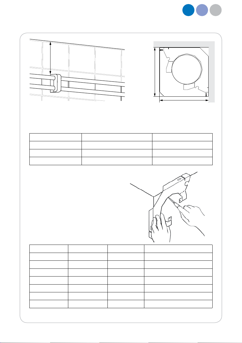
Planning and measurement .............................................................................................. 4
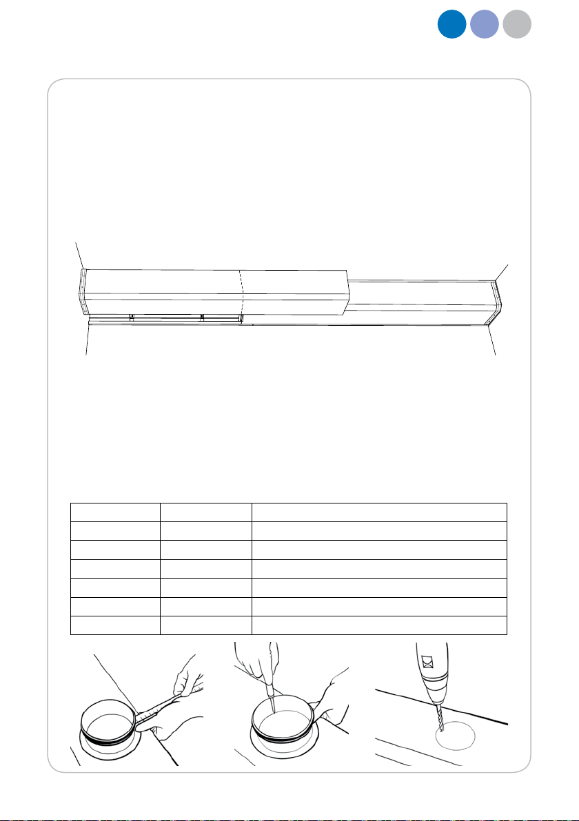
Making holes ..................................................................................................................... 5
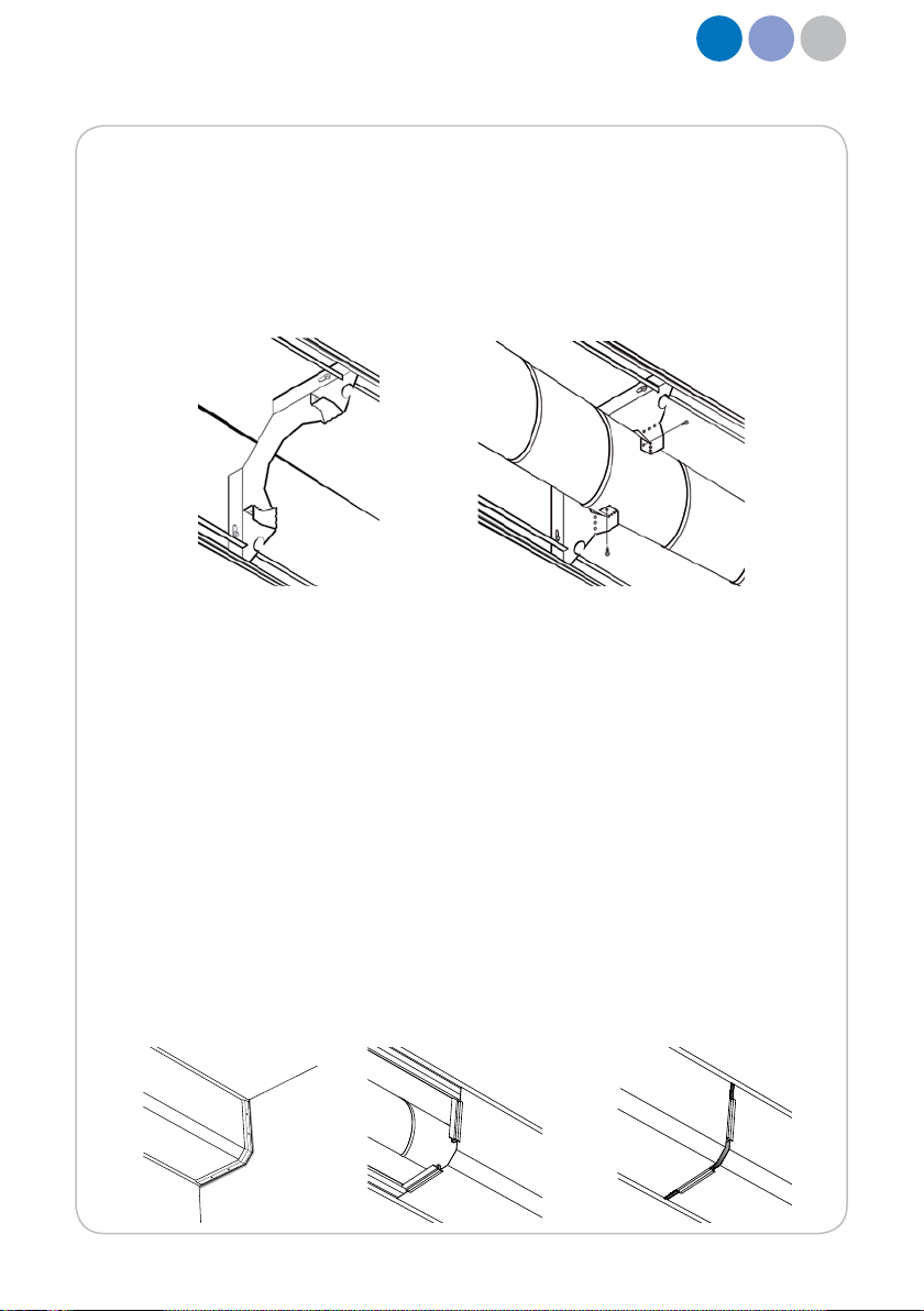
Rails and consoles ............................................................................................................ 6
Support plates....................................................................................................................8
Duct system ...................................................................................................................... 9
Panels and joints................................................................................................................9
Crossing the ceiling..........................................................................................................11
Dimensional transitions....................................................................................................12
Gable................................................................................................................................15
Electrical installations...................................................................................................... 17
Vertical obstacles ............................................................................................................ 18
Touch-up paint ................................................................................................................ 18
Rail alignment plate..........................................................................................................18
Fire................................................................................................................................... 19

3
lindab | we simplify construction
Components
U-panel, CUP Panel, CP Outer corner,
CCO
Inner corner,
CCI
Rail, CSR Gable, CG Console, CC U-console,
CUC
Joint, CPJ U-outer joint,
CPJUO
Inner joint,
CPJI
Joint screw,
FTK
Information
plate, CIP
Access rail,
CACR
Support plate,
CSP
Rail alignment
plate, CSRAP

4
lindab | we simplify construction
Tools you may require
• Drill
• Plugs
• Screws
• Square
• Spirit level
• Marker pen
• Tape measure
• Metal shears
• Nibbler
• Pliers
• Rubber hammer
Other
• Lindab duct system
• Lindab supply and exhaust air valves
Planning and measuring
1. Carefully plan where you intend to mount the duct system in the room.
2. Ideally starting in a corner and letting the rails and panels meet in the centre of the
straight sections.
3.Measure the room and determine how long all rails and panels should be. Remember
that the rail and panel joints should not end in the same place, so try to get them to over-
lap each other in order to create stability.
4. Try to minimise the number of joints on the panels.

5
min.
l
l
lindab | we simplify construction
Making holes
Make a hole through the wall in which the duct is
to be installed. A console of the same dimension
as the duct may be used to find the correct posi-
tion for the hole.
Panel dimension Duct dimension Hole diameter Ceiling to centre of hole
100 100 110 87
125 100 110 107
125 125 135 100
160 100 110 140
160 125 135 136
160 160 170 118
For InCapsa to be installed some space from the ceiling is required. Any obstacles should
be moved or a solution other than InCapsa should be used.
Panel dimension Minimum free heigth to celing Installation length (l)
100 210 201,5
125 240 229
160 280 270,4

6
lindab | we simplify construction
Rails and consoles
Mounting consoles
1. Mark the wall and the ceiling where the consoles are to be attached. The easiest way
to locate the position of the fixing hole is to use a console. Be sure to hold the console
close to both the ceiling and the wall to prevent the installation being skewed.
2. The holes should be positioned as far from the wall and ceiling as the elongated holes in
the console allow. Each rail requires a minimum of two consoles.
3. The first console is attached 300 mm from the wall where the installation begins, with
the next being sited at an appropriate distance to hold both ends of ceiling- and wall
rails.
4. Drill holes in the ceiling and the wall and use suitable plug if necessary. Each console
requires two screws, one in the ceiling and one in the wall.
5. Do not tighten the screws fully; leave them loose so that the console can move and
there is room to insert the upturned edge of the rail into the cut-out slot in the console.
Cutting rails
1. Measure the room carefully and determine how long all rails must be. Mark on the rail
where you need to cut it.
2. Cut the rails to size using metal shears. Start by cutting the portion of the rail folded in
two up to the short side of the rail until you hear a click.
3. Then cut the upturned edge and long side.
4. Bend the rail back and forth on the short side of the rail until it breaks. Straighten the
edge using a pair of pliers if it has become deformed.

7
3 mm
lindab | we simplify construction
Where rails meet in a corner, the edges can be mitred, allowing the joints to line up with
the corners. This produces a more attractive end result than if you let the rails intersect.
To find a 45° angle, the inner corner of the console can be used as a template. Mitred
rails are available if you don’t want to do this job yourself.
Mitring rails in corners
Inner corners
Ceiling rails
One goes towards the wall and the
other is cut where the two meet.
Wall rails
Start from the corner and draw a line
45° into the room on the underside of
the rail. Then draw a line on the folded
part approximately 3mm from the end
of the 45° line in order to ensure that
this does not coincide with the next rail
in the corner. Cut off the folded part.
Then carefully cut along the 45° line,
making sure that this part, which is the
only visible one, fits with the next rail in
the corner.
Outer corners
Ceiling rails
Draw a line on the rail 45° from the
corner out into the room. Start by cut-
ting the upturned edge and long side
of the rail, then cut the folded part.

8
15
lindab | we simplify construction
Wall rails
Start from the corner and let the rail go
15mm out. Draw a line 45° from the
corner out into the room. Then draw a
line on the long side of the rail and the
upturned edge along the corner edge.
Start by cutting the upturned edge and
long side. Then cut off the piece by
cutting along the folded edge. Then cut
along the angled line on the short side.
Mounting rails
1. Start at a wall by placing the first
rail on the wall behind the consoles
and tighten the screws slightly so
that the rail is held in place but can
still be adjusted. Make sure that the
rail is horizontal.
2. Do the same with the correspond-
ing rail on the ceiling. Tighten the
screws. Place the next rail behind
the consoles. Make sure that it is
tight to the previous rail and that
the folds engage with one another.
Tighten the screws and then con-
tinue with the remaining rails.
Support plates
If you need to reinforce the rail attach-
ments, you can use support plates.
Support plates are particularly recom-
mended when attaching rails in a ceil-
ing at an outer corners and where it is
not possible to use consoles.

9
lindab | we simplify construction
Duct system
1. Bend the console’s folding plates so that you can insert the duct system into the con-
soles.
2. Fit the duct system in the consoles and bend back the large tab of the folding plates
so that the duct are held in place. The small tabs of the folding plates can be used to
secure the duct system to the console using self-tapping screws.
Panels and joints
To get a more appealing look, you should consider where the joints between the panels
will be. Try to place joints on equal distant from each other in order to create symmetry.
1. Start at a corner and attach two inner joints to the end of the panel that will be clos-
est to the wall. Screw the outer joint to the inner joints with four joint screws. Hold the
outer joint tight against the panel and start with the two screws furthest from the wall
and ceiling.
2. Secure the panel to the rails by clicking the panel’s folded edge in the ceiling rail’s
fold and then in the wall rail’s fold so that the joint end up against the wall.
3. Attach two inner joints to the free end of the fitted panel.
4. Click subsequent panels into the rails so that one end lies against the inner joints of
the previous panel, remembering to attach the panels correctly from the start since it
is difficult to make lateral adjustments.
5. Attach two inner joints to the other end of the panel and continue attaching panels
until you come to a corner or want to finish the covering of the duct system.

10
lindab | we simplify construction
Holes for duct system
1. On the side of the panel, mark where the hole is to be located.
2. Use a fitting with the same dimension as the duct system inside the panel as a
template. Place the fitting at the correct distance from the top edge of the panel as
shown in the table below and draw the outline of your hole using a marker pen.
3. Drill a 10mm hole about 10mm from the line. Use metal shears and cut a smaller
hole. Then cut the entire hole to the appropriate size, large enough to allow a fitting to
pass through.
Panel dimension Duct dimension Distance from top of the panel to the fitting
100 100 24
125 100 44
125 125 24.5
160 100 77
160 125 61.5
160 160 26
6. Attach two inner joints to the end of the final panel .
7. Hold the final panel between the already attached panel and the wall and mark where it
should lie against the inner joints.
8. Using a square, mark on the panel where you want to cut it and then use the nibbler to
cut. Straighten the edge using a pair of pliers if it has been deformed.
9. Remove the protective film from the panels.
10. In order to make it easy to remove a panel, the inner joints on both sides of the panel
must not be attached to the panel you wish to remove.

11
lindab | we simplify construction
Crossing the ceiling
1. Mount two u-concoles using screws loosesly in the ceiling where the duct is
supposed to be suspended.
2. Place two rails in the concoles slits and make sure that their ends are tight against
the panel or wall. Tighten the screws so that the concels are thight against the ceiling.
3. Suspend the duct system to the u-concoles by using suspension bands.
4. Attach three inner joints to each end of the u-panel.
5. Secure the u-panel to the rails by clicking the panel’s folded edge in the rail’s slit so
that the inner joints are tight against the panel or wall.
6. Hold the u-outer joint tightly pressed against the u-panel and attach it to the inner
joints by using six joint screws.

12
1
2
5
3
4
1 2 3 4 5 6 7
100 100 100 100 TCPU 100 100 110 87
125 100 100 100 TCPMU 100 100 + BU 100 15 110 105
125 100 125 100 TCPU 100 100 110 107
125 125 100 100 TCPMU 125 100 + BU 100 15 110 90
125 125 125 125 TCPU 125 125 135 100
160 100 100 100 TCPMU 100 100 + BU 100 30 110 95
160 125 100 100 TCPMU 125 100 + BU 100 15 110 80
160 125 125 125 TCPMU 125 125 + BU 125 15 135 95
160 160 100 100 TCPMU 160 100 + BU 100 15 135 100
160 160 125 125 TCPMU 160 125 + BU 125 15 135 100
160 160 160 160 TCPU 160 160 170 119
lindab | we simplify construction
Dimensional transitions
1. Panel dimension
2. Duct dimension
3. Panel dimension
4. Duct dimension
5. Transition
6. Hole diameter through wall
7. Distance from ceiling to centre of hole
Perpendicular through wall

13
1
2
3
4
5
1 2 3 4 5
100 100 100 100 -
125 100 100 100 Flexible duct
125 125 100 100 RLU 125 100
125 125 125 100 RLU 125 100
125 125 125 125 -
160 100 100 100 BU 100 15 SR 100 BU 100 15
160 100 125 100 BU 100 15 MF 100 BU 100 15
160 125 100 100 RLU 125 100 MF 100 BU 100 15 SR 100 BU 100 15
160 125 125 100 RLU 125 100 MF 100 BU 100 15 SR 100 BU 100 15
160 160 100 100 RLU 160 100
160 160 125 100 RLU 160 100
160 160 125 125 RLU 160 125
160 160 160 100 RLU 160 100
160 160 160 125 RLU 160 100
160 160 160 160 -
lindab | we simplify construction
Straight through wall
1. Panel dimension
2. Duct dimension
3. Panel dimension
4. Duct dimension
5. Transition

14
1
2
3
4
≈160 mm
lindab | we simplify construction
Panel to u-panel
1. Panel dimension
2. Duct dimension
3. Duct dimension in u-panel
4. Transition
5. Distance from celing to duct suspended in u-panel
6. Hole diameter through panel
7. Distance from ceiling to centre of hole
1 2 3 4 5 6 7
100 100 100 Straight 40 110 88
125 100 100 Straight 50 110 106
125 125 100 Straight 45 110 100
125 125 125 Straight 37 135 100
160 100 100 BU 100 15 + TCPMU 100 100 45 110 105
160 125 100 BU 100 15 + TCPMU 125 100 30 110 105
160 125 125 BU 125 15 + TCPMU 125 125 45 135 102
160 160 100 BU 100 15 + TCPMU 160 100 40 110 80
160 160 125 BU 125 15 + TCPMU 160 125 30 * *
160 160 160 BU 160 15 + TCPMU 160 160 10 * *
* Leave a gap, about 160 mm in the ceiling rails
for the panel, CP, for the transition to fit.

15
lindab | we simplify construction
1. Keep the gable vertically against
the ceiling and wall using a spirit level.
Mark the hole positions. Drill holes and
plug if necessary.
2. Attach the gable tightly against the
ceiling and the wall using screws.
3. Guide the ceiling rail, without the
protective foil, into the gable’s slot. The
rail shold be tight against the gable.
4. Attach a second console loosely
about 100 mm from the end of the rail.
Let the ceiling rail rest in the console’s
slot.
Gable
If the duct system ends in the middle of a wall, you can choose to either let the panels
continue to the next wall or to use a gable.
Lindab recommends finishing at a wall to achieve a more pleasing appearance.

16
17mm
11mm
lindab | we simplify construction
5. Mount the wall rail in the gable and
the console. Attach the second con-
sole tightly against the wall and ceiling.
Gable without outer panel joint,
CPJO
6. Secure the panel to the rails by
clicking the panel’s folded edge in the
ceiling rail’s fold and then in the wall
rail’s fold.
Gable with outer panel joint, CPJO
7. Cut of 11 mm of the gable. Attach
two inner panel joints to the gable.
8. When attaching the panel to the rails
leave a gap of 17 mm to the gabel.
Attach the outer panel joint to the inner
joint by using joint screws, FTK.

17
180mm
lindab | we simplify construction
The consoles’ two Ø16mm holes can be
used to attach plastic conduit pipes. To fit the
pipes in position, either insert the pipes from
the side or bend the metal corners, insert the
pipes and bend back the corners.
If an electrical box cover is covered behind the duct system, fit a slide-in coupling in
front of the cover to make it easier to gain access. If an electrical box cover is concealed
behind the panel, an information plate must be placed on the panel.
Electrical installations
If a rail passes over an electrical box cover, leave a gap by the cover that is as long as
a access rail. Attach the access rail to the panel and make sure it comes off when you
remove the panel to access the electrical box. In order to obtain a neat installation, the
electrical box cover should be no thicker than 3mm.

18
lindab | we simplify construction
Vertical obstacles
If you encounter vertical water pipes, make a hole
measuring about 80×30mm in the panel that bypasses
the pipes. Fit a divisible rubber washer to the surface of
the panel to hide the hole and create a neat installation.
When an electrical cable is routed vertically on the wall,
leave a hole in the wall rail that is 6mm larger than
the diameter of the cable. Seal around the cable using
elastic sealant.
Touch-up paint
If the finish of the panels was damaged during
installation, you can use touch-up paint to con-
ceal the damage.
Rail alignment plate
If two rails don’t align properly it is recommended to place a rail alignment plate inside the
two rails where they meet to make them to align.

19
lindab | we simplify construction
Fire
Each country has is its own fire regulations and they must allways be followed.

1079 EN 2013-11-18
Table of contents
Other Lindab Industrial Equipment manuals
Popular Industrial Equipment manuals by other brands

Zirkon zahn
Zirkon zahn M2 MILLING UNIT COMFORT LINE Operation and maintenance manual

Halma
Halma Ocean Optics DH-3PLUS-CAL Installation and operation manual

Afriso EURO-INDEX
Afriso EURO-INDEX KAV operating instructions

Laguna Tools
Laguna Tools Smartshop SUV manual

Vessel
Vessel IPC-A4 instruction manual

MIYAWAKI
MIYAWAKI ER116 user manual