Linddana TP 160 Installer manual
Linddana A/S • Ølholm Bygade 70 • DK-7160 Tørring • Tel. + 5 7580 5200 • [email protected] • www.tp.dk
User Manual
&
Spare parts catalogue
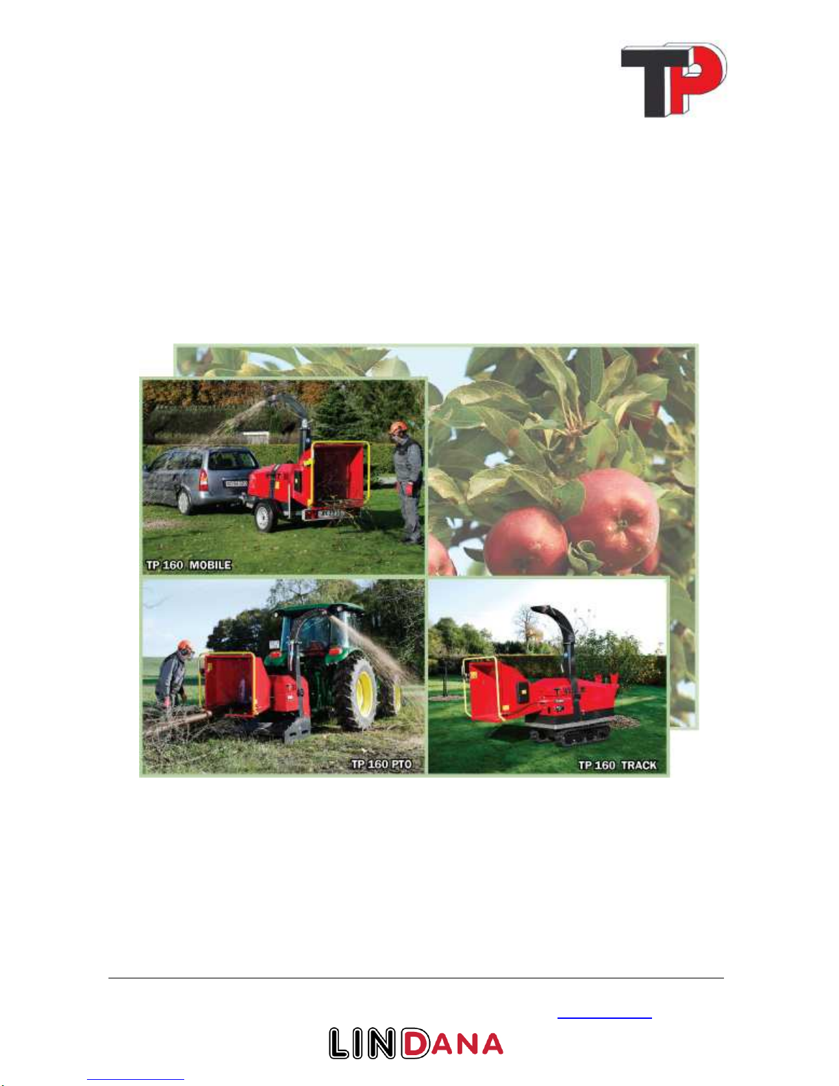
for the TP 160 wood chipper in
the park series

Linddana A/S, Ølholm Bygade 70, DK-7160 Tørring, Telefon +45 75 80 52 00 Fax +45 75 80 54 11
Copyright 2009
2
1Introduction
Congratulations on your new TP wood chipper.
Linddana produces TP wood chippers of the finest quality by using the most modern production
technologies, i.a. laser cutting, CNC technology and robot technology in bright and open production
facilities.
For safety reasons and in order to get maximum pleasure from the wood cutter, it is important to
read these instructions before use.
The user manual explains about safety, use and maintenance so that the work with the wood chipper
will be safe and profitable.
This manual has been translated from Danish.
Linddana A/S
Jørgen Due Jensen, Managing director
Your distributor is always available with spare parts, advice and guidance.
Distributor stamp

Linddana A/S, Ølholm Bygade 70, DK-7160 Tørring, Telefon +45 75 80 52 00 Fax +45 75 80 54 11
Copyright 2009
3
2EU declaration of conformity.
Manufacturer:
LINDDANA A/S, Ølholm Bygade 70, Ølholm, 7160 Tørring, Denmark
hereby declares that
______________________________________________
Wood chipper:
is in concordance with the provisions of the Machine Directive (Directive 06/42/EC) and with the
national legislation which translates this directive;
is in concordance with the following other EC Directives:
2000/14/EC
Furthermore it is stated that
EN 13525 (harmonised standard), has been used.
Title: Managing director
Name: Jørgen Due Jensen
Ølholm, 14 September 2010

Linddana A/S, Ølholm Bygade 70, DK-7160 Tørring, Telefon +45 75 80 52 00 Fax +45 75 80 54 11
Copyright 2009
4
3Table of content
1
Introduction .......................................................................................................2
2
EU declaration of conformity............................................................................3
3
Table of content .................................................................................................4
4
Use......................................................................................................................5
5
Mounting instructions........................................................................................6
6
Safety instructions............................................................................................10
7
Operation of the machine ................................................................................14
8
Maintenance.....................................................................................................16
9
Special instruction for TP 160 MOBILE........................................................26
10
Special instruction for TP 160 TRACK.......................................................30
11
Hydraulics diagram, TP 160 without revolution guard..............................31
12
Hydraulics diagram, TP 160 with revolution guard...................................31
13
Hydraulics diagram, TP 160 TRACK with revolution guard ....................32
14
Instruction for revolution guard TP PILOT 01..........................................33
15
Troubleshooting for wood chipper TP 160..................................................40
16
Guarantee obligation for wood chipper.......................................................41
17
Technical data wood chipper .......................................................................43
18
Accessories....................................................................................................46
19
Spare parts catalogue...................................................................................47

Linddana A/S, Ølholm Bygade 70, DK-7160 Tørring, Telefon +45 75 80 52 00 Fax +45 75 80 54 11
Copyright 2009
5
4Use
The TP 160 wood chipper is designed for stationary wood chipping in the form of braches etc.
The machine must not be used for materials containing stone, metal or other foreign bodies. These
foreign bodies can in the best case dull the knives and in the worst case break the machine. Knives
and anvil can break when stone or metal comes in between them.
The machine must not be used for wood chipping of wood containing nails, screws, arming etc.
When feeding branches you must stand next to the feeding hopper (see fig. 1).
The branches can be thrown around when the retract rollers get a hold of them.
Logs must be fed into the machine from the back (see fig. 2).
Figure 1 Feeding branches Figure 2 Feeding logs
Remember to keep the knives and anvil sharp, it makes feeding easier and gives a better quality
chips, and besides it lovers the use of fuel considerably.
The machine must be inspected daily, meaning the rotor housing must be opened and the rotor,
knives, anvil etc. must be inspected. By doing this you prevent unexpected stops and prolong the life
of the machine.
The tractor or trailer upon which the machine is mounted must always have the brakes activated
during work.
The machine must not:
•Be used for other materials than wood
•Be used to push trees, stubs etc.
There must not be equipment like forest chains, axes, chain saws etc. in the feeding hopper.
Linddana A/S, Ølholm Bygade 70, DK-7160 Tørring, Telefon +45 75 80 52 00 Fax +45 75 80 54 11
Copyright 2009
6
5Mounting instructions
5.1 Before use
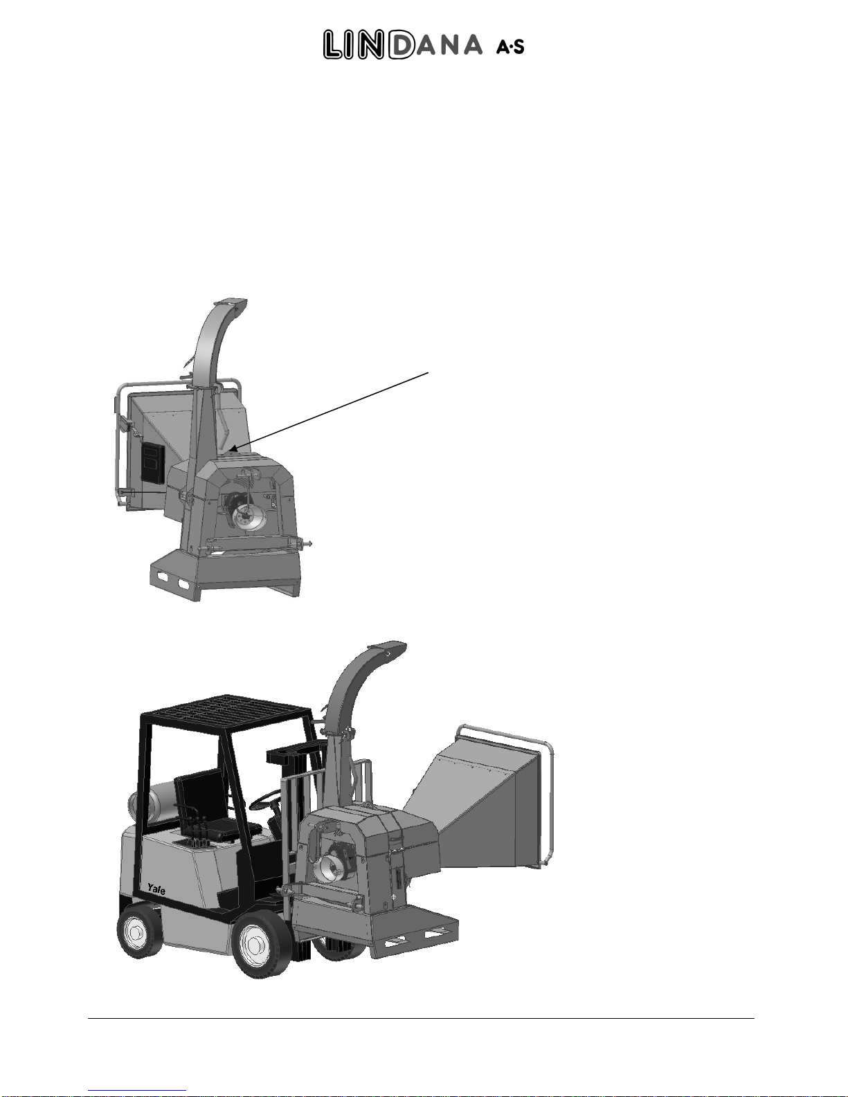
The machine is equipped with a lifting point which is to be used when lifting the machine with a
crane or any other hoisting device (ground assistance) (see Figure 3). The machine can also be lifted
with a fork lift truck. This is done by using the holes made for this purpose on both sides of the foot
(see Figure 4). Make sure that the forks of the truck are put all the way through otherwise the
machine can tip over. The TP 160 MOBILE is mainly transported on the trailer wheels, but it can
also be lifted with a fork lift truck (see Figure 5). The TRACK model can be lifted with a forklift
truck on a pallet. (see Figur 6)
Figure 3 Lifting point on the machine
Figure 4 Lifting with a fork lift truck
Lifting point

Linddana A/S, Ølholm Bygade 70, DK-7160 Tørring, Telefon +45 75 80 52 00 Fax +45 75 80 54 11
Copyright 2009
7
Figure 5 Lifting with a fork lift truck
Figur 6 Lifting with a fork lift
Store the manuals for the PTO member with this manual in the manual box on the machine.
Min. 2 m

Linddana A/S, Ølholm Bygade 70, DK-7160 Tørring, Telefon +45 75 80 52 00 Fax +45 75 80 54 11
Copyright 2009
8
Before operation you must check that the wood chipper cleared of foreign bodies. The machine
must be uncoupled from the tractor’s PTO, for the MOBILE and TRACK models, the key must be
removed from the ignition before opening for the rotor. Check that the rotor is at a complete
standstill. Turn the ejector tube so that it faces the opposite direction of the rotor housing (see fig.
7). Loosen the bolts that hold the upper and lower rotor housing together. Lift the top part of the
rotor housing up until the ejector tube rests on its own. Turn the rotor a few times by hand. Remove
any foreign bodies.
Check that the gap between the knives and the anvil is correct = 0,5 – 0,9 mm. The knives have a
fixed knife position = 10 mm. Check that the knives are not rubbing on the anvils.
Lift the top part of the rotor housing back in place and tighten the bolts.
Check that all bolts, nuts and screws are tightened properly.
Remember to lubricate all the lubrication points (see maintenance schedule, page 16).
Old hydraulics and motor oil and used oil filters and air filters must be handed in at an approved
receiving station.
5.2 Mounting instruction
The machine is designed to be mounted on the tractor’s three-point-suspension or trailer mounted
with its own engine.
Machines for mounting on the tractor’s three-point-suspension is delivered with a PTO axle with
either 1 3/8" - 6 splines or 1 3/8" - 21 splines.
At certain types of tractors a PTO axle with 1 3/8" - 21 splines is used.
The PTO axle must be mounted with free running on the machine side.
Linddana uses Walterscheid W400 with free running which comes with the machine.
The length of the PTO axle has to be adapted to the tractor following instructions from the supplier
of the PTO axle. See the attached manual for the PTO axle.
The machine must stand on a plane, horizontal surface during use and the tractor mounted machines
must be attached to the tractor’s three-point-suspension (see Figure 8). The tractor’s brakes must be
properly activated. Trailer mounted machines must also have their brakes activated (see Figure 9).
When starting the machine: Attachment must be done with the motor running at idle speed or at as
few revolutions as possible in order to avoid overloading of the PTO axle, gear box, tractor and
wood chipper.
Figure 7
Position of ejector tube when
opening rotor housing

Linddana A/S, Ølholm Bygade 70, DK-7160 Tørring, Telefon +45 75 80 52 00 Fax +45 75 80 54 11
Copyright 2009
9
Figure 8 TP 160 PTO three-point-suspension Figure 9 TP 160 MOBILE hand brake
Hand brake
Three-pointsuspension

Linddana A/S, Ølholm Bygade 70, DK-7160 Tørring, Telefon +45 75 80 52 00 Fax +45 75 80 54 11
Copyright 2009
10
6Safety instructions
6.1 Safety regulations
•Use hearing protectors, safety goggles or a similar eye protection, close fitting safety clothing
and safety shoes.
•When working near roads it can be prudent to wear a west which reflects the light to be more
visible to the other road-users. The displaying of signs must be in accordance with the Road
Traffic Act.
•Minimum age for users of the machine is 18, for training and under surveillance from an adult
the age is 16.
•During operation, all body parts must be kept away from the feeding hopper and any
moveable parts of the machine.
•Any material that is stuck between the retract rollers must not be attempted removed by hand
before the spring has been demounted and the roller part opened.
•Always stand next to the feeding hopper during feeding of the machine. Always observe the
terrain conditions around the machine. It can be dangerous to fall near the machine!
•Before starting the machine check that the safety devices are working properly. Especially the
stop and return functions on the operation bow.
•The machine must not be started without the ejector tube mounted to the machine.
•Never use the machine in closed or poorly ventilated spaces, because of the danger of carbon
monoxide poisoning.
•The top part of the machine as well as all other shielding must not be opened/removed before
the rotor disc is completely immovable and the tractor’s motor is stopped.
•Always stop the machine and the tractor during inspections, service or repairs. The machine
must be uncoupled from the tractor’s PTO.
•Tractor mounted machines have to be on the ground before service or repairs are done.
•Always remove the keys from the machine and/or the tractor before leaving it.
•After maintenance and repairs, the machine must not be started before all bolts are tightened
and all safety devices are mounted.
•Three-point mounted machines must be coupled to the tractor’s three-point- suspension
before use.
•The maximum rpm for the machine (1000 rpm) must not be superseded.
•The transmission axle’s tube shielding and covering must always be intact. Safety chains on
the transmission axle have to be properly mounted.
•The length of the PTO axle has to be adapted to the tractor according to the
recommendations from the supplier of the PTO axle.
•The ejector tube must not point towards people or areas where there are people. There is a
safety distance of 20 m. in the direction where the chips are thrown.
•AT DANGER: PUT THE OPERATION BOW IN NEUTRAL (See Figure 11)

Linddana A/S, Ølholm Bygade 70, DK-7160 Tørring, Telefon +45 75 80 52 00 Fax +45 75 80 54 11
Copyright 2009
11
During operation the machine’s height may not supersede 600 mm over the terrain (see fig. 10).
If this height is not maintained the operation/safety handle will not work as it should, and that may
lead to risks of severe personal injury due to retraction.
Figure 10 Maximum height over the terrain
•During transport or when the machine is dismantled, the PTO axle has to be placed in the
machine’s carrier bow.
•In case of transport on roads the ejector tube is turned so it is placed appropriately within the
width of the machine and then it is fixed securely.
•During transport on public roads, the provisions of the authorities must be respected.
•During cleaning of the hopper, THE RETRACT ROLLERS MUST BE STOPPED.
•For cleaning a broom or similar must be used. Never touch the inside of the hopper when the
machine is running.

Linddana A/S, Ølholm Bygade 70, DK-7160 Tørring, Telefon +45 75 80 52 00 Fax +45 75 80 54 11
Copyright 2009
12
6.2 Pictograms used
Warning: Objects thrown!
Safety distance 20m! Warning: Rotating knives!
Wait for rotor to stop! Warning: Rotating rollers!
Warning: Rotating belts! Warning: Danger of retraction!
Do not touch the hopper! Warning: Danger of
retraction!
Do not step on the hopper!
Read the manual before use! Hearing protector and eye
protection prescribed! Lifting point for crane!

Linddana A/S, Ølholm Bygade 70, DK-7160 Tørring, Telefon +45 75 80 52 00 Fax +45 75 80 54 11
Copyright 2009
13
6.3 Noise level
The sound effect level and the sound pressure level from the TP 160 PTO have been measured
during use at 1000 rpm on the rotor disc, powered by a tractor.
The sound effect level and the sound pressure level from the TP 160 MOBILE have been measured
during use at 1000 rpm on the rotor disc, powered by the Lombardini LDW 1404 engine.
The measurements have been conducted according to test provisions
Directive 2000/14/EC, 3. July 2000
EN ISO 3744, 1995
ISO 11201, 1995
ISO 4871, 19. March 1997
EN 13525, 17. February 2005
The guaranteed sound effect level which will be given by the manufacturer according to directive
2000/14/EC are as follows:
TP 160 PTO: 125 dB (A) re.1pW.
TP 160 MOBILE, Lombardini: 123 dB (A) re.1pW.
TP 160 TRACK, Lombardini: 123 dB (A) re.1pW.
The machine’s sound pressure level at the operator’s seat is measured according to ISO 11201 at:
TP 160 PTO: 108 dB (A)
TP 160 MOBILE, Lombardini: 102 dB (A)
TP 160 TRACK, Lombardini: 102 dB (A)
The above mentioned values have the common uncertainty for the method of measuring and the
estimated variation in a product line for the type of machine. Detailed information on the
measurements and results as well as estimation of uncertainty are found in a thorough report which
can be given out on demand.
The sound level is of such a character that hearing protectors are prescribed during use of the
machine.
6.4 Environmental instructions
When changing hydraulic oil or engine oil, oil and used oil filters and air filters must be handed in at
an approved receiving station.
Oil spills must be avoided as much as possible. At oil spills, the spilled oil must be cleaned up and
handed in at an approved receiving station.
Worn out parts must be disposed of for recycling.
When the machine is worn out it must be disposed of properly. Hydraulic oil and engine oil must be
drained and handed in at an approved receiving station with oil filters and air filters.
The rest of the machine must be disposed of for recycling.
Linddana A/S, Ølholm Bygade 70, DK-7160 Tørring, Telefon +45 75 80 52 00 Fax +45 75 80 54 11
Copyright 2009
14
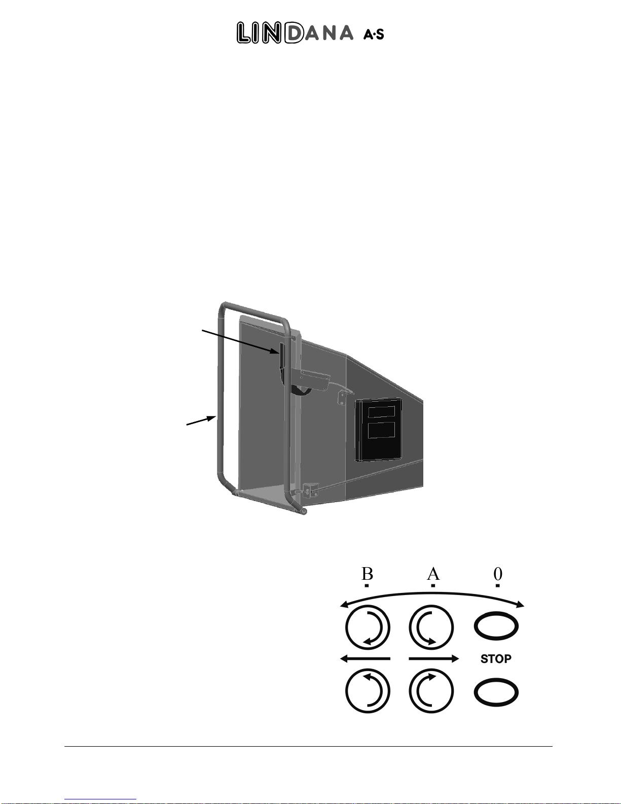
7Operation of the machine
The wood chipper is equipped with two hydraulic rollers, a pressure compensated flow valve, a
control valve and an operation bow with a reset handle (see Figure 11).
The operation bow must be in the stop position (0) during start (see Figure 12). After start you
release the reset handle and pull the operation bow into the middle position (A) and the rollers will
turn. The material is now pulled into the machine.
By pulling the operation bow towards you (B), the flow of oil in the control valve is turned and the
rollers reverse, the material is now pushed out of the machine.
When the machine is either stopped (0) or reversed (B), the reset handle will automatically block the
operation bow. It is now necessary to release the reset handle before the operation bow can be
moved into the middle position (A) and the rollers can pull the material into the machine.
This reset handle is a safety measure so you cannot start the rollers by accident so they pull material
into the machine.
Figure 11
Feeding hopper TP 160 with operation
bow and reset handle
Figure 12
Direction to the operation bow
Operation bow
Reset handle

Linddana A/S, Ølholm Bygade 70, DK-7160 Tørring, Telefon +45 75 80 52 00 Fax +45 75 80 54 11
Copyright 2009
15
By turning the adjusting screw on the flow valve you can find the correct rpm. Never go to fast with
the rollers because the wood will work like a brake if the pressure on the rotor is too big with the
ensuing increase in use of fuel. Branches can get wrapped around the rollers if the rpm is too high.
In the table below (table 1) are stated the recommended rpm on the retract rollers at a desired chip
length. The speeds vary with the number of revolutions on the PTO axle. The chip length can be
regulated on the flow-regulation valve on the wood chipper for smaller chip lengths than indicated in
the table.
7.1 Table 1 Regulating the number of revolutions for the retract rollers
Chip length
Model Rotor
Rpm 4 mm 6 mm 8 mm 10 mm
TP160 1000 15 22 39 36

Linddana A/S, Ølholm Bygade 70, DK-7160 Tørring, Telefon +45 75 80 52 00 Fax +45 75 80 54 11
Copyright 2009
16
8Maintenance
During all maintenance and repairs the machine and the drive must be shut off. Tractor mounted
machines have to be placed on an even surface and be uncoupled from the tractor’s PTO.
8.1 Maintenance schedule
Interval=> hours 8
50
100
200
500
1000
1.000 m
3
10.000 m
3
Lubrication of the PTO axle
1
X
Check of knives and anvil X
Tightening of all nuts and bolts
2
(X)
X
Lubrication of main bearings for rotor
disc
3
X
Tube connection for PTO axle
cleaning/lubrication
4
X
Oil change / Rotate gear
5
X
Lubrication of roller bearings
6
X
Changing of return filter for hydraulic
pump
7
(X) X
Change hydraulic oil
8
X
Anvil turn/change
9
X
Change bow in top rotor housing
10
X
Turn/change triangle and square
scrapers
11
X
Grind flats on retract rollers
12
X
Check V-belts
13
X
Check ejector wings for wear X
Check casing for wear and tear X
1
The PTO axle is dismantled and 4 lubrication nipples are lubricated with Uniway Ep2 or something
of similar quality.
2
Bolts and nuts are tightened, the first time after 8 hours and then with an interval of 50 hours.
3
Two lubrication nipples are lubricated with Uniway Ep2 or something of similar quality.
4
The PTO axle is dismantled and the tube connection is pulled apart, cleaned and lubricated.
5
The oil is changed for the first time after 50 hours, then every 500 hours. Pour W80/90 until it can
be seen in the looking glass, 1.5 l.
6
Two lubrication nipples are lubricated with Uniway Ep2 or something of similar quality.
7
Changed for the first time after 50 hours and then every 1000 hours.
8
The hydraulic oil is drained and new oil is poured on with 20 litres Hydraway HM 32 or something
of similar quality.
9
The anvil is turned/changed depending on need.
10
The bow in the top rotor housing is changed depending on need if it is mounted.
11
The triangle scraper in the rotor housing is turned/changed. The square scraper on the rotor is
turned/changed.
12
The retract rollers are sharpened.
13
The tightening of the V-belts for the pump is checked.

Linddana A/S, Ølholm Bygade 70, DK-7160 Tørring, Telefon +45 75 80 52 00 Fax +45 75 80 54 11
Copyright 2009
17
8.2 Lubrication and oil
As standard, the machine is filled with hydraulic oil on a base of mineral oil with anti-wear additives
which works under boundary lubrication terms at low temperatures i.e. under 60° C. The oil must
meet the following demands:
•Normal working temperature from +30 °C to +60 °C.
•Minimum working temperature -30 °C.
•Maximum working temperature +90 °C.
•In the working temperature area the viscosity should be 35-75 cSt.
•The lowest viscosity allowed is approximately 20 cSt.
The wood chipper is filled with Statoil Hydraway HM 32 from the factory. When changing the oil,
use the same oil or a similar product. Do not mix oils of different types/brands.
The machine has been constructed so you can use biodegradable hydraulic oils with no problems as
long as these oils meet the demands stated above.
Old hydraulic oil and engine oil as well as used oil filters and air filters should be handed in to the
local receiving station.
Lubrication nipples are lubricated according to the maintenance schedule with Statoil Uniway LI62
or a similar product mixed with Uniway LI62.
The machine is equipped with a hydraulic oil tank which is integrated in the rotor housing. The tank
is equipped with a filler neck, an air release valve, a level glass and a return filter.
When changing the hydraulic oil, the filler neck is opened (see Figure 13).
The drain plug is unscrewed. The oil is drained into a canister for proper removal. When the tank is
almost empty, the tank is sucked empty with an oil suction device. The drain plug is screwed back
and new hydraulic oil is slowly filled in (20 litres for TP 160).
Oil is filled in until the level glass is half filled.
Figure 13 Filling hydraulic oil
Filler neck
Level glass

Linddana A/S, Ølholm Bygade 70, DK-7160 Tørring, Telefon +45 75 80 52 00 Fax +45 75 80 54 11
Copyright 2009
18
8.3 Maintenance of the retract rollers
The retract rollers pull the material into the rotor disc and the knives.
The plates on the bottom retract roller must be kept sharp in order to keep the retract force.
This is how it is done:
Stop the machine and the drive. Uncouple the tractor’s PTO. Check that the rotor is at a complete
standstill. Turn the ejector tube so it faces the opposite direction of the rotor housing (Figure 7).
Loosen the bolts which hold the two parts of the rotor housing together and open the rotor housing.
With multigrip pliers or something similar, the spring is lifted off the top retract roller.
Grab the handle and open the roller housing and push the locking pawl into the lock in the side plate
(see Figure 14). The roller housing is now secured from falling down.
Now the flat steels on the bottom retract roller can be grounded with an angle grinder.
Turn the rotor carefully with the operation bow in position forward or reverse. By doing this, the
retract roller is turned so all the plates can be ground.
Remember that the welding seams are not to be ground away.
Figure 14 Securing with locking pawl
When the roller has been grounded, the top retract roller is lowered back in place. The spring is put
back with multigrip pliers. Close the rotor housing and tighten the bolts.
Locking pawl

Linddana A/S, Ølholm Bygade 70, DK-7160 Tørring, Telefon +45 75 80 52 00 Fax +45 75 80 54 11
Copyright 2009
19
8.4 Changing worn parts
8.4.1 Anvil
The anvil in the machine is used as wearing bar for the knife in order to cut the wood. The anvil must
be sharp-edged otherwise the wood will bend down and the cut will become frayed. The machine is
equipped with one horizontal anvil with two edges and one vertical anvil. The vertical anvil can be
turned.
This is how it is done:
Stop the machine and the drive. Uncouple the tractor’s PTO. Check that the rotor is at a complete
standstill. Turn the ejector tube so it faces the opposite direction of the rotor housing (see Figure 7).
Loosen the bolts which hold the two parts of the rotor housing together and open the rotor housing.
With multigrip pliers the spring is lifted off the top retract roller and the roller housing is lifted and
secured with the locking pawl (see Figure 14).
Dismantle the three bolts which hold the horizontal anvil. The anvil is taken out and turned/replaced.
Before the anvil is put back, the anvil and the bearing surface must be cleaned carefully. The distance
between the knife’s edge and the anvil must be 0.5-0.9 mm. (See Figure 15). The tightening factor
for the bolts for the horizontal anvil is 100 Nm / 10 KPm. (Accessory: torque wrench).
Figure 15 Distance between anvil and knife

Linddana A/S, Ølholm Bygade 70, DK-7160 Tørring, Telefon +45 75 80 52 00 Fax +45 75 80 54 11
Copyright 2009
20
The vertical anvil is unscrewed and removed from the inside. Before a new one is put in, the anvil
and the bearing surface must be cleaned carefully. The anvil is set to a distance of 0.5-0.9 mm to the
knives. Use a new precision feeler gauge. The bolts for the vertical anvil are tightened to 50 Nm / 5
KPm. (Accessory: In the tool kit there is a torque wrench).
When the anvils have been turned or replaced and all the bolts are tightened, the roller housing is
lowered with the top retract roller in place. The spring is put back by using multigrip pliers.
Turn the rotor a few times to make sure that there are not any objects in the rotor housing. Close the
rotor housing and tighten the bolts (see Figure 16).
Figure 16 Tighten of bolts in the rotor housing
8.4.2 Knives
The machine is equipped with two knives.
The knives must always be changed in sets. The knives belong together in sets, also when they are
ground so that they are always of equal width. If the knives are not of equal with the rotor will be
out of balance which will lead to unnecessary strain on the bearings and vibrations in the whole
machine.
Bolts which hold the two
parts of the rotor housing
together
This manual suits for next models
3
Table of contents
Other Linddana Chipper manuals


