Linddana TP Series User manual


Linddana A/S . Ølholm Bygade 70 . DK-7160 Tørring . T +45 75 80 52 00 . tp@linddana.com . www.linddana.com
User instructions: TP 230 from 02.11.2015 ©Copyright 2006
2
1Introduction
Congratulations on your new TP wood chipper.
Linddana manufactures top-quality TP wood chippers using the most modern production
technology, including laser-cutting, CNC technology and robot technology, at light, open
production premises.
For safety reasons and in order to gain maximum benefit from your wood chipper, it is essential
to read through the user instructions before using the machine for the first time.
The user instructions explain about safety, use and maintenance, so that work with the wood
chipper can proceed safely and profitably.
This manual has been translated from Danish.
Linddana A/S
Jørgen Due Jensen, director
Your dealer is always available to provide spare parts, useful advice and guidance.
Dealer’s stamp

Linddana A/S . Ølholm Bygade 70 . DK-7160 Tørring . T +45 75 80 52 00 . tp@linddana.com . www.linddana.com
User instructions: TP 230 from 02.11.2015 ©Copyright 2006
3
2EU declaration of conformity.
Manufacturer:
LINDDANA A/S, Ølholm Bygade 70, Ølholm, 7160 Tørring, Denmark
hereby declares that
Wood chipper: ________________________________________________
is in concordance with the provisions of the Machine Directive (Directive 06/42/EF) and with the
national legislation which translates this directive;
is in concordance with the following other EC Directives:
2000/14/EC
Furthermore it is stated that
EN 13525 (harmonised standard), has been used.
Title: Managing director
Name: Jørgen Due Jensen
Ølholm, 02 november 2015

Linddana A/S . Ølholm Bygade 70 . DK-7160 Tørring . T +45 75 80 52 00 . tp@linddana.com . www.linddana.com
User instructions: TP 230 from 02.11.2015 ©Copyright 2006
4
3Table of contents
1Introduction .................................................................................................... 2
2EU declaration of conformity........................................................................... 3
3Table of contents............................................................................................. 4
4Use .................................................................................................................. 5
5Assembly instructions ..................................................................................... 6
5.1 Before initial operation........................................................................................................6
5.2 Coupling instructions ...........................................................................................................7
6Safety instructions........................................................................................... 8
6.1 Safety regulations ................................................................................................................8
6.2 Pictograms used.................................................................................................................10
6.3 Noise level..........................................................................................................................11
6.4 Environmental instructions ...............................................................................................11
7Operation of the machine ............................................................................. 12
7.1 Table 1 Rotation speed settings for feed rollers ...............................................................13
8Maintenance ................................................................................................. 13
8.1 Maintenance schedule.......................................................................................................13
8.2 Lubrication and oil .............................................................................................................14
8.3 Replacing wearing parts.....................................................................................................15
8.4 Sharpening knives ..............................................................................................................23
9User Instructions for TP PILOT 01 .................................................................. 24
9.1 General operation..............................................................................................................24
9.2 Programming .....................................................................................................................26
9.3 Installation .........................................................................................................................30
9.4 Technical data ....................................................................................................................31
10 Troubleshooting for TP 230 wood chipper.................................................. 32
11 Warranty commitment – wood chipper ..................................................... 33
12 Technical data – wood chipper................................................................... 35
13 Hydraulic diagrams .................................................................................... 36
14 Accessories ................................................................................................ 37
15 Spare parts catalogue................................................................................. 37

Linddana A/S . Ølholm Bygade 70 . DK-7160 Tørring . T +45 75 80 52 00 . tp@linddana.com . www.linddana.com
User instructions: TP 230 from 02.11.2015 ©Copyright 2006
5
4Use
The TP 230 wood chipper has been specially designed for stationary wood chipping, in the form of
branches, bushes and wood waste from hedgerows, parks, trees along roads, etc.
Consequently, the machine must not be used for materials containing stone, metal or other
foreign matter. Such foreign matter can, at best, make the knives blunt, and, at worst, break the
machine. Knives and anvils can get broken if stone or metal objects get between them.
The machine must not be used for chipping wood that may contain nails, screws, reinforcement,
etc.
When feeding in branches, you must stand to the side of the feed funnel (See Figure 1).
Branches can whip about when the feed rollers catch them.
When feeding in logs, push these in from the rear (See Figure 2).
Figure 1 Feeding in branches Figure 2 Feeding in logs
Remember to keep knives and anvils sharp; this facilitates feeding and provides better chip
quality. It also reduces fuel consumption.
The machine must be inspected daily, i.e. the rotor housing must be opened and feed mechanism,
rotor, knives, anvils, etc. checked. This protects against unexpected stoppages and ensures a
longer service life for the machine.
The tractor to which the wood chipper is attached must always be secured in a stationary position
during work.
The machine must not:
·be used for any material other than wood
·be used to push over trees, stumps, etc.
Equipment such as choke chains, axes, power saws must not be placed/transported in the feed
funnel.
Linddana A/S . Ølholm Bygade 70 . DK-7160 Tørring . T +45 75 80 52 00 . tp@linddana.com . www.linddana.com
User instructions: TP 230 from 02.11.2015 ©Copyright 2006
6
5Assembly instructions
5.1 Before initial operation
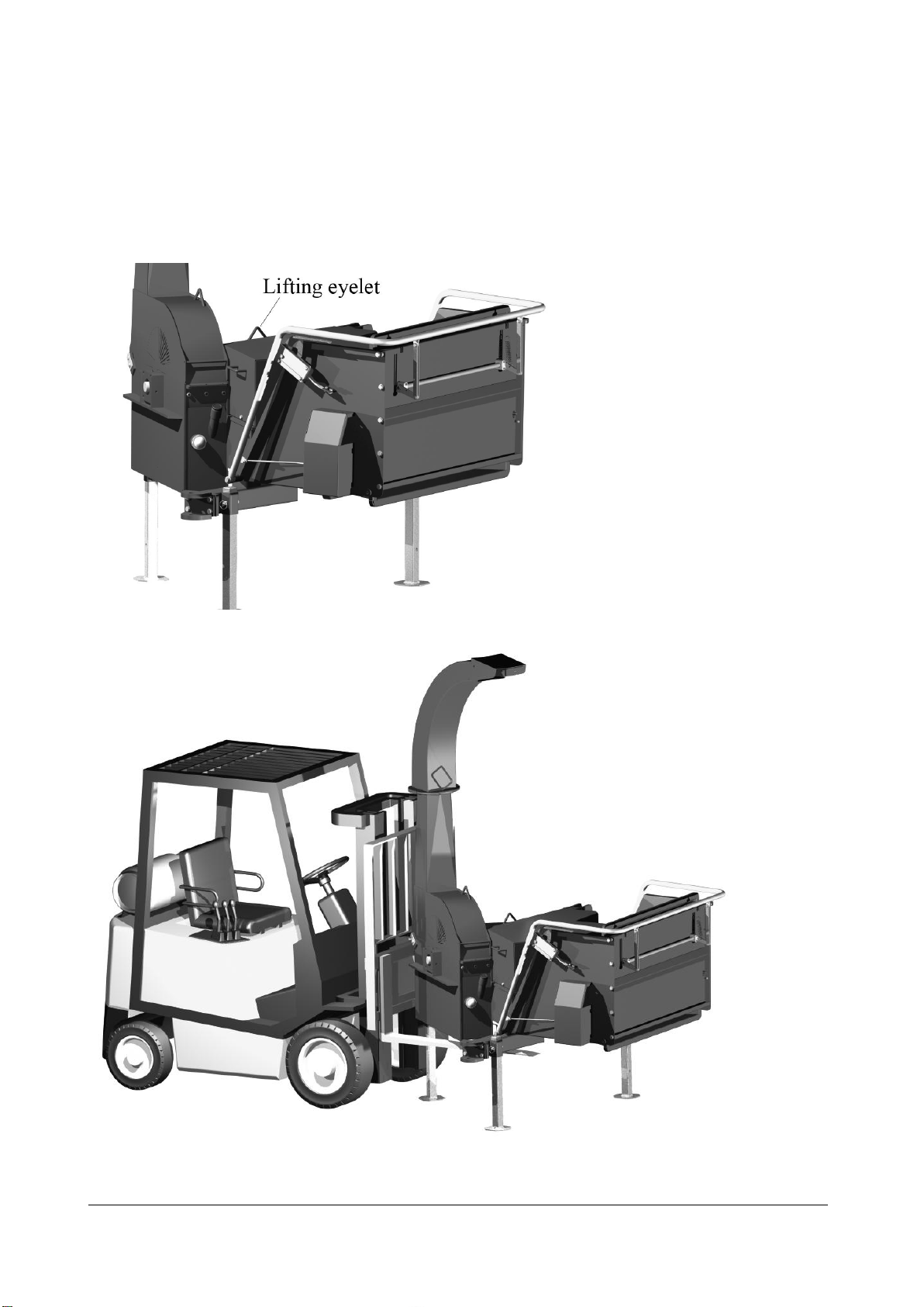
The machine is equipped with a lifting eyelet that can be used when the machine is lifted by crane
or other hoisting device (hoisting). (See Figure 3). The machine can also be lifted using a forklift
truck, but great care must be exercised, as the machine may tip over (See Figure 4).
Figure 3 Lifting eyelet on the machine
Figure 4 Lifting using a forklift truck

Linddana A/S . Ølholm Bygade 70 . DK-7160 Tørring . T +45 75 80 52 00 . tp@linddana.com . www.linddana.com
User instructions: TP 230 from 02.11.2015 ©Copyright 2006
7
Keep user instructions for the PTO shaft together with these user instructions in the special
manual box on the machine.
Before start-up you must check that the wood chipper is free of foreign matter. Loosen the bolts
that hold the upper and lower rotor housing together. Lift up the top part of the rotor housing
until the ejector tube rests in position and turn the rotor several revolutions by hand. Remove any
foreign matter.
Check whether the knives are the correct distance (1 mm) from the anvil. The knife gap is set to
10 mm at the factory. Check whether the knives run free of the anvils.
Lift the top part of the rotor housing into place again and replace the bolts.
Check that all bolts, nuts and screws are properly tightened.
Remember to lubricate all lubrication points (See maintenance schedule on page 13).
Take old hydraulic and motor oil and used oil and air filters to an approved receiving station.
5.2 Coupling instructions
The machine is designed for coupling to a tractor’s three-point hitch.
The factory can supply the machine with a PTO shaft equipped with either 1 3/8" - 6 splines or 1
3/8" - 21 splines
A PTO shaft with 1 3/8" - 6 splines is used on the tractor at 540 rpm. At 1000 rpm, a PTO shaft
with 1 3/8" - 21 splines must be used for some types of tractor.
The PTO shaft must be fitted with free-wheel on the machine side.
Linddana uses Walterscheid 2400 with free-wheel, which accompanies the machine.
The length of the PTO shaft must be adjusted for the tractor according to the instructions from
the supplier of the PTO shaft. See attached user instructions for PTO shaft.
The machine must be standing on firm, level ground when in use. The tractor must be hooked up
to the three-point hitch. The tractor must always be secured in a stationary position.
When starting up the machine: Coupling must be undertaken while idling or with as low a motor
speed as possible, in order to avoid overloading the PTO shaft, gearbox, tractor and wood chipper.
Figur 5
Position of ejector tube
when opening rotor

Linddana A/S . Ølholm Bygade 70 . DK-7160 Tørring . T +45 75 80 52 00 . tp@linddana.com . www.linddana.com
User instructions: TP 230 from 02.11.2015 ©Copyright 2006
8
6Safety instructions
6.1 Safety regulations
·Use hearing protection, safety goggles or equivalent eye protection, close-fitting
protective clothing and safety shoes.
·When working along roads, it is a good idea to wear a reflective vest in order to be more
visible to other road users. Road signs must comply with applicable traffic regulations.
·Minimum permitted age for operating the machine is 18 years, but 16 years when training
under the supervision of an adult.
·Keep all body parts away from the feed funnel and the machine’s moving parts during
operation.
·Always stand to the side of the feed funnel when filling the machine. Always be aware of
the nature of the ground around the machine. Falling over close to the machine can be
dangerous!
·Before starting up, check that the machine’s safety devices
are functioning correctly. This applies in particular to the
operating guard’s stop and return function.
·Never use the machine in enclosed or poorly ventilated
spaces due to danger of carbon monoxide poisoning
·The top part of the machine must not be opened unless
the rotor disc is completely stationary and the tractor’s
motor has stopped.
·Always stop the machine and tractor for any inspections,
servicing and repair work.
·Tractor-mounted machinery must be lowered to the
ground before performing any servicing or repair work
·Always remove ignition keys from the machine and/or
tractor when leaving the machine.
·Following maintenance and repair work, the machine may
only be started once all bolts have been tightened and all safety devices fitted.
·Three-point hitch-mounted machines must be coupled to the tractor’s three-point hitch
before use.
·The machine’s maximum motor speed (1000 rpm) must not be exceeded.
·The PTO shaft shielding and cover must always be intact. Safety chains on the PTO shaft
must be securely fitted.
·The length of the PTO shaft must be adjusted for the tractor according to the instructions
from the supplier of the PTO shaft.
·The ejector tube must not point towards people or areas where people are walking.
·IN THE EVENT OF DANGER: PUT THE OPERATING GUARD IN NEUTRAL
(See Figure 8)
Figur 6 Twocolored shaftend
Linddana A/S . Ølholm Bygade 70 . DK-7160 Tørring . T +45 75 80 52 00 . tp@linddana.com . www.linddana.com
User instructions: TP 230 from 02.11.2015 ©Copyright 2006
9
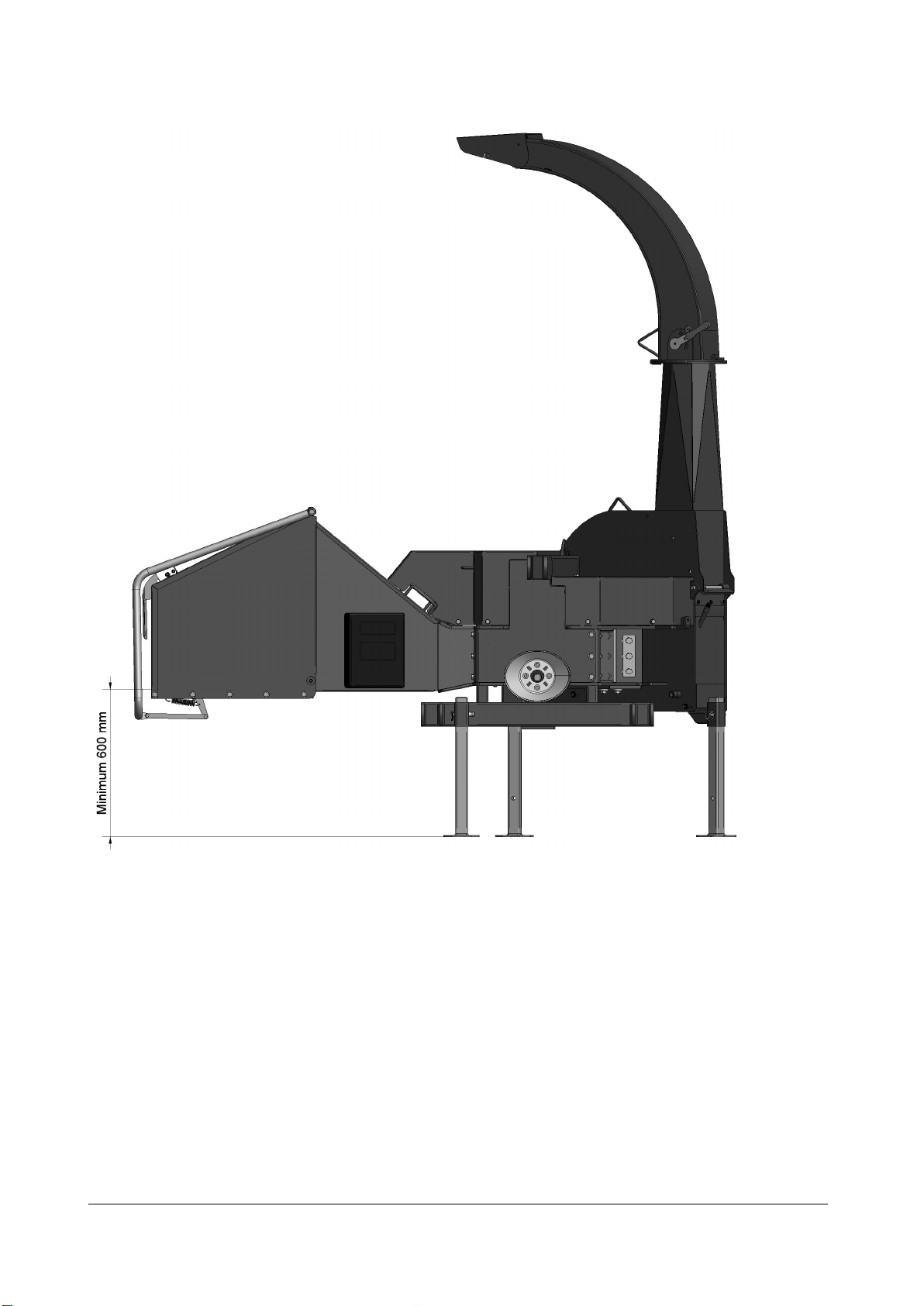
·During operation set the machine’s height to at least 600 mm above the ground (Figure 7).
Figure 7 Minimum height above the ground
·During transport or when dismantled, place the PTO shaft in the machine’s shaft holder.
·In case of transport on roads the ejector tube is turned so it is placed appropriately within
the width of the machine and then it is fixed securely.For transport on public roads, official
regulations must be obeyed.
·The machine is equipped with a tilting funnel; this must be tipped up and secured with
split pins during transport.
·When cleaning small chips from the base of the funnel, THE FEED ROLLERS MUST BE
STOPPED.
·A brush or similar item must be used for cleaning. Never touch the inside of the funnel
when the machine is in operation.
Linddana A/S . Ølholm Bygade 70 . DK-7160 Tørring . T +45 75 80 52 00 . tp@linddana.com . www.linddana.com
User instructions: TP 230 from 02.11.2015 ©Copyright 2006
10
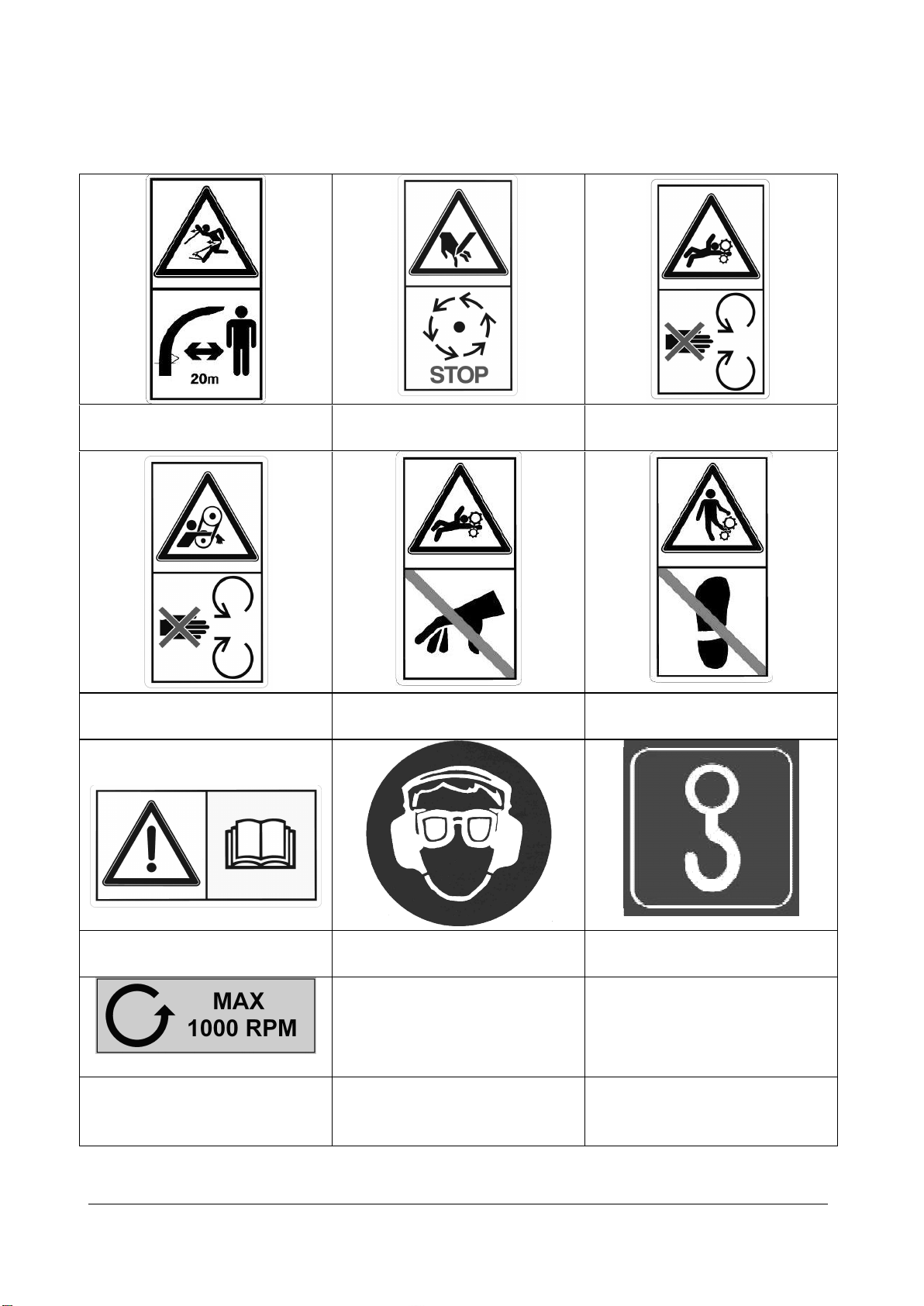
6.2 Pictograms used
Warning: Objects thrown!
Safety distance 20m!
Warning: Rotating knives!
Wait for rotor to stop!
Warning: Rotating rollers!
Warning: Rotating belts! Warning: Danger of retraction!
Do not touch the hopper!
Warning: Danger of retraction!
Do not step on the hopper!
Read the manual before use! Hearing protector and eye
protection prescribed!
Lifting point for crane!
Warning: Max 1000 rpm, anti-
clockwise direction of
rotation!

Linddana A/S . Ølholm Bygade 70 . DK-7160 Tørring . T +45 75 80 52 00 . tp@linddana.com . www.linddana.com
User instructions: TP 230 from 02.11.2015 ©Copyright 2006
11
6.3 Noise level
The sound power level from the wood chipper has been measured during operation at 1000 rpm
on the rotor disc, powered by a tractor.
The measurements were performed according to testing regulations
Directive 2000/14/EC, 3 July 2000
EN ISO 3744, 1995
ISO 11094, December 1993
ISO 4871, 19 March 1997
The warrantyd sound power level that must be disclosed by the manufacturer pursuant to
directive 2000/14/EC is as follows:
TP 230 wood chipper: 123 dB (A) re.1pW.
The above values take into account the common uncertainty of the measurement method and
the estimated variation in a product range for the machine type. Detailed information on
measurements and results and estimation of uncertainty can be found in an in-depth report,
supplied on request.
The sound level is such that hearing protection is mandatory during use.
6.4 Environmental instructions
When replacing hydraulic or motor oil, dispose of oil and oil and air filters in a responsible
manner; take to an approved receiving station.
Oil spills must be avoided as far as possible. In the event of a spillage, the spilled oil must be
cleaned up and taken to an approved receiving station.
Take worn-out parts for recycling.
When the machine is no longer functional, it must be disposed of responsibly. Hydraulic and
motor oil must be drained and taken to an approved receiving station together with oil and air
filters.
Take the rest of the machine for recycling of the materials.
Linddana A/S . Ølholm Bygade 70 . DK-7160 Tørring . T +45 75 80 52 00 . tp@linddana.com . www.linddana.com
User instructions: TP 230 from 02.11.2015 ©Copyright 2006
12
7Operation of the machine
The wood chipper is equipped with two hydraulic rollers, pressure-compensated flow valve,
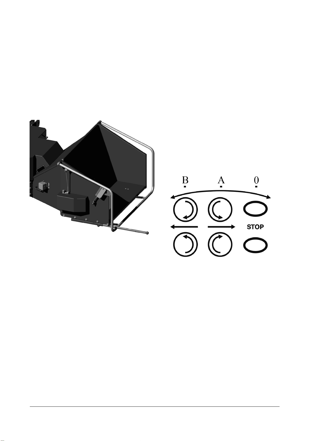
control valve and operating guard on the feed funnel (See Figure 6). The feed funnel can be tilted.
The operating guard must be in the stop position (0) during start-up (See Figure 7). After start-up,
pull the operating guard to the central position (A) and the rollers will turn. The material will now
be drawn into the machine.
Drawing the operating guard all the way towards you (B) will reverse the oil flow in the control
valve, reverse the rollers, and the material will now run out of the machine.
Figure 8 Feed funnel TP 230 with operating
guard
Figure 9 Directions for the operatin
By adjusting the adjusting screw on the flow valve, you can determine the correct rotation speed.
Never run the rollers too fast, as the wood, together with too much pressure on the rotor, will act
as a brake, resulting in increased fuel consumption. Branches can wind around the rollers if the
rotation speed of the rollers is too fast.
The table below (Table 1) shows the recommended rotation speeds of the feed rollers for the
required chip length. The speed varies with the rotation speed of the PTO shaft. The chip length
can be regulated using the wood chipper’s flow regulation valve for chip lengths smaller than
specified in the table.

Linddana A/S . Ølholm Bygade 70 . DK-7160 Tørring . T +45 75 80 52 00 . tp@linddana.com . www.linddana.com
Brugsanvisning: TP 230 fra dato 02.11.2015 ©Copyright 2008
13
7.1 Table 1 Rotation speed settings for feed rollers
8Maintenance
The machine and any power must be stopped for all maintenance and repair work. Tractor-
mounted machinery must be positioned on firm, level ground.
8.1 Maintenance schedule
Interval=> hours 8 6
50 6100
6
200
6
1000 61.000 m3 10.000 m3
Lubricate PTO shaft1X
Check knives and anvil X
Tighten all bolts and nuts2(X) X
Lubricate main bearings for rotor disc3X
Clean/lubricate PTO shaft pipe
connection4
X
Lubricate roller bearings5X
Replace return filter for hydraulic pump6(X) X
Change hydraulic oil7X
Turn/replace anvil8X
Change guard in top rotor housing9X
Turn/replace triangular and square
scrapers10
X
Sharpen flat steel on feed rollers11 X
Check V-belts12 X
Oil change turning gear13 X X
Check ejector blades for wear X
Check casing for wear X
1Remove the PTO shaft and lubricate 4 lubricating nipples with Uniway Li62.
2Tighten bolts and nuts, first time after 8 hours and then at 50-hour intervals.
3Lubricate two lubricating nipples with Uniway Li62.
4Remove PTO shaft and draw the pipe connections apart, clean and lubricate.
5Lubricate two lubricating nipples with Uniway Li62.
6Replace first time after 50 hours and then after every 1000 hours.
7Drain the hydraulic oil and fill with new oil using 21 litres of Hydraway HVXA 46 or oil that has the
equivalent specifications. The interval between changing oil can be extended by using biodegradable
hydraulic oil, such as the type Hydraway SE 46 HP and taking oil samples on an ongoing basis.
8Turn/replace anvil.
9Change guard in top rotor housing, if fitted.
10 Turn/replace triangular scraper in rotor housing. Turn/replace square scraper on rotor.
11 Sharpen feed rollers.
12 Check tension of V-belts
13 The first oil change should be effected after the first 50 working hours, subsequently changes should
take place after 500-800 hours or at least once a year. Pour 1,2 l SAE90EP, or similar oil quality, in the
upper part of the gear, and 1,7 l in the lower.
TP 230 (3 knives)
Knife gap
1000
rpm
theoretical
m/min
theoretical
m/min
Chip length
mm
12 81 53 29 18
10 67 44 24 15
8 54 35 19 12
Linddana A/S . Ølholm Bygade 70 . DK-7160 Tørring . T +45 75 80 52 00 . tp@linddana.com . www.linddana.com
Brugsanvisning: TP 230 fra dato 02.11.2015 ©Copyright 2008
14
Figure 11 How to lift off the spring
8.2 Lubrication and oil
The Wood Chipper is as standard, factory-filled with hydraulic oil of the type Hydraway HVXA 46.
When replacing the oil, use the same type of oil or oil with equivalent specifications. Do not mix
together different types/brands of oils.
As an accessory, the Wood Chipper can be delivered factory-filled with biodegradable oil of the
type saturated ester, Hydraway SE 46HP. When replacing the oil, use the same type of oil or oil
with equivalent specifications. Do not mix together different types/brands of oils.
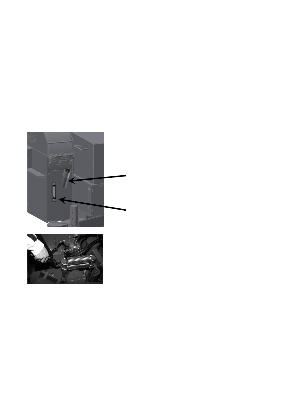
When replacing the hydraulic oil, open the filling nozzle (see Figure 8).
Unscrew the drain plug. Collect the oil in a container for proper disposal. Once the tank is empty,
use oil suction equipment to suck the tank totally dry. Screw the drain plug back in and fill slowly
with new hydraulic oil (21 litres for TP 230).
Fill until the oil reaches the midpoint of the sight glass.
Figure 10 Filling with hydraulic oil
Filling nozzle
Sight glas
Linddana A/S . Ølholm Bygade 70 . DK-7160 Tørring . T +45 75 80 52 00 . tp@linddana.com . www.linddana.com
Brugsanvisning: TP 230 fra dato 02.11.2015 ©Copyright 2008
15
8.3 Replacing wearing parts
8.3.1 Anvil
The anvil in the machine is used as a bedplate for the knives to cut the wood. The anvil must have
sharp edges, as otherwise the wood will bend and the cut edge will be frayed. The machine is
equipped with one horizontal anvil with two reversible cutting edges and one vertical anvil with
four reversible cutting edges.
What to do:
Stop the machine and turn off any power. Remove the screen above the revolving roller. Loosen
the bolts holding the two sections of the rotor housing together and open the rotor housing.
Using multigrip pliers lift the two springs off the revolving feed roller and pull the roller to the side
(See Figure 11).
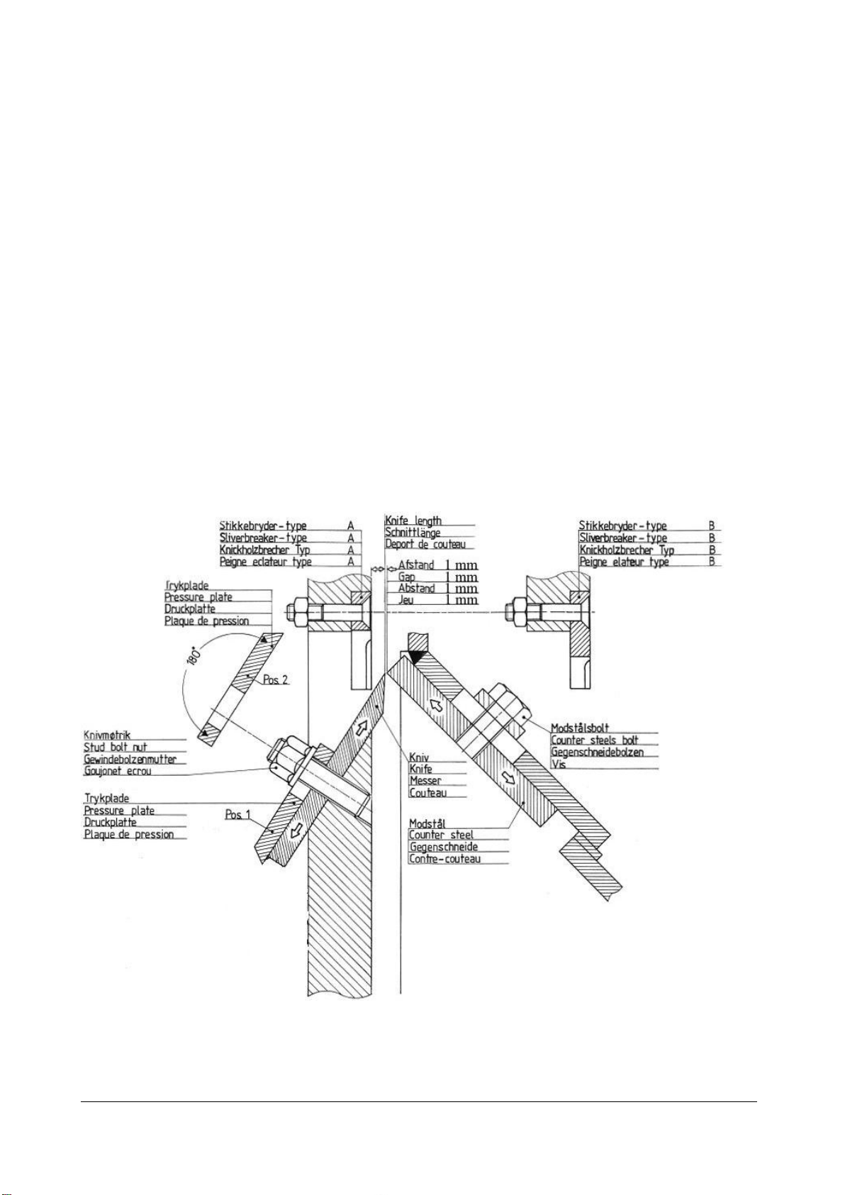
Remove the three bolts holding the horizontal anvil in place. You access these from outside and
below. Take the anvil out from above and turn/replace. Before replacing the anvil, both the anvil
and contact surface must be carefully cleaned. The gap between the knife edge and anvil must be
1 mm. (See Figure 12).
Figure 12 Gap between anvil and knife

Linddana A/S . Ølholm Bygade 70 . DK-7160 Tørring . T +45 75 80 52 00 . tp@linddana.com . www.linddana.com
Brugsanvisning: TP 230 fra dato 02.11.2015 ©Copyright 2008
16
The tightening torque for the anvil bolts must be 200 Nm/20 KPm. Use the wrench included in the
tool kit (can be purchased as extra equipment).
Unscrew the vertical anvil and remove from inside. Before inserting a new one, clean the contact
surface and the anvil carefully. Set the anvil at 1 mm from the knives. Use a feeler gauge. Tighten
the bolts for the vertical anvil to 200 Nm/20 KPm.
Once the anvils have been turned or replaced and all bolts tightened, draw the revolving feed
roller back into place. Refit the springs using multigrip pliers (See Figure 11).
Turn the rotor several revolutions to ensure there are no objects in the rotor housing. Close the
rotor housing and replace the bolts (See Figure 13).
Figure 13 Fitting bolts in the rotor housing

Linddana A/S . Ølholm Bygade 70 . DK-7160 Tørring . T +45 75 80 52 00 . tp@linddana.com . www.linddana.com
Brugsanvisning: TP 230 fra dato 02.11.2015 ©Copyright 2008
17
8.3.2 Knives
The machine is equipped with three knives.
The knives must always be replaced as a set. The knives form a set and should be sharpened so
that they are always of equal width. If the knives are not the same width, the rotor will not be
balanced, which will cause unnecessary strain on the bearings and vibrations throughout the
machine.
What to do:
Stop the machine and turn off any power. Loosen the bolts holding the two sections of the rotor
housing together and open the rotor housing.
Turn the rotor until the rotor lock connects with one of the ejector blades on the rotor. The rotor
is now locked (see Figure 14). Keep your fingers well away from the knives when turning the rotor.
Figure 14 Locking the rotor using the rotor
lock Figure 15 Knife measure
Remove the four nuts holding the knife and the clamping plate to the rotor. Remove the knife
and any sliver breaker. The contact surfaces on the cutting disc and the knife and sliver breaker
must be cleaned thoroughly before fitting knives and sliver breaker. When fitting, the nuts must
be lightly oiled (m=0.125), i.e. light oil, WD 40 or equivalent. Copper grease, MoS2or equivalent
low-friction grease must not be used.
When fitting knifes the knife measure (See Figure 15) is used for correct knife distance.
Check that the gap between knife edge and anvil is correctly set to 1 mm.
The nuts must be tightened to 200 Nm/20 KPm. Use the wrench, included in the tool kit, for this.
This can be purchased as extra equipment.
Once the knives have been replaced, turn the rotor several revolutions to ensure there are no
objects in the rotor housing. Close the rotor housing and tighten the bolts (See Figure 12).
Linddana A/S . Ølholm Bygade 70 . DK-7160 Tørring . T +45 75 80 52 00 . tp@linddana.com . www.linddana.com
Brugsanvisning: TP 230 fra dato 02.11.2015 ©Copyright 2008
19
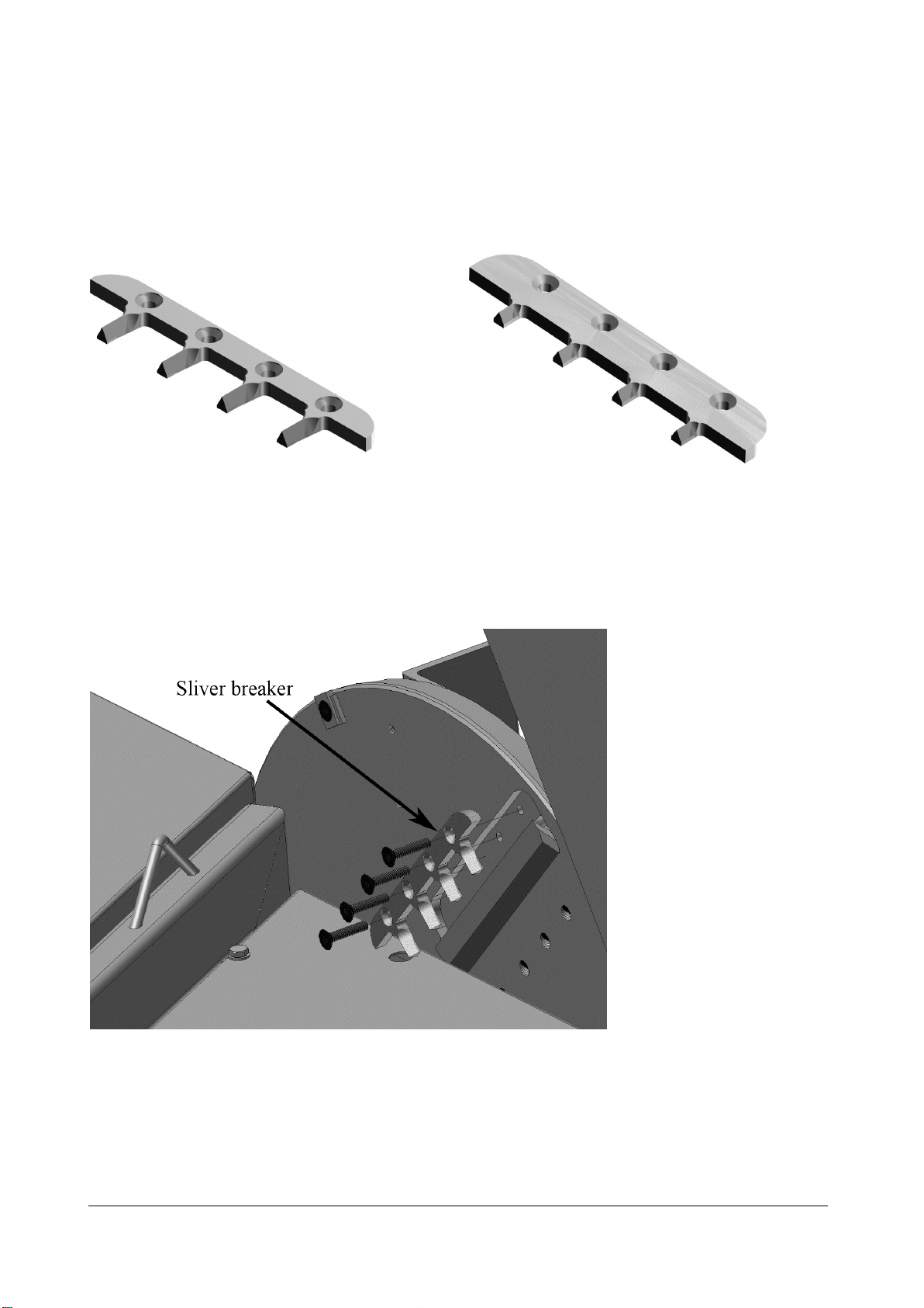
8.3.3 Sliver breakers
To improve the chip quality, the machine is equipped with type A sliver breakers at the factory
(see Figure 16).
When chipping hard seasoned wood, use type B sliver breaker (see Figure 17).
Type B sliver breaker is extra equipment.
Figure 16 Sliver breaker type A Figure 17 Sliver breaker type B
What to do:
Stop the machine and turn off any power. Loosen the bolts holding the two sections of the rotor
housing together and open the rotor housing. Remove the four bolts and nuts holding the sliver
breaker in place (see Figure 18).
Figure 18 Replacing sliver breaker
When using sliver breaker type B, the knife gap must be max. 8 mm.
Once the sliver breakers have been removed or replaced, turn the rotor several revolutions to
ensure that it runs freely and there are no loose objects in the rotor housing. Now close the rotor
housing and tighten the bolts (see Figure 13).
Linddana A/S . Ølholm Bygade 70 . DK-7160 Tørring . T +45 75 80 52 00 . tp@linddana.com . www.linddana.com
Brugsanvisning: TP 230 fra dato 02.11.2015 ©Copyright 2008
20
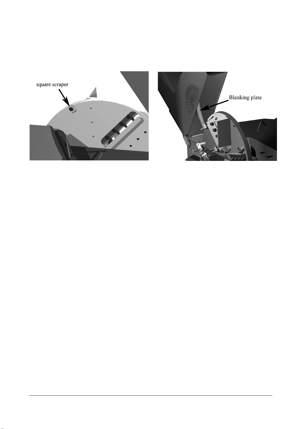
8.3.4 Scrapers and blanking plate
The machine is equipped with three square scrapers on the rotor disc, one triangular scraper in
the rotor housing and a blanking plate in the ejector tube (see Figure 19):
Figure 19 Location of scrapers and blanking plate
The purpose of the scrapers is to remove material that may jam the knives.
At the same time the square scraper on the rotor removes material that falls off before the
cutting disc.
This reduces the wear on the casing and reduces the fuel consumption.
The square scrapers can be turned once before they must be replaced, while the triangular
scraper and blanking plate must always be replaced once they become worn.
What to do:
Turn the rotor until the rotor locking bolt connects with one of the ejector blades on the rotor.
The rotor is now locked (see Figure 14).
Remove the countersunk bolts holding the square scraper in place on the rotor. Turn the square
so that a sharp corner points upwards. Clean the block and contact surface. Replace the square
scraper. If it is worn on two corners, the square scraper must be replaced. Always replace the
square scrapers on the rotor as a set. Replace the triangular scraper once it becomes worn.
The blanking plate is installed in the top section of the rotor housing and can easily be replaced by
removing three bolts on the outside of the rotor housing. If chip quality is not of crucial
significance, it can be beneficial to remove the blanking plate in the ejector tube. This will increase
the capacity of the machine and save fuel. The blanking plate must be removed when chipping
wet softwood with numerous needles. This ensures good discharge.
Once the scrapers have been turned or replaced, turn the rotor several revolutions to ensure that
it runs freely and there are no loose objects in the rotor housing. Now close the rotor housing and
tighten the bolts (See Figure 13).
Linddana A/S . Ølholm Bygade 70 . DK-7160 Tørring . T +45 75 80 52 00 . tp@linddana.com . www.linddana.com
Brugsanvisning: TP 230 fra dato 02.11.2015 ©Copyright 2008
21
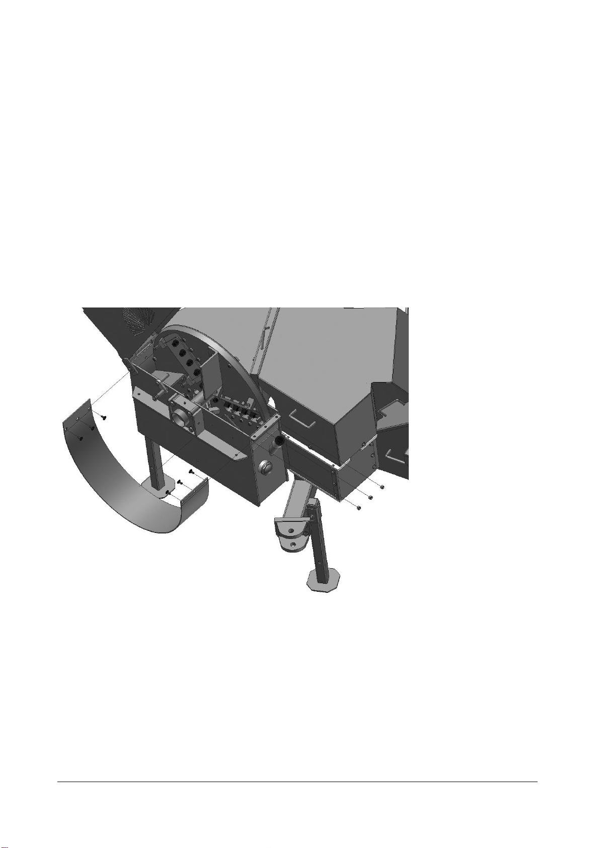
8.3.5 Casing
The TP 230 is equipped with a replaceable casing at the base of the rotor housing. The casing
bears the wear and tear that would otherwise affect the base of the rotor housing.
What to do:
Stop the machine and turn off any power. Loosen the bolts holding the two sections of the rotor
housing together and open the rotor housing. Remove the top section of the rotor housing.
Remove the six bolts and nuts securing the casing to the bottom section of the rotor housing
(Figure 20).
Tap the section of the casing protruding beyond the edge of the rotor housing on the hinge side
with a hammer to loosen it. The casing can now be drawn out.
Figure 20 Replacing the casing
Before a new casing can be fitted, any dirt and rust must be cleaned from the base of the wood
chipper. Fit the new casing using six bolts. Replace the top part of the rotor housing.
Once the casing has been replaced, turn the rotor several revolutions to ensure that it runs freely
and there are no loose objects in the rotor housing. Now close the rotor housing and tighten the
bolts (see Figure 13).
This manual suits for next models
3
Table of contents
Other Linddana Chipper manuals

Popular Chipper manuals by other brands

WoodMaxx
WoodMaxx WM Series manual

Farmi Forest Corporation
Farmi Forest Corporation VALBY CH 222 OPERATION, MAINTENANCE AND SPARE PARTS MANUAL

Mighty Mac
Mighty Mac TPH475 instructions

AL-KO
AL-KO Solo TCS Duotec 2500 manual

Timberwolf
Timberwolf TW 280TDHB instruction manual

Farmi
Farmi 381 HFC OPERATION, MAINTENANCE AND SPARE PARTS MANUAL


