Nortrac 296025 User manual
1
Owner’s Manual
Instructions for Installation/Set-up, Operation, Servicing, & Storage
Portable Outdoor Use-Only, Power Take-Off (PTO) Chipper
Make sure you completely read and understand this manual before using the chipper for the first time. If
you have any questions, contact your retail or rental dealer or NorTrac Customer Service at 1-800-521-
0438 WARNING
READ and UNDERSTAND this manual completely before using the chipper!Failure to properly set
up, operate, and maintain this chipper could result in serious injury or death to the operator or bystanders. In
addition, PTO shaft can become airborne and cause severe injury if improperly secured.
In particular, be aware of the following hazards:
Failure to properly mount and secure the chipper to the tractor may cause the unit to flip violently during
use, which could cause severe injury to the operator or bystanders, or damage to surrounding objects.
Never operate the chipper without proper PTO guarding, including a freely rotating shaft guard. Clothing or
hair can become rapidly entangled in unguarded rotating PTO shaft or connections, resulting in serious
injury or death.
Make sure PTO driveline shaft is securely locked at both ends. An unlocked PTO shaft can whip or become
dangerously airborne.
Keep hands and feet away from inlet and discharge openings.
Do not allow children under the age of 18 or untrained adults to operate.
Wear eye protection and other personal protection against flying debris.
Do not attempt to perform adjustments, declog or clean unit while engine is running.
Make sure no children or bystanders are within 100’ (feet) of chipping operation.
Protect cars, windows and other objects within 100’ from flying debris.
Be aware of potential for carbon monoxide (CO) poisoning.
Avoid using in slippery, muddy, wet or icy conditions where falls may occur.
These and other hazards in the manual and summarized at the end under “Important Safety
Information.”
STOP!
ASSEMBLY REQUIRED: This product requires assembly before use. Some of the components in this unit
are heavy and cannot be lifted by one person safely. Please plan on assembling this product when another person
can be available to help out. See “Assembly Instructions” section for instructions.
INSPECT COMPONENTS: Closely inspect to make sure no components are missing or damaged.
See the “Receiving and Transporting” section for instructions on whom to contact to report missing or
damaged parts. Any Questions, Comments, Problems, or Parts Orders
Call your dealer or NorTrac Customer Service 1-800-521-0438
MODEL NUMBER: 296025
SERIAL NUMBER: _____________
M296025D
Hazard Signal Word Definitions
2

Table of Contents
3
Part I. Introduction
About Your Chipper............................................................................................................................4
Safety Labels Locations......................................................................................................................5
Receiving & Transporting:
Initial Inspection ..........................................................................................................................7
Assembly Instructions..................................................................................................................8
Connecting To Your Tractor........................................................................................................9
Moving Instructions.....................................................................................................................12
Part II. Operation
Operation:
1. Pre-start Check List & Procedures...........................................................................................13
2. Starting/Stopping .....................................................................................................................14
3. Feeding Material/Clearing Jam................................................................................................15
4. Storing the Chipper..................................................................................................................16
Part III. Maintenance and Repair
Maintenance (To be done by owner or Rental Dealer).......................................................................17
1. Chipping Knife........................................................................................................................19
2. Belt and Sheave Care ..............................................................................................................22
3. Maintenance Schedule.............................................................................................................25
4. Bolt Torque Chart....................................................................................................................26
Specifications.........................................................................................................................................27
Machine Component Identification..............................................................................................28
Parts Explosion ....................................................................................................................................30
Part IV: Summary of Important Safety Information
Summary of Important Safety Information.........................................................................................33
Limited Warranty Policy..................................................................................................................36

About Your Chipper
4
Owner/Operator/Renter Training
Read and follow all instructions and safety precautions presented throughout this manual. A summary
of important safety information can be found at the end of the manual. Keep this manual for reference
and review. If the owner of this unit is different than the operator, give a copy of this manual to any
operator. Keep in mind that the operator or user is responsible for accidents or hazards occurring to
other people, their property, and themselves.
Rental Companies
Check the storage tube on the cutter guard side (beneath hopper) to make sure the chipper manual is
inside. All persons to whom you rent/loan this chipper must have access to this manual. Advise all
persons who will operate the machine to read it. You should also provide personal instruction on how
to safely operate the chipper and remain available to answer any questions a renter/borrower might
have. If videos are available, have renter watch training video.
Product Suitability
Your chipper is designed to only chip wood. A chipper knife is mounted on a revolving flywheel and
converts branches fed into the chipper hopper into “chips”. Make sure you completely read and
understand this manual before using the chipper for the first time.
Before using, the user shall determine the suitability of this product for the job it will be used for. The
user assumes liability for any non-intended or misuse of the product.
As is common with all manufacturers, NorTrac is constantly improving its products. The specifications
outlined herein, while believed to be accurate at publication, are subject to change without prior notice
or obligation. Do not modify or alter this chipper. The purchaser and/or user shall assume the potential
liability for any modification and/or alterations of this equipment from its original design and
manufacture.
Contact your rental or retail dealer or NorTrac Customer Service at 1-800-521-0438 for any questions
about the appropriate use of this chipper or about optional accessories.
Warranty Registration
Please fill out and submit the warranty registration card so that we may contact you with updated
information regarding product literature, replacement parts, or safety information.

Safety Label Locations
5
The following safety labels appear on your chipper. These are warnings and instructions
particularly important for proper safety and functionality. Other warnings and instructions also
appear throughout this manual. Reading and understanding these labels below will expedite your
safe use of the product. The labels on the machine will then serve to further remind you of
important safety and operation procedures.
WARNING: Replace Missing Labels
ALWAYS make sure safety labels are in place and in good condition. If a safety label is missing
or not legible, order new labels.
To order
Replacement
Safety Labels,
call NorTrac
Customer Service at
1-800-521-0438

Safety Label Locations
6
Part #
Ref #
Description
Qty
796191
2
Infeed Hazard, Danger
2
3
General Precautions and Operation
2
796192
1
Flying Debris, Warning
2
4
Amputation Hazard, Discharge Chute
1
5
Belt Entanglement, Warning
1
6
Amputation Hazard, Guard
2
7
PTO Hazard, Danger
1
786689
8
Spiral
2
799952
9
Spark-Strike Warning
1
1
3
4
2
6
5
7
8
9

Receiving & Transporting
7
Initial Inspection
You should inspect the chipper immediately after taking possession and before use.
See the “Machine Component Identification” section of this manual for a diagram of the chipper and all
its components.
If you have missing components, contact your retail or rental company or NorTrac Customer Service at
1-800-521-0438.
Fastener Bag
Contents
5/16" NYLOC NUT
QTY: 28
PART# 82020
5/16" x 3/4"
CARRIAGE BOLT
QTY: 4
PART# 82088
5/16" x .625"
CARRAIGE BOLT
QTY: 18
PART# 82425
5/16" USS FLAT
WASHER
QTY: 12
PART# 82021
5/16" x 1" BOLT
QTY: 6
PART# 82091

Receiving & Transporting
8
Hopper
hood
Cutter
housing
5/16"nyloc
nut
5/16" flat
washer
5/16" x
1" bolt
Assembly Instructions
1. Attach Shields
to Top Hopper
1. Using (4) 5/16" x 3/4" carriage
bolts and (4) 5/16" nyloc nuts,
assemble in order shown.
2. Torque to 11 ft./lbs.
3. Assemble
Hopper Sides
1. Attach hopper right side to
hopper bottom, using (5)
5/16" x 0.625" bolts and (5)
5/16" nyloc nuts making sure
the flange on the hopper
bottom is in the inside.
2. Repeat with hopper left side
to hopper bottom.
3. Install hopper top and shields
to left and right hopper sides
using (8) 5/16" x 0.625" bolts
and (8) 5/16" nyloc nuts.
Make sure hopper top flanges
are in the inside.
4. Torque to 11 ft./lbs.
5. Attach Hopper
to Chipper
Note: Two people are required –one to hold the hopper and one to fasten.
1. Assemble hopper to cutter housing using
(6) 5/16" x 1" bolts, (12) 5/16" flat
washers, and (6) 5/16" nyloc nuts.
Torque to 11 ft./lbs.
Clear vinyl shield
Plastic shield
Shield
backer plate
Hopper top
5/16"
nyloc
nut
5/16" x 3/4" carriage bolt
Right hopper side
Hopper left side
Hopper bottom
5/16" nyloc nut
5/16" x 0.625"
bolt
Hopper top & shields
Flanges
Hopper right side
Note: Carriage bolt
heads are inside the
hopper, nyloc nuts
are outside the
hopper.

Receiving & Transporting
9
Connecting to your Tractor
WARNING
The chipper must be correctly mounted and then attached to the tractor 3-point hitch for safe operation.
Follow the instructions below for safely mounting and connecting the chipper.
1. Read instructions
Review your tractor manual or check with your dealer for instructions
and safety information about how to properly connect the chipper to your
tractor’s 3-pt hitch and PTO shaft.
Ensuring a correct hook-up to your tractor is your responsibility.
2. Tractor turned off
& parking brake
engaged
Turn off the tractor and engage the parking brake before attaching the
chipper.
3. Attach to tractor
3-point hitch links
Attach chipper to tractor’s 3-point hitch links.
a. Connect the tractor’s lower link to the lower hitch studs of the chipper.
Secure with lynch pins.
b. Connect the tractor’s upper link to the upper hitch pin of the chipper.
Secure with lynch pin.
Upper hitch pin
Tractor's upper link
Lynch pin
Lynch pin
Tractor's lower links
Lynch pin
Lower hitch stud
Receiving & Transporting
10
WARNING
An improperly attached chipper could become dislodged during transportation
or operation, which could result in serious injury to the operator or bystanders.
Do not drive the tractor or operate the chipper until you are sure the chipper is
properly attached and hitch pins are fully engaged.
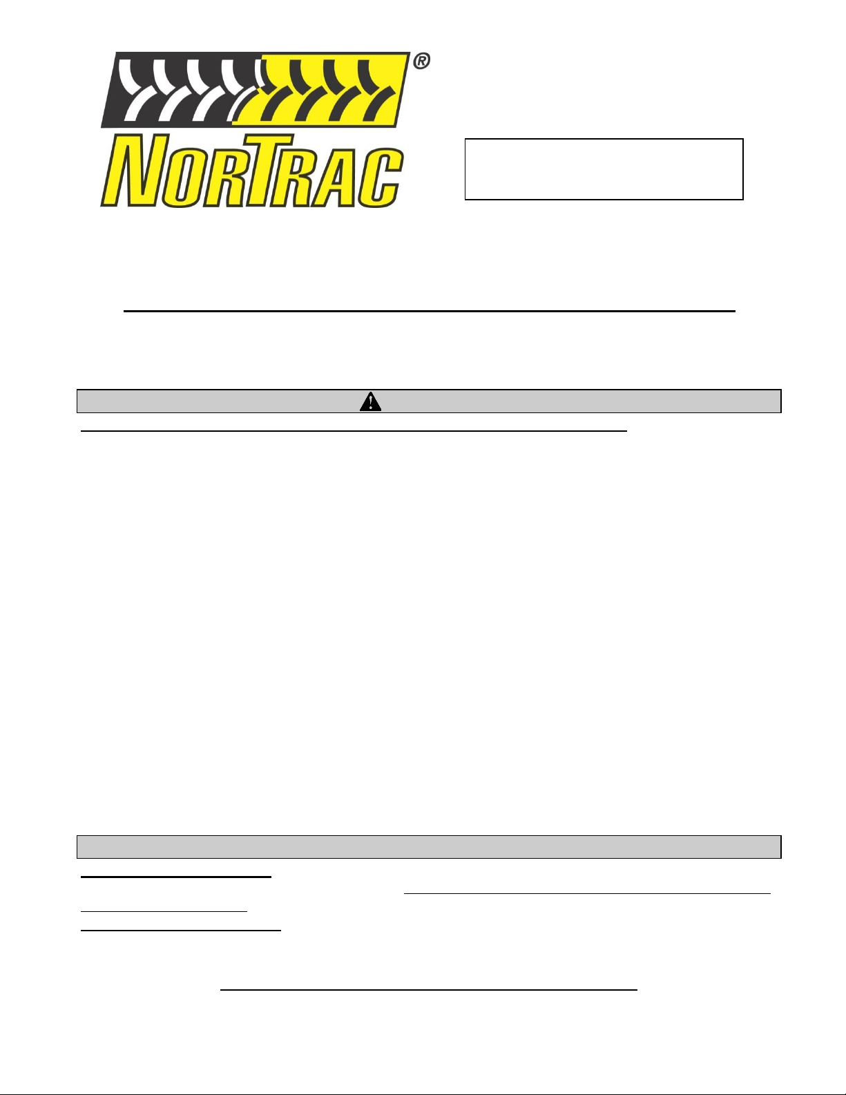
Attach PTO
driveline shaft
Connect the PTO driveline shaft to the tractor:
1. Align the tractor and chipper to minimize the driveline angle in both the
horizontal and vertical planes; it should be as near to a direct line in all
directions as possible. The angle should never exceed 25°in any direction.
Note: Proper alignment will increase the life of the power takeoff shaft,
reduce wear on the bearings of the PTO and chipper, and reduce
vibration.
2. Ensure that the tractor PTO is disengaged and the tractor is turned OFF.
3. One half of the PTO driveline is already attached to the chipper's input
shaft.
4. Slide the other half of the PTO driveline into the half connected to the
chipper.
5. Connect the other end to the tractor PTO stub. Pull back on collar and slide
coupler onto 6-tooth spline PTO stub. Push collar forward to lock onto
PTO stub. Pull on driveline to ensure proper connection.
Top View
Side View
Max. 25°
Max. 25°
Driveline
Set screws

Receiving & Transporting
11
WARNING
Make sure PTO driveline shaft is securely locked at both ends. Unlocked
PTO shafts can whip or become dangerously airborne.
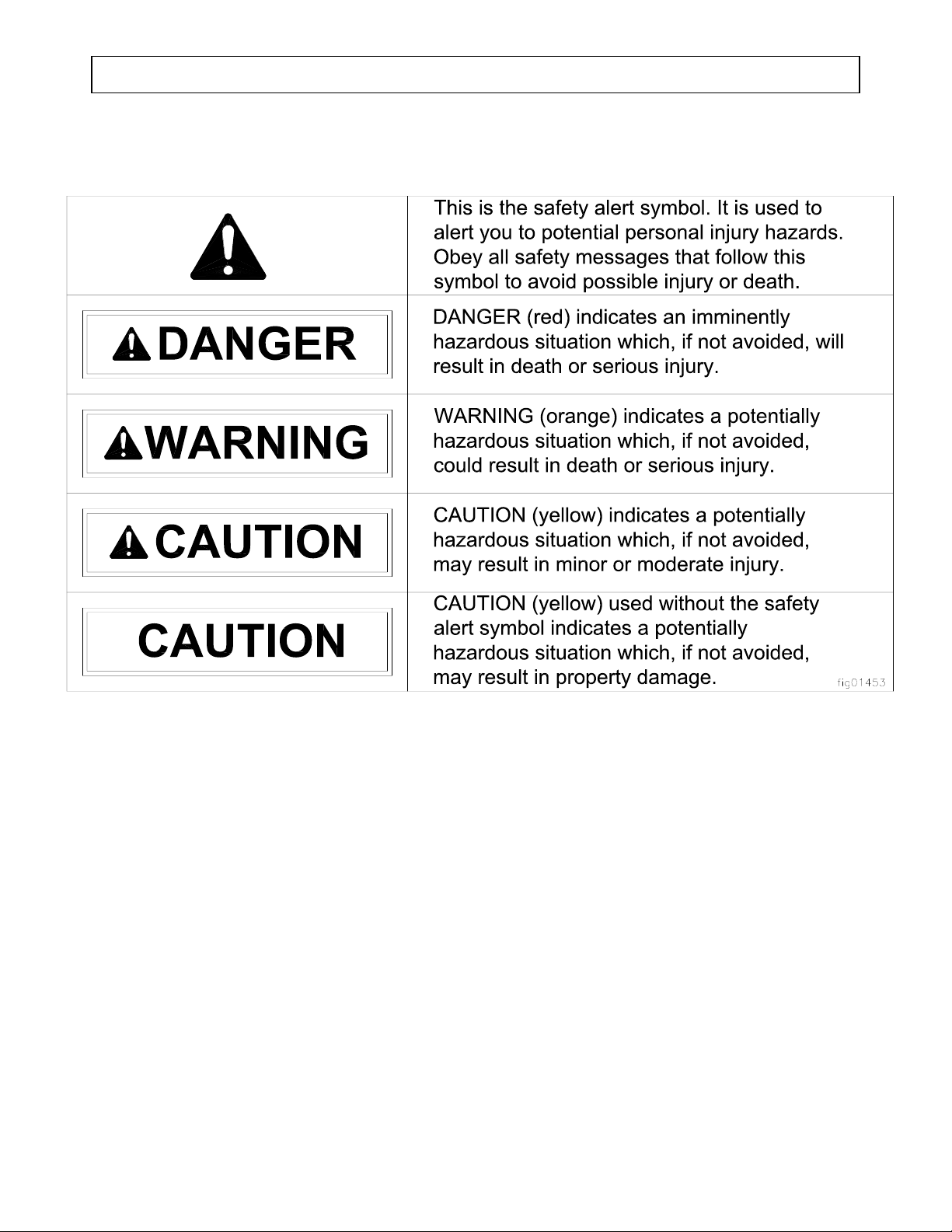
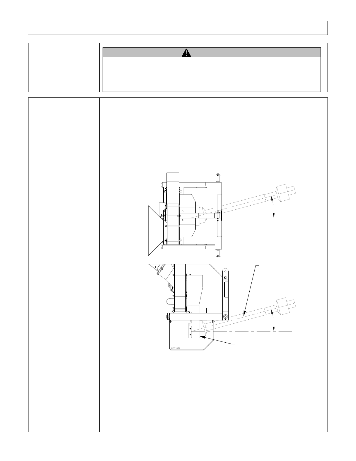
Secure driveline
guard, check shields
& attach safety
chains
1. A driveline GUARD must ALWAYS be used with the driveline shaft.
Secure the driveline guard according to manufacturer's instructions.
2. Make sure the tractor and chipper shields are in place at both ends of the
driveline shaft:
On the tractor where the driveline connects to the PTO stub.
On the chipper where the driveline connects to the input shaft.
3. Secure PTO safety chains to a stationary part of the chipper frame and
tractor to prevent guards from turning.
WARNING
Never operate the chipper without proper PTO guarding, including a freely
rotating shaft guard as well as tractor and chipper shields at both ends.
Clothing or hair can become rapidly entangled in unguarded rotating PTO
shaft or connections, resulting in serious injury or death.
Safety chains

Receiving & Transporting
12
Moving Instructions:
WARNING
Serious injury can occur if the tractor on which the chipper is mounted is driven unsafely.
1. Drive to desired
location
Drive tractor and chipper carefully to desired work site.
Important safety instructions:
Read tractor instructions. Review safety instructions in your tractor
manual with regard to driving with 3-point hitch mounted equipment
attached.
Securely attached. Be sure chipper is securely attached before transporting.
Make sure chipper is raised as to not contact the ground or objects on the
ground. Damage can occur if chipper is dragged on the ground
Added length. Be aware of the added length of the chipper.
Never operate the machine at high transport speeds on hard or slippery
surfaces.
Reduced road stability. Be aware that heavy, 3-point hitch mounted
equipment can reduce road stability, regardless of the amount of front-end
counterweight added. Drivers should take extra caution when driving with
the chipper attached. Reduce your speed and take extra caution during turns
or while driving on rough or sloped terrain.
On public roads. If transporting the chipper on a public road, make sure to
comply with all local, state, and federal requirements.
Exercise extreme caution when operating on or crossing gravel drives,
walks or roads. Stay alert for hidden hazards or traffic.
No riding or cargo on chipper. Never ride or transport cargo on the
chipper.
Unattended. Turn off the tractor before leaving the chipper unattended.
Under the influence. Never transport or operate this chipper while under the
influence of alcohol, drugs, or medication.
2. Engage parking
brake
Make sure the tractor’s parking brake is engaged before operating the chipper.
WARNING
If the parking brake is not engaged, the tractor could roll while you are
operating the chipper. Personal injury could result. Always engage the parking
brake before leaving the tractor while the chipper is attached.

Operation
13
1. Pre-start Check List & Procedures
WARNING: High Energy Machine
This is a high-powered machine. It has moving parts operating with high energy and at high speeds.
Safe procedures must be used to avert serious injury or death. Unsafe operation will create serious
hazards for you, as well as anyone else in the nearby area.
Each time you get ready for a chipping session and before starting the engine you should follow these
items:
Wear Personal Protection
Establish Safe Working Area
Remove Hazardous Chipping Materials
Only Work During Daylight
Wear Personal
Protection
Use approved protective clothing and approved protective equipment when
using the machine.
Wear ANSI-approved and OSHA-compliant safety glasses with side
shields and a hard hat.
Use of earplugs or another hearing protection device if working within
15-20 feet of the running chipper for longer than a few minutes. Hearing
can be damaged from prolonged close-range exposure to the type of
noise produced by this chipper.
Wear long pants to protect legs from flying debris.
Wear gloves with no cuffs.
Never wear jewelry or loose-fitting clothing when starting or operating
the chipper or any mechanical device. Loose or dangling apparel,
jewelry or hair can become entangled in moving parts.
Establish Safe
Working Area
Layout a safe working area that best fits your project and/or situation by:
Using safety tools such as
barricade signs, safety cones and
caution tape.
Determining placement of
equipment and brush pile (i.e. on
or off the street) that will
minimize interference with auto
traffic.
Keeping children, pets and
onlookers at a safe distance.

Operation
14
Remove Hazardous
Chipping Materials
Thoroughly inspect the area where you will be working and remove all
foreign objects.
Look for rope, wire, etc. and remove these objects before chipping.
(Inserting these objects into the chipper could damage the machine and/or
cause injury)
Work During
Daylight Hours
Use the machine only in daylight or in well-lit conditions. Never operate the
chipper after dark.
2. Starting the Chipper
For detailed engine operation and maintenance information, always refer to the specific
tractor’s Owner’s Manual.
1. Engage parking
brake
Secure chipper from unintended movement—make sure the tractor’s
parking brake is engaged before operating the chipper.
WARNING: If the parking brake is not engaged, the tractor could roll
while you are operating the chipper. Personal injury could result.
2. Lower chipper
to level ground
The driveline angle should never exceed 25°.
Warm-Up Checks
Slowly bring the PTO speed up.
Listen for any unusual metal to metal sounds as chipper wheel is rotating.
Listen for any belt squealing indicating belt needs to be tightened or
replaced
(Unusual sounds may mean a need for repair or cleaning out foreign
material stuck in chipper. STOP engine and refer to “Maintenance and
Repairs” section of this manual)
If you don’t hear any unusual sounds, slowly bring PTO speed up to 540
rpm.
Normal Operation
Always operate the PTO at 540 rpm. Proper chipping requires 540
revolutions per minute.
3. Stopping the Tractor
Move throttle slowly to decrease engine speed until RPM is at its minimum.
Turn off PTO.
Turn tractor OFF.
Chipper knife will continue to rotate for a short time.

Operation
15
4. Feeding Material/ Clearing Jam
Feeding Material
DANGER: Amputation Hazard
Never place your hands, feet or any part of your body in the chipper hopper, discharge opening, or near any
moving part while the machine is running. If a feeding problem should occur, shut the machine down and
see Maintenance and Repair” section to address the problem.
WARNING: Feed brush from the side of the chute
Never stand directly in front of hopper opening. This will reduce the risk of you being caught and
dragged into the machine.
WARNING: Flying Debris Hazard
Stones, chips, and debris can cause serious injury or property damage. Debris can fly 100 ft in any direction
out of the chute and bounce off objects and hit operator, bystanders or breakable objects.
Chipping
The chipper is designed to accept wood only.
Feed branches in butt end first to keep the chipper from getting jammed and to reduce the
kickback of material.
Let go of the material once placed in the hopper.
Use a push stick to help feed small pieces and brush through the chipper. Keep your distance
from the machine’s moving parts. Do not push material into the chute with your hands or feet,
pitch fork, etc. Lay shorter pieces on top of longer branches when feeding them through the
machine.
Do not force material into the chipper. If the machine does not chip well, the chipper knife may
need to be sharpened or replaced, or the belts may need to be replaced or tightened.
Overloading the chipper hopper will cause the rotor speed to decrease. If you hear the engine
RPM decreasing, stop feeding material into the hopper until the material already in the machine is
chipped and the engine has returned to full speed.
Never allow an accumulation of processed material to build up in the discharge area as this will
prevent proper discharge and can result in kickback from the chipper hopper.
After striking a foreign object, stop the tractor, wait for all moving parts to come to a complete
stop, and disconnect the driveline from the tractor's PTO shaft. Thoroughly inspect the machine
for any damage, repair the damage before restarting and operating the machine.
If the machine should start to vibrate abnormally, stop the tractor, wait for all moving parts to
come to a complete stop, disconnect the driveline from the tractor's PTO shaft, and check
immediately for the cause. Vibration is generally a warning sign for trouble.
Clearing Jam
WARNING: Shut Off Engine to Clear Jam
Before attempting to unclog debris or clear a jam:
1. Shut off engine.
2. Wait for all rotating parts to come to a complete stop.
3. Disconnect PTO shaft from tractor and wait 5 minutes before servicing.

Operation
16
7. Storing the Chipper
Storage Procedures
Clean the chipper.
Inspect for worn or damaged parts.
Choose a covered storage location.
Storage Procedures
Clean chipper
Clean any dirt, debris and other foreign matter from the machine, discharge
chute and hopper.
Inspect chipper
Inspect the machine for worn or damaged parts and tighten any nuts or
screws that may have become loose.
Choose a storage
location
Store the chipper in a location that is:
Clean and dry.
Away from extreme high or low temperatures.
Covered for extra protection
1. Remove belt guard,
discharge chute and belt
guard side access plate.
2. Wearing gloves and safety
glasses; use a piece of wood
to push/pull clogged
material up and out of the
cutter housing.
3. Reinstall belt guard,
discharge chute and belt
guard side access plate.
Torque fasteners according
to torque chart before
operating.
Discharge chute
Flywheel
housing
Belt guard side access
plate
Belt guard

Maintenance and Repair
17
WARNING
ALWAYS shut off the tractor, make sure flywheel comes to a complete stop, and disconnect the
drive shaft before cleaning, adjusting, or servicing the chipper. Make sure all guards and shields
are replaced before using.
Maintenance safety
rules
Read and follow these safety rules whenever you will be servicing the
chipper:
Turn off chipper. Always turn off chipper, wait for all parts to come to
a complete stop, and disconnect PTO shaft from tractor before opening.
Replace guards/shields. Make sure all guards and shields are replaced
after servicing the chipper.
Repair. Major service, including the installation or replacement of
parts, should be performed only by a qualified service technician.
Obtain factory approved parts from NORTRAC at 1-800-521-0438.
Replacement parts. If a part needs replacement, only use factory
approved repair parts. Replacement parts that do not meet specifications
may result in a safety hazard or poor operation of the chipper and will
void the warranty.
After servicing. Make sure all tools and wrenches have been removed.
Start tractor and run chipper at low RPM. Listen for any metal against
metal noise or squealing noises from belts. If you should hear any
foreign noise stop engine and solve problems. Re-start and slowly bring
PTO to 540 RPM and run for 10 minutes to assure that repair was
successful.
Checking and
adjusting belt
tension
Drive Belts: Check and adjust according to pages 22-24.
Lubrication
Your chipper was greased at the factory. The operator needs to lubricate the
chipper main bearings periodically. Bearings should be greased weekly or
every 10 hours of use.
There are two chipper main bearings (in the front and rear) and two drive
shaft bearings (on the front and underneath).
Maintenance and Repair
18
To access drive shaft bearings, remove drive shaft guard. See pg. 19 for belt
guard removal instructions.
Note: Do not over grease. Too much grease will damage bearing seals.
Use EP-2 lithium base grease for bearings.
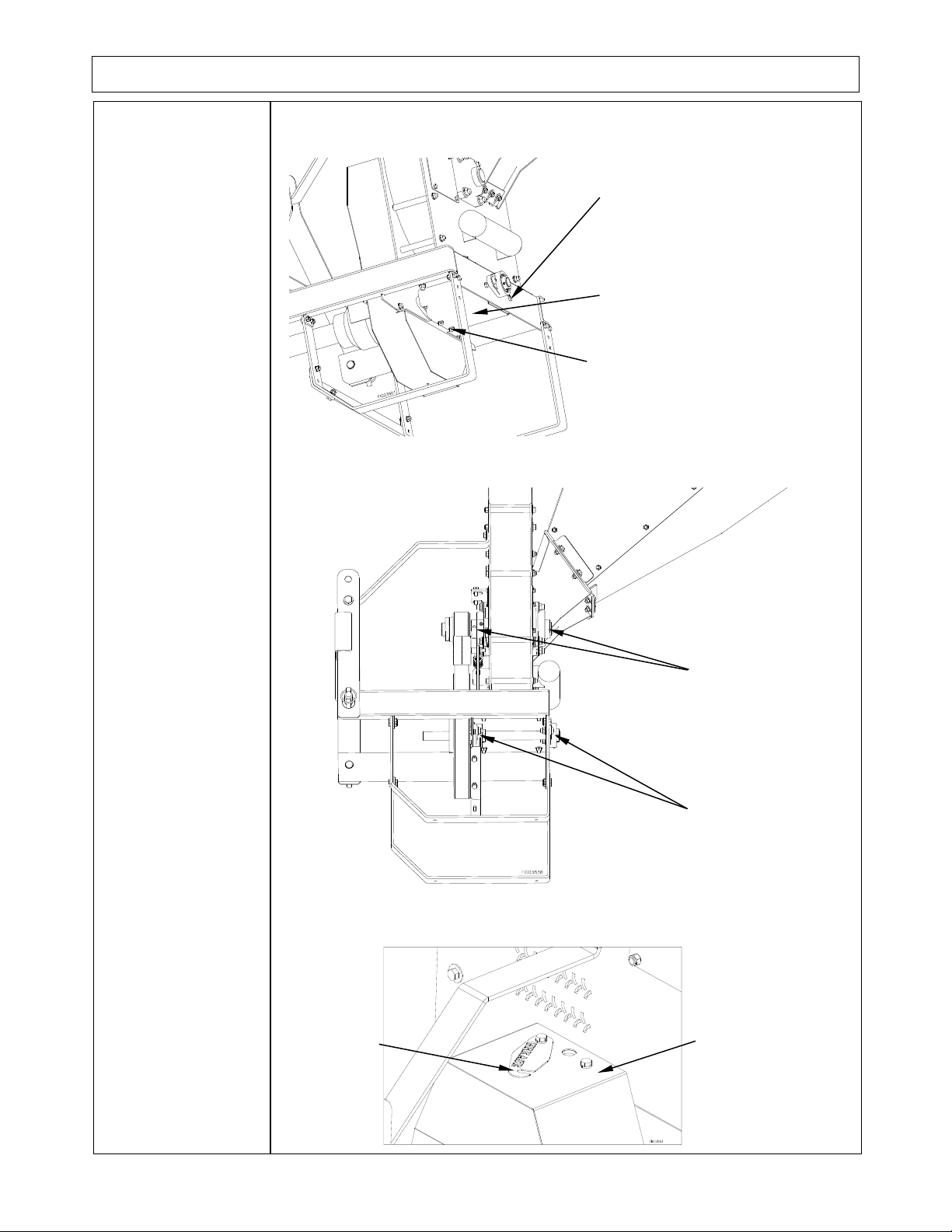
To access belt guard side main bearing's grease zerk, remove grease patch
plate attached to top of belt guard.
Main
bearings
Drive
bearings
Grease patch
plate
Belt guard
(2) 5/16"-18 x 3/4" bolt
(2) 5/16" flat washers
(2) 5/16" nyloc nuts
(2) 5/16"-18 x 1/2" bolt
(2) 5/16" split washers
Drive shaft guard

Maintenance and Repair
19
1. Chipping Knife
The blade (or knife) is called the flywheel blade. It is mounted on the large spinning wheel which
drives the blade (knife) past the incoming material at a high rate of speed and causes the “chipping”
action. Routine inspection of the chipper blade for sharpness will ensure the chipper is operating at
full efficiency. Operating with a worn or damaged knife or blade will cause extreme stress and
vibration to the machine and make chipping difficult for the operator.
While the chipper knife is made from the highest grade of chipper knife steel, which is heat treated
and ground to a very sharp edge, its life is relative to what is chipped. It may dull the first day or
last for months. The life span depends on the amount of dirt and rocks that enter the chipper.
Sometimes trees will have nails or wire embedded into the surface.
The knife should be checked for damage before each use. It should be turned or changed as
necessary.
A dull knife can:
Cause excessive fuel consumption.
Cause unnecessary stress and strain on the machine.
Produce poor quality chips.
Reduce production rate slowing the feed rate.
Actually wear further and faster.
To check, turn or change the chipper wheel knife you will have to remove the access plates.
Removing Belt Guard and Access Plates
Remove Belt
Guard
Remove (6) 5/16-18 x 3/4" bolts and (6) 5/16" split lock washers from the
top and toward the bottom of the belt guard.
Remove (4) 5/16-18 x 1/2" bolts and (4) 5/16" split lock washers from
underneath the frame.
5/16" x 3/4" bolts
5/16" split lock washers
5/16" x 1/2" bolts

Maintenance and Repair
20
Remove Access
Plates
Remove (8) 1/4"-20 x 1/2" screws and (8) 1/4" split lock washers.
Removing the Chipper Knife
Removing Knife
CAUTION
Wear gloves while changing the knife.
1. Clamp the flywheel to the wall of the cutter housing via the infeed side
access panel.
2. To remove knife, hold bolt heads stationary with 3/8” hex wrench and
loosen nuts with a ratchet and deep socket.
3. Clean knife and knife pocket on flywheel.
4. Sharpen, turn; or if it has nicks or damage, replace the knife.
5. Install all (4) knife bolts, washers and nuts before tightening. Hold bolt
heads stationary with 3/8” hex wrench and tighten nuts to 44 ft./lbs.
Infeed side access plate
1/4" x 1/2" screws
1/4" split lock washers
Belt guard side
access plate
Clamp
Cutter
housing
Flywheel
Table of contents


