LINDR CWP 100 GREEN Series User manual

WATER COOLERS
LINDR
Number 017-2020 REV00 Valid 2020-08-01
INSTRUCTION MANUAL
ENGLISH

2
IMPORTANT
This manual contains instructions for installation, use and operation of the
appliance. This manual is an integral part of the device. It must be stored in the
vicinity of the device for the entirety of its service life and must be made avai-
lable to the user any time the device is installed, moved, used or maintained.
Read this manual carefully before installing and using the device. It contains
important information necessary to ensure that all operations are done pro-
perly and safely.
WARNING:
Not following instructions may cause injury or
damage the device.
SYMBOLS AND MARKINGS USED IN THE MANUAL:
DANGER:
Risk of injury by electrical current.
NOTE:
This symbol indicates information and re-
commendations for the user.
WARNING:
The cooling system contains ammable coolant
R290 (propane)!
LINDR.CZ s.r.o.
Sadová 132
503 15 Nechanice, Czech Republic
mob.: + 420 775 715 494
tel. : +420 495 447 239
e-mail: info@lindr.cz
web: www.lindr.cz, www.lindr.eu
is manual is a translation of the original Czech manual.

WATER COOLERS
3
Contents:
1. Introduction
2. Description of the cooler
3. Machine plate
4. General instructions, measures and safety instructions
5. Installation and placement
6. Electrical connection
7. Testing
8. Warranty
9. Description of the device
10. Pouring uid into the tank
11. Beverage supply connection and pressurisation
12. Putting into operation
13. How to work with speed ttings
14. Tap installation
15. Temperature and adjustment
16. Cleaning the condenser
17. Keg coupler assembly
18. Keg tapping and untapping
19. Table of malfunctions
20. Spare parts
21. Sanitation by water
22. Maintenance
23. Inspection before every use
24. Periodic checks
25. Environmental protection
26. Technical data
..................................
..................................
..................................
..................................
..................................
..................................
..................................
..................................
..................................
..................................
..................................
..................................
..................................
..................................
..................................
..................................
..................................
..................................
..................................
..................................
..................................
..................................
..................................
..................................
..................................
..................................
4
4
4
4
5
7
7
7
7
9
10
13
14
14
15
15
16
17
20
21
21
22
22
22
22
23

4
1. INTRODUCTION:
Thank you for purchasing this LINDR product.
2. DESCRIPTION OF THE COOLER:
The under counter dispensing machine with
ice bank is primarily intended for cooling be-
verages in kegs. The water in these machines
serves to transfer cold to the beer line and also
as a cold accumulator.
This manual is intended for models:
CWP 100 GREEN LINE
CWP 200 GREEN LINE
CWP 300 GREEN LINE
CWP 200 mobile GREEN LINE
CWP 300 mobile GREEN LINE
CWP 300/k pro mobile GREEN LINE
AS-40 GREEN LINE
AS-80 GREEN LINE
AS-110 GREEN LINE
AS-110 INOX TROPICAL GREEN LINE
AS-160/200 GREEN LINE
AS-160 INOX TROPICAL GREEN LINE
AS-45 GREEN LINE
AS-110 INOX TROPICAL GREEN LINE
AS-160 INOX TROPICAL GREEN LINE
3. MACHINE PLATE:
4. GENERAL INSTRUCTIONS, MEASU-
RES AND SAFETY INSTRUCTIONS:
When using the device, follow basic safety
instructions stated by the manufacturer. The
cooling device is designed for ow-through
cooling of beverages. Any other use is consid
ered impermissible and therefore dangerous.
The supplier is not liable for damage caused
by incorrect use.
DO NOT USE THE DEVICE FOR PURPOSES
OTHER THAN THOSE STATED BY THE MANU-
FACTURER!
General safety principles. Observe the fo-
llowing safety instructions.
The supplier is not liable for damage caused
by activities carried out on this device without
observing the following instructions!
WARNING: Children aged 15 or more and
persons with reduced physical, sensory or
mental capabilities or insucient experien-
ce and knowledge may only use the device
when supervised or instructed in safe use of
the appliance and familiarised with potential
dangers.
WARNING: Children must not be allowed
to play with the appliance. Store all packaging
material out of reach of children (comes with a
plastic bag – suocation hazard).
WARNING: Cleaning and maintenance of
the appliance on the part of the user must not
be done by unsupervised children.
WARNING: Before connecting to main
electrical supply, check that the voltage and
frequency in the mains corresponds to the
data stated on the device.
WARNING: Always make sure that the soc-
ket you intend to plug the cooler into meets
the specications on the machine plate (volt-
age, frequency, input power).
WARNING: Before performing operations
on the device such as cleaning or maintenan-
ce, ALWAYS disconnect the device from power
supply: set the thermostat to „O“ position and
unplug the appliance from the socket.

WATER COOLERS
5
WARNING: Never place tools or other ob-
ject into the fan.
WARNING: Never touch electrical compo-
nents with wet or damp hands.
WARNING: To ensure the cooling unit
works properly and at full capacity, make sure
air supply to the unit is not obstructed.
WARNING: Water temperature during sa-
nitation must not be higher than 25 °C!
WARNING: Always make sure the power
socket you intend to plug the cooler into is ac-
cessible, so that the appliance can be imme-
diately unplugged in case of emergency.
WARNING: When unplugging the device
from the socket, grab the plug and pull it out.
Do not under any circumstances pull at the
cable; risk of damage.
WARNING: To turn the device o comple-
tely, unplug the appliance from the power soc-
ket.
WARNING: In the event the electrical wi-
ring of the product becomes damaged, sum-
mon a trained service technician. Do not under
any circumstances repair the device yourself.
WARNING: The cooling system contains
ammable coolant R290 (propane)!
WARNING: Emergency maintenance and
repair of the cooling system must be done by
trained, authorised technicians familiar with
cooling and electrical systems. The technicians
should have special training and qualication
for handling ammable substances in order to
perform service on coolers containing R290.
Follow basic regulations and safety measures
regarding service and repair!
WARNING: Do not use open ame or po-
tential sources of sparks in the vicinity of a
cooler using R290 coolant!
WARNING: After unpacking, place the coo-
ler so that heat created by the cooling unit can
be vented suciently.
WARNING: Do not place objects that could
prevent air circulation on top of the cooler.
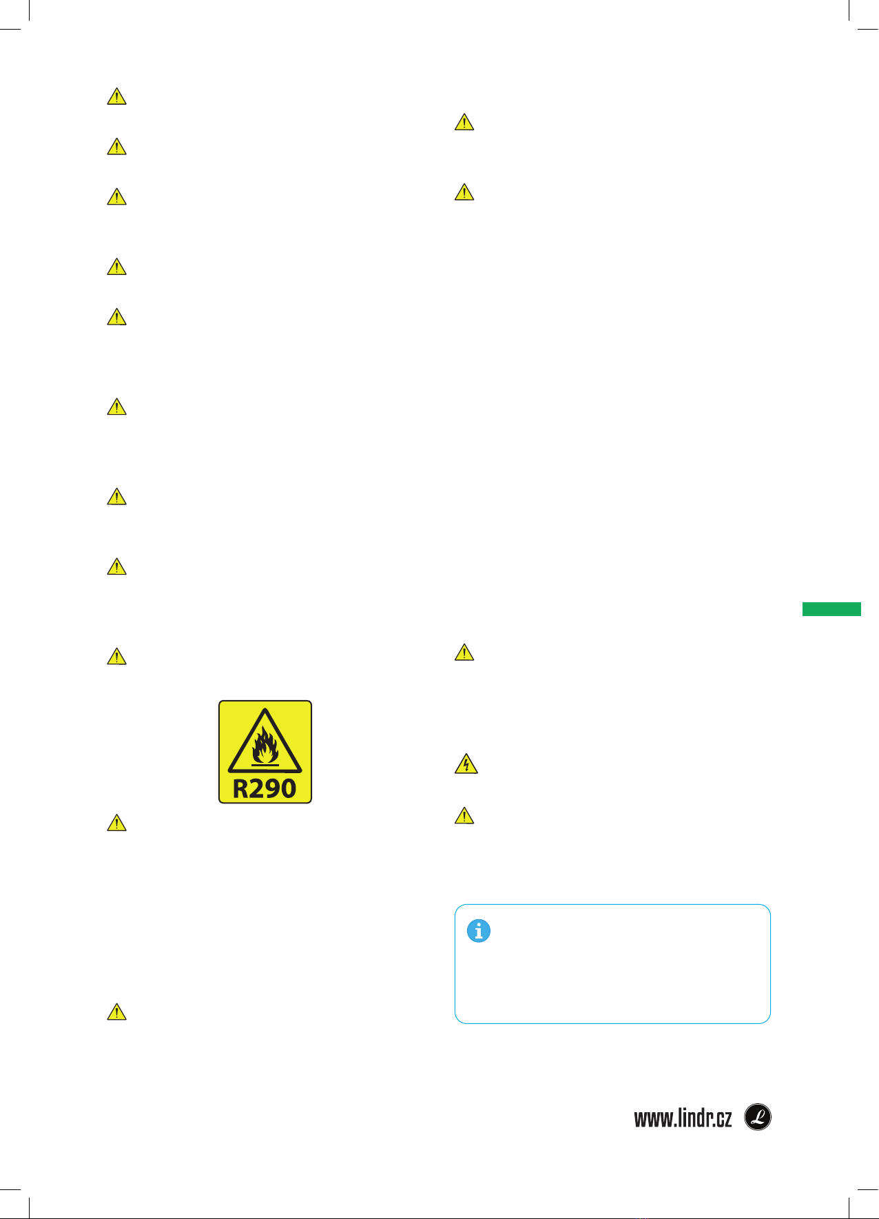
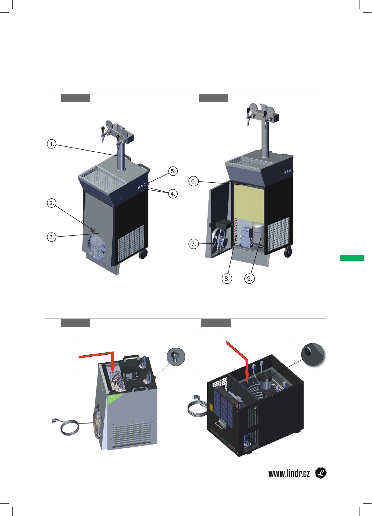
5. INSTALLATION AND PLACEMENT:
Place the cooler onto a stable, level surface
(maximum permitted inclination: 2 degrees).
The appliance requires unobstructed air circu-
lation.
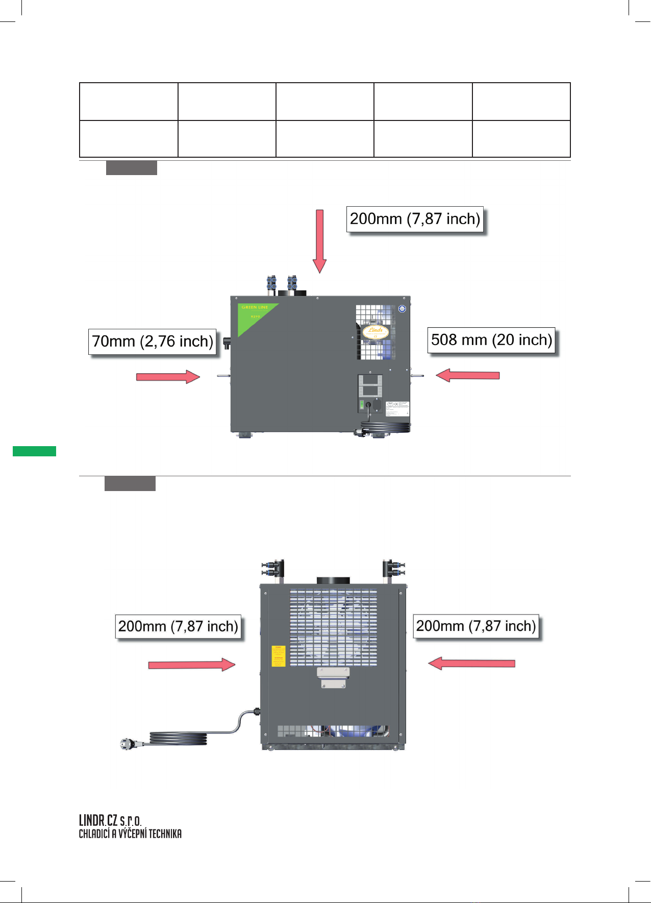
• Ensure sucient free space for air circulation
and heat dissipation.
• Ensure sucient supply of fresh air.
• The device must not be placed in an enclo-
sed space.
• The device must not be placed in the vicinity
of heat sources or exposed to direct sunlight.
Minimum distance of vents from an obstacle
that would limit air circulation must be in ac-
cordance with the table on page 6. Ideally, use
the device in a cool and well ventilated room.
The device is designed for use at ambient tem-
perature of at least 16 °C and at most 32°C.
WARNING: The device MUST NOT be used
or stored at ambient temperature lower than
0 °C. The device is designed for use in a normal
environment, always under a roof, protected
from rain or sunlight. Climate class N.
DANGER: Protect the cooler and electri-
cal connection from rain and spraying water!
WARNING: Do not under any circumstan-
ces lay the cooler on its side, not even during
transport.
NOTE: In order for the device to work
correctly and at maximum output, it is im-
portant to not cover up any of the device‘s
vents and ensure sucient air circulation.

6
obrázek 6 B
obrázek 6 A
Top Rear Right Side Left Side Front
200
(7,87)
200
(7,87)
200
(7,87)
508
(20)
200
(7,87)
Clerances, mm (inch)

WATER COOLERS
7
6. ELECTRICAL CONNECTION:
Connect the device to a power socket in ac-
cordance with specications on the machine
plate of the device. Electrical wiring is subject
to local regulations. If the power leads (cables)
are damaged, they must be replaced by the
manufacturer, their service technician or a si-
milarly qualied person to prevent risk of ha-
zardous situations.
DANGER: Do not use or turn on the device
if the power lead (cable) is damaged!
7. TESTING:
The product is delivered ready for immediate
use.
8. WARRANTY:
The device comes with a warranty in accor-
dance with general legal regulations of the
Czech Republic or in accordance with the tra-
de agreement. During the validity period of
the warranty, we will remove any defects on
the product free of charge, provided these de-
fects were not caused by excess wear, impro-
per handling, incorrect storage or by using the
product in a way that is counter to the instructi-
on manual or the product‘s design as dened
by the manufacturer. Materials replaced du-
ring the validity period of the warranty are our
property. The legitimacy of the warranty claim
is always decided by an authorised service
centre. Warranty provided by a retailer outsi-
de of the territory of the Czech Republic is go-
verned by the agreement between the retai-
ler and the buyer in their mutual relationship;
this agreement is not directly linked to the
manufacturer. The agreement does not give
the buyer the right to submit warranty claims
to the manufacturer. Transport expenses or
other costs are not covered by the warranty.
ATTENTION:
Electrical devices and appliances must be
checked/inspected at a time stipulated by
valid legislation of the country the device is
operated in. Inspection of wiring may only
be done by a person with valid authorisati-
on for this activity. Service work, provision
of spare parts and inspection is done by
the manufacturer or an authorised service
centre.
9. DESCRIPTION OF THE DEVICE :
9.1 Model series CWP 100, 200, 300:
gure 7 A gure 7 B
1. Overow
2. Inlet of the beverage
3. Recirculation pump
4. Outlet of the cooled beverage
5. Plastic tank
6. Fan
7. Cooling coil
8. Condenser
9. Motor compressor
10. Thermostat
11. Main switch
12. Power cable

8
9.2 Model series AS 80, 110, 160, 200:
gure 8 A
9.3 Model series AS 45 2 x Tap, AS 110 INOX TROPICAL 3 x Tap, AS 160 INOX
TROPICAL 4 X Tap :
1. CO2 inlet
2. Inlet of the beverage
3. Overow
4. Drip tray
5. Thermostat
6. Main switch
7. Tap
gure 8 B gure 8 C
1. Overow
2. Inlet of the beverage
3. Recirculation pump
4. Outlet of the cooled beverage
5. Plastic tank
6. Fan
7. Cooling coil
8. Condenser
9. Motor compressor
10. Thermostat
11. Main switch
12. Power cable

WATER COOLERS
9
9.4 Model series CWP 200 mobile, CWP 300 mobile, CWP 300/K pro mobile:
1. Dispense tower
2. Thermostat
3. Main switch
4. Inlet of the beverage
5. CO2 inlet
6. Plastic tank
7. Fan
8. Condenser
9. Motor compressor
gure 9 A gure 9 B
10. POURING FLUID INTO THE TANK:
Fill the plastic tank with clean water without any chemical treatment right up the overow.
gure 9 C gure 9 D
Pour the liquid here
Overow Overow

10
11. BEVERAGE SUPPLY CONNECTION AND PRESSURISATION:
gure 10 A
11.1 Connection and Pressurisation AS - 40 (coil 2x), C02/ N2
1. Beverage inlet
2. Beverage outlet
3. Keg coupler (A-system, S-system, M-sys-
tem)
4. F 5/8 x 9.5 mm speed tting
5. F 5/8 x 8 mm speed tting
6. Y 8 x 8 x 8 mm speed tting
7. CO2 pressure reducing valve
8. Beverage
9. JG SS 9.5 x 8 mm speed tting
10. JG 12.7 x 8 mm speed tting
11. JG F7/16 x 8 mm speed tting
12. Python
WARNING: After connecting the cooling coil the water level may drop in the plastic tank,
so check again and add water if necessary.
WARNING: Before starting, ll the tank with clean water up to the overow. Do not use
any chemicals, as this could damage the cooling system. An ecological antifreeze mixture
based on propylene glycol can be used for cooling to temperatures below freezing.
WARNING: Check the connection of the pump outlet, if it is not connected, water will
spray from the pump outlet after switching on the device.

WATER COOLERS
11
gure 11 A
11.2 Connection and Pressurisation AS - 80 (coil 2x), C02/ N2
1. Beverage inlet
2. Beverage outlet
3. Plug for agitator pump
4. Keg coupler (A-system, S-system, M-sys-
tem)
5. F 5/8 x 9.5 mm speed tting
6. F 5/8 x 8 mm speed tting
7. Y 8 x 8 x 8 mm speed tting
8. CO2 pressure reducing valve
9. Beverage
10. JG SS 9.5 x 8 mm (2x) speed tting
11. JG 12.7 x 8 mm (2x) speed tting
12. Python
13. JG F7/16 x 8 mm speed tting
RECOMMENDATION: Only use quick couplings to connect beverage hoses. For
the connection of tubes for the beverage use only ttings and clips specied by
the supplier. Use a calibrated hoses.

12
gure 12 a
11.3 Connection and Pressurisation CWP-200 (coil 4x), C02/ N2
1. Beverage inlet
2. Beverage outlet
3. Thermostat
4. Keg coupler (A-system, S-system, M-sys-
tem)
5. F 5/8 x 9.5 mm speed tting
6. F 5/8 x 8 mm speed tting
7. Y 8 x 8 x 8 mm speed tting
8. CO2 pressure reducing valve
9. Beverage
10. JG SS 9.5 x 8 mm (4x) speed tting
11. JG 12.7 x 8 mm (2x) speed tting
12. Python
13. JG F7/16 x 8 mm speed tting

WATER COOLERS
13
WARNING: Check that all joints are suciently leak-tight after connection.
12. PUTTING INTO OPERATION:
1. Connect the air line and the beer line.
2. Connect the recirculation coil to the dispense tower.
3. Pour the liquid into the plastic tank.
4. Connect the cooler to the mains.
5. Switch to turn on the cooler.
6. Set the desired temperature on the thermostat - see point 15.
7. Tap the keg, see point 18, tapping the keg.
8. Cooling beverage is now underway. After being cooled, you can dispense the beverage.
ATTENTION: For AS models where a stirrer pump is installed, be sure to connect the pump
cable to the socket on the cooler. The pump with stirrer ensures an even temperature in the
entire water bath and cools the beverage up to the tap.
gure 13 A
WARNING: If a leakage is found, untap the keg according to point 18 and turn o the
device. Fix any leaks found on the tubing. If a leak is found inside the device or you are unsure
how to proceed, contact a service centre.

14
14. TAP INSTALLATION:
gure 14 C
gure 14 D
1.
Turn the compensator lever (1.), so that it points down (see gure).
The compensator lever on the tap is used to adjust the ow rate.
2.
Fit the tap perpendicularly onto the spline.
3.
Secure with a are nut and turn left. (loosen to the right).
4.
Tighten with the enclosed wrench.
gure 14 E
gure 14 F
min.
max. 1.
13. HOW TO WORK WITH SPEED FITTINGS:
13.1 Speed Fitting Installation:
Grasp the speed tting and insert the hose all
the way inside the speed tting body (ca. 20
mm). The end of the hose must be straight so
that it plugs fully into the coupling. If the hose
will not go in, moisten the end of the hose.
gure 14 A
13.2 Speed Fitting Removal:
Hold the grey ring tight against the body of
the speed tting and pull out the hose.
gure 14 B
WARNING: If you do not hold the grey ring but pull at the hose, the speed tting will cut
even deeper into the hose.
WARNING: Hoses must not be pressurised during removal.

WATER COOLERS
15
16. CLEANING THE CONDENSER:
gure 15 D gure 15 E
gure 15 F gure 15 G
1. Remove the four screws holding the lid.
2. Remove the lid.
3. Remove the fan.
4. Clean the condenser with compressed air.
gure 15 A gure 15 B gure 15 C
15. TEMPERATURE AND ADJUSTMENT:
The temperature of the cooled beverage is controlled by a mechanical thermostat in
temperature range of 2 °C to 8 °C. The thermostat has a numerical scale of 1-7.
0 = OFF 1 =
MAX. BEVERAGE TEMPERATURE (8°C)
7 =
MIN. BEVERAGE TEMPERATURE(2°C)

16
CHECK VALVE
gure 16 A gure 16 b
gure 16 c gure 16 d
WARNING: Before you screw the speed tting onto the 5/8“ thread, make sure the keg
coupler (air inlet for delivery medium) has a lip valve (check valve) tted on it.
17. KEG COUPLER ASSEMBLY:
17.1 Outlet for Keg Pressurisation:
Variant of connection with the use of a bushing; the hose is tted onto the bushing and axed
with a clip.
gure 16 E

WATER COOLERS
17
gure 17 A gure 17 b
18. KEG TAPPING AND UNTAPPING:
18.1 Keg Tapping:
Procedure for tapping a keg using an S-system keg coupler:
WARNING: Make
sure the adapter is clean
before tapping the keg!
S-system keg coupler
17.2 Outlet for Beverage:
Screw an F 5/8“ x 3/8“ (9,5 mm) speed tting onto the keg coupler.
5/8“-3/8“(9,5mm)
5/8“ - 5/16“ (8mm)

18
18.2 Keg Untapping:
Procedure for untapping a keg using an S-system keg coupler:
gure 18 D gure 18 E
gure 18 F
gure 18 A gure 18 B
gure 18 C

WATER COOLERS
19
18.4 Keg Untapping:
Procedure for untapping a keg using an A-system keg coupler:
gure 19 E gure 19 F
gure 19 C gure 19 D
18.3 Keg Tapping:
Procedure for tapping a keg using an A-system keg coupler:
A-system keg coupler
gure 19 A gure 19 B
WARNING: Make sure the
adapter is clean before tapping
the keg!

20
NOTE: If the defect persists even after the above steps are taken, contact a service centre.
19. TABLE OF MALFUNCTIONS
Malfunction Cause Removal
beverage does not ow keg tapped incorrectly check that the keg coupler lever is pushed down
device with built-in compressor - turn on the switch
water from sanitation froze turn o the device; then wait until the beverage starts
owing again (may take a few minutes, or hours!)
compensator is closed move the compensator lever on the tap
beverage cooled insu-
ciently incorrect thermostat setting turn the thermostat knob to the right towards
number 7
poor air circulation check the cleanliness of condenser plates
device overheats place the device in a colder environment
tap jerks, drink sprays out pressure too high reduce delivery medium supply, reduce pressure in
the keg
air compressor does not
switch on press the switch on the cooler
air compressor does not
switch o leakage pull out and reinsert the air hose, tighten the nuts
on the keg coupler
beer foams excessively reduce beverage temperature - turn the thermostat
knob to the right
regulate ow rate by pushing the compensator lever
up
speed ttings leaking hose poorly inserted pull out the hose, check that the end of the hose is
at (not at an angle), level o with a knife if needed
scratches on the hose pull out the hose and shorten by ca. 2 cm
Do not forget to specify the following:
• type of defect
• product type
• production year
• product's serial number (found on the machine plate)
This manual suits for next models
14
Table of contents
Other LINDR Water Dispenser manuals
Popular Water Dispenser manuals by other brands

Angel
Angel W-Y1251LKY-ROM Instruction guide

Elkay
Elkay EZO4 1B Series Installation, care & use manual

Kinetico
Kinetico columbia aqua FC-725-ROP-UV Technical user's manual

Beko
Beko BSS 4600 TT user manual

Superior Water
Superior Water 32-2001 owner's manual

Bunn
Bunn ThermoFresh SERVER Use & care information