Linear Acoustic AERO.lite User manual

AERO.lite
DTV Audio/Loudness Manager
User Manual
Release Date: February 2012
Software Version: 0.0.10
Linear Acoustic Inc.
Phone: 717-735-3611
Fax: 717-735-3612
Web: www.linearacoustic.com

Warranty Information
+9:D .2CC2?EJ 4@G6CDME96 'C@5F4EDNH9:49 2C656P?652DE96G2C:@FD 2F5:@6BF:A>6?E A2CED
D@7EH2C62?52446DD@C:6D>2?F724EFC65D@=52?5@C5:DEC:3FE653J@C@? 3692=7@7+#*@CA2?5
:ED27P=:2E654@>A2?:6D4@==64E:G6=J5@:?83FD:?6DD2D+96+6=@D==:2?4696C6:?27E6CM+6=@DN
.:E9 E966I46AE:@? @7D@7EH2C6@?=J :E6>DE96'C@5F4ED2C6H2CC2?E65E@367C667C@>56764ED:?
>2E6C:2= 2?5H@C<>2?D9:A 7@C 2 A6C:@5@7PG6J62CD7C@> E9652E6@7C646:AE@7DF49 'C@5F4E
3JE96 6?5FD6C DF49 52E6@7C646:AEE96 M)646:AE2E6N*@7EH2C6@?=J :E6>D2C6H2CC2?E65E@
367C667C@>56764ED:?>2E6C:2=2?5H@C<>2?D9:A 7@C2 A6C:@5@7 52JD7C@> E96)646:AE2E6
+6=@D H:== C6A2:C @C C6A=246 :? :ED 5:D4C6E:@? 56764E:G6 'C@5F4ED C6EFC?65 E@ +6=@D H:E9:? E96
H2CC2?EJA6C:@5DF3;64EE@E96AC@G:D:@?D2?5=:>:E2E:@?DD6E7@CE996C6:?
+9:DH2CC2?EJ H:==36G@:5:7E96'C@5F4E:92D366?DF3;64E655:C64E=J@C :?5:C64E=JE@4ED@7
@5 :?4=F5:?8 H:E9@FE =:>:E2E:@? =:89E?:?8 DEC:<6D @C C6DF=E2?E A@H6C DFC86D :: 92D 366?
:>AC@A6C=J :?DE2==65 @C >:DFD65 :?4=F5:?8 H:E9@FE =:>:E2E:@? E9672:=FC6E@FD6 E6=6A9@?6 2?5
A@H6C =:?6 DFC86AC@E64E:@? 56G:46D::: 92D366? 52>28653J 244:56?E@C ?68=64ED H:E9 2==
D6?D:E:G6 6=64EC@?:4 6BF:A>6?E E@ 96=A AC6G6?E 52>286 2?5 @C =@DD @7 52E2 H6 DEC@?8=J
C64@>>6?5 E96 FD6 @7 2? F?:?E6CCFAE:3=6 A@H6C DFAA=J ,'* H:E9 2== @7 @FC 'C@5F4ED +6=@D
AC@5F4ED 2C6 E@ 36 FD65 H:E9 C68:DE6C65 AC@E64E:G6 :?E6C7246 56G:46D H9:49 D2E:D7J C68F=2E@CJ
C6BF:C6>6?ED:?E96:C4@F?ECJ@7FD6
+9:D.2CC2?EJ:D G@:5:7E962DD@4:2E656BF:A>6?EH2DAFC492D65@C @E96CH:D6@3E2:?65E9C@F89
D2=6D492??6=D?@E2FE9@C:K653J+6=@D
/'+ &) + &-*++ /')** .))%+0 +#&* $"* %&
.))%+ * /')** &) $'# %#, % $'# .))%+ * &
$)%+ # +0% +%**&)')+ ,#)',)'&*
? ?@6G6?EH:== +6=@D:ED5:C64E@CD@7P46CD6>A=@J66D286?ED@H?6CD4@?DF=E2?ED@C25G:D@CD
:ED M7P=:2E6DN @C 2FE9@C:K65 562=6CD @C E96:C C6DA64E:G67P=:2E6D 36 =:23=6 7@C :?4:56?E2= @C
4@?D6BF6?E:2=52>286D@C7@C=@DD52>286@C6IA6?D65:C64E=J@C:?5:C64E=J2C:D:?87C@>E96FD6
@72?J 'C@5F4E@CE96:?23:=:EJE@FD62?J 'C@5F4E6:E96C D6A2C2E6=J @C:? 4@>3:?2E:@? H:E9 @E96C
6BF:A>6?E@C>2E6C:2=D@C7C@>2?J@E96C42FD6
? @C56C E@:?G@<6 E9:D .2CC2?EJ E96 'C@5F4E >FDE 36 C68:DE6C65 G:2 +6=@DO H63D:E67@F?52E
9EEAE6=@D2==:2?464@>=682=H2CC2?EJ 2E E:>6 @7 C646:AE 3J 6?5FD6C 2?5 ?@E:46 @7 2 H2CC2?EJ
4=2:>>FDE36C646:G653J+6=@DH:E9:? E9623@G6DE2E65H2CC2?EJA6C:@52?5H2CC2?EJ4@G6C286
>FDE362FE9@C:K653J+6=@D@?E24E>2J36>256G:2 6>2:=DFAA@CEE6=@D2==:2?464@> or via
E6=6A9@?6 7 +6=@D 2FE9@C:K6D E96 A6C7@C>2?46 @7 H2CC2?EJ D6CG:46 E96
56764E:G6'C@5F4E>FDE3656=:G6C65E@+6=@D*FA6C:@C G6?F6=6G6=2?5&9:@ @C
@E96C4@>A2?JC6A2:C46?E6C2D>2J36DA64:P653J+6=@D2EE96E:>6@74=2:>
*9:AA:?8@DED2?5.2CC2?EJ*6CG:46
7E9652E6E964FDE@>6COD?@E:46@7H2CC2?EJ4=2:>:DC646:G653J+6=@DDF49 52E6E96M.2CC2?EJ
=2:> %@E:462E6N:DH:E9:?E96PCDE 52JD7@==@H:?8E96)646:AE2E6+6=@DH:==A2JE964@DED
@7D9:AA:?8DF49H2CC2?E65'C@5F4EE@2?57C@>E966?5FD6COD=@42E:@?2?5E964@DE@7C6A2:C@C
C6A=246>6?E@7DF49H2CC2?E65'C@5F4E
7E96.2CC2?EJ =2:> %@E:462E6@44FCD27E6CE96PCDE 52JD 7@==@H:?8E96)646:AE2E62?5
367@C6E966?5@7E96D64@?5?5 J62CE964FDE@>6CH:==A2JE967C6:89EE@C6EFC?E96H2CC2?E65
'C@5F4EE@+6=@D+6=@DH:==E96?2E:EDD@=65:D4C6E:@?C6A2:C@CC6A=246E96H2CC2?E65'C@5F4E2?5
C6EFC?:EE@E966?5FD6C2E+6=@DO6IA6?D6
#:?62C4@FDE:4)&=:E6.2CC2?EJ ?7@C>2E:@?

7E96.2CC2?EJ=2:>%@E:462E6@44FCD36EH66?E966?5@7E96D64@?5?5J62C7@==@H:?8E96
)646:AE2E62?5E964@>A=6E:@?@7E96P7E9E9J62CE964FDE@>6CH:==A2JE964@DED@7D9:AA:?8
DF49H2CC2?E65'C@5F4EE@2?57C@>E966?5FD6COD=@42E:@?+6=@DH:==E96?:?:EDD@=65:D4C6E:@?
C6A2:C@CC6A=246E96H2CC2?E65'C@5F4E2E+6=@DO6IA6?D6+6=@D2=D@C6D6CG6DE96C:89E:7:E:D?@E
64@?@>:42==J ;FDE:P23=6 E@ C6A2:C E96 H2CC2?E65 'C@5F4E E@ @776C 2 C6A=246>6?E AC@5F4E @7
4@>A2C23=6A6C7@C>2?462?54@?5:E:@? 5:C64E E@E964FDE@>6C 2E2 5:D4@F?E65AC:46 2446AE:?8
E9672:=65H2CC2?E65'C@5F4E2D2EC256:?
+96 6?5 FD6C H:== :? 2== 42D6D 36 C6DA@?D:3=6 7@C 2== 5FE:6D 2?5 E2I6D 2DD@4:2E65 H:E9 E96
D9:A>6?EC6EFC?2?5D6CG:4:?8@7E96H2CC2?E65'C@5F4E
%@ 5:DEC:3FE@C 562=6C @C C6D6==6C @7 +6=@D AC@5F4ED :D 2FE9@C:K65 F?56C 2?J 4:C4F>DE2?46D E@
6IE6?56IA2?5@C@E96CH:D6>@5:7J:?2?JH2JE96H2CC2?EJAC@G:5653J+6=@D2?52?J2EE6>AE
E@5@D@:D?F==2?5G@:52?5D92==?@E3667764E:G62D282:?DE+6=@D@C:ED7P=:2E6D
&FE@7H2CC2?EJF?:EDC6EFC?65E@E96724E@CJ7@CC6A2:C>2J36DF3;64EE@2 6G2=F2E:@? 766
H9:49 766>FDE36AC6A2:5AC:@CE@D9:AA:?8E96F?:EE@+6=@D 7?@C6A2:CD2C6C6BF:C65E96
766H:==36C6E2:?653J+6=@D2D2? 6G2=F2E:@?492C86 7C6A2:CD2C6C6BF:C65E96766H:==36
2AA=:65E@E96E@E2=4@DE@7E96C6A2:C
#:?62C4@FDE:4)&=:E6.2CC2?EJ ?7@C>2E:@?

Chapter 1: Introduction and Overview
............................................................................1.1 Principles of Operation 3
..............................................................................1.2 Location of AERO.lite 3
....................................................................................1.3 Reference Levels 3
Chapter 2: Connections and Quick Setup
.......................................................................2.1 Unpacking and Inspection 5
...............................................................................................2.2 Installation 5
..............................................................................................2.3 Rear Panel 6
^..............................................................................RS-485 Connection 6
^.........................................................................................2.3.1 GPI/O 6
^................................................................................2.3.2 ETHERNET 6
^........................................................................................2.3.3 SDI I/O 6
^.......................................................................................2.3.4 AES I/O 6
^.....................................................................2.3.5 AES Reference I/O 6
^...................................................................................2.3.6 Analog I/O 6
^.........................................................................................2.3.7 Power 7
..................................................................................2.4 Quick Setup Notes 7
Chapter 3: Detailed Operation and Menus
..........................................................3.1 Main Menu (Signal Status Meters) 9
^............................3.1.1 Audio Input/Output Meters and LKFS Display 9
^.............................................................3.1.2 AGC/Processing Meters 9
^.....................................................................3.1.3 GPI Status Display 9
^...................................................................3.1.4 GPO Status Display 9
......................................................................................3.2 Statistics Menu 10
^......................................................................3.2.1 Firmware Version 10
^.........................................................................3.2.2 Device Options 10
^...............................................................................3.2.3 App Uptime 10
^....................................................................................3.2.4 Ref Chg 10
^..............................................................................3.2.5 Reset LKFS 10
^..................................................................3.2.6 SNMP Trap Err(or)s 10
^.......................................................................3.2.7 SNMP Tx Errors 10
^.......................................................................3.2.8 SNMP Rx Errors 10
^.................................................................................3.2.9 SNMP Pkt 10
^........................................................................3.2.10 DSP 1 Version 10
#:?62C4@FDE:4)&=:E6+23=6@7@?E6?ED

^......................................................................3.2.11 DSP 1 Tx Errors 10
^.....................................................................3.2.12 DSP 1 Rx Errors 10
^........................................................................3.2.13 DSP 2 Version 11
^.....................................................................3.2.14 DSP 2 Tx Errors 11
^.....................................................................3.2.15 DSP 2 Rx Errors 11
^.........................................................................3.2.16 AES In Detect 11
...........................................................................................3.3 Setup Menu 11
........................................................................................3.4 Presets Menu 11
^..............................................................................3.4.1 User Preset 11
................................................................................................3.5 I/O Menu 11
^.........................................................................3.5.1 Master Bypass 11
^...............................................................................3.5.2 GPI Control 12
^.............................................................3.5.3 GPI Function (GPI 1-4) 12
^................................................................3.5.4 GPI Preset (GPI 1-4) 12
^..........................................................................3.5.5 Channel Mode 12
^.............................................................................3.5.6 SRC Bypass 12
^.....................................................................3.5.7 Headphone Boost 12
^.......................................................................3.5.8 Clock SRC Type 12
^............................................................................3.5.9 Clock Source 12
^.......................................................................3.5.10 Proc In 1/2 Src 13
^...................................................................3.5.11 SDI Embed Audio 13
^...................................................................................3.5.12 SDI Out 13
^......................................3.5.13 Integration Time (ITU Meter Option) 13
^............................................................3.5.14 GPO (1-4) Alert When 14
^..............................................................3.5.15 GPO Threshold (1-4) 14
^...............................................................3.5.16 GPO On Delay (1-4) 14
^...............................................................3.5.17 GPO Off Delay (1-4) 14
...........................................................................3.6 Communication Menu 14
^................................................................................3.6.1 IP Address 14
^..................................................................................3.6.2 Net Mask 14
^.............................................................................3.6.3 Port Number 15
^...........................................................................3.6.4 MAC Address 15
^.....................................................3.6.5 SNMP Trap Address (1 & 2) 15
.........................................................................................3.7 System Menu 15
..............................................................3.8 ITU-R BS.1770 Meter (Option) 15
......................................................................................3.9 SNMP (Option) 16
#:?62C4@FDE:4)&=:E6+23=6@7@?E6?ED

Chapter 4: Presets and Processing
..............................................................4.1 Description of Factory Presets 22
.............................................................................4.2 Processing Structure 23
..............................................................................................4.3 Input AGC 23
^.........................................................................4.3.1 Gate Threshold 24
^...................................................................4.3.2 Freeze Thresh(old) 24
.......................................................................................4.4 Multiband AGC 24
^.....................................................................................4.4.1 Density 24
...................................................................................4.5 Multiband Levels 24
............................................................................................4.6 Final Stage 25
^...............................................................4.6.1 Output Lim(iter) Drive 25
^...........................................................................4.6.2 Master Output 25
Chapter 5: Troubleshooting
............................................................5.1 Problems and Possible Causes 26
^................................................................5.1.1 Unit Won’t Power On 26
^..................................................5.1.2 Output Audio Clicks and Pops 26
^......................................................5.1.3 Audio Pumps and Breathes 26
^...................................................5.1.4 Problems with EAS Encoding 26
Chapter 6: Specifications
#:?62C4@FDE:4)&=:E6+23=6@7@?E6?ED

Regulatory Information and Fusing
FCC
This equipment has been tested and found to comply with the limits for a Class A digital device,
pursuant to Part 15 of the FCC Rules. These limits are designed to provide reasonable protection
against harmful interference when the equipment is operated in a commercial environment. This
equipment generates, uses, and can radiate radio frequency energy and, if not installed and used
in accordance with this instruction manual, may cause harmful interference to radio
communications. Operation of this equipment in a residential area is likely to cause harmful
interference in which case the user will be required to correct the interference at his or her own
expense.
Canada
This Class A digital apparatus complies with Canadian ICES-003.
UL
WARNING: Troubleshooting must be performed by a trained
technician. Do not attempt to service this equipment unless you are
qualified to do so.
Check that the correct fuses have been installed. To reduce the risk of
fire, replace only with fuses of the same type and rating.
Exposed portions of the power supply assembly are electrically “hot”. In order to reduce the risk
of electrical shock, the power cord MUST be dis-connected when the power supply assembly is
removed.
UK
As the colours of the cores in the mains lead may not correspond with the coloured markings
identifying the terminals in your plug, proceed as follows:
The core that is coloured green and yellow must be connected to the terminal in
the plug identified by the letter E or by the earth symbol or coloured green or
green and yellow.
The core that is coloured blue must be connected to the terminal that is marked
with the letter N or coloured black.
The core that is coloured brown must be connected to the terminal that is marked
with the letter L or coloured red.
This apparatus must be earthed.
#:?62C4@FDE:4)&=:E6)68F=2E@CJ ?7@C>2E:@?2?5FD:?8
The ground terminal of the power plug is connected directly to
the chassis of the unit. For continued protection against electric
shock, a correctly wired and grounded (earthed) three-pin
outlet must be used. Do not use a ground-lifting adapter and
never cut the ground pin. on the three-prong plug.

EU
This equipment complies with the EMC requirements of EN55103-1 and EN55103-2 when
operated in an E2 environment in accordance with this manual.
IMPORTANT SAFETY NOTICE
This unit complies with the safety standard EN60065. The unit shall not be exposed to dripping or
splashing and no objects filled with liquids, such as coffee cups, shall be placed on the
equipment. To ensure safe operation and to guard against potential shock hazard or risk of fire,
the following must be observed:
o Ensure that your mains supply is in the correct range for the input power requirement of the
unit.
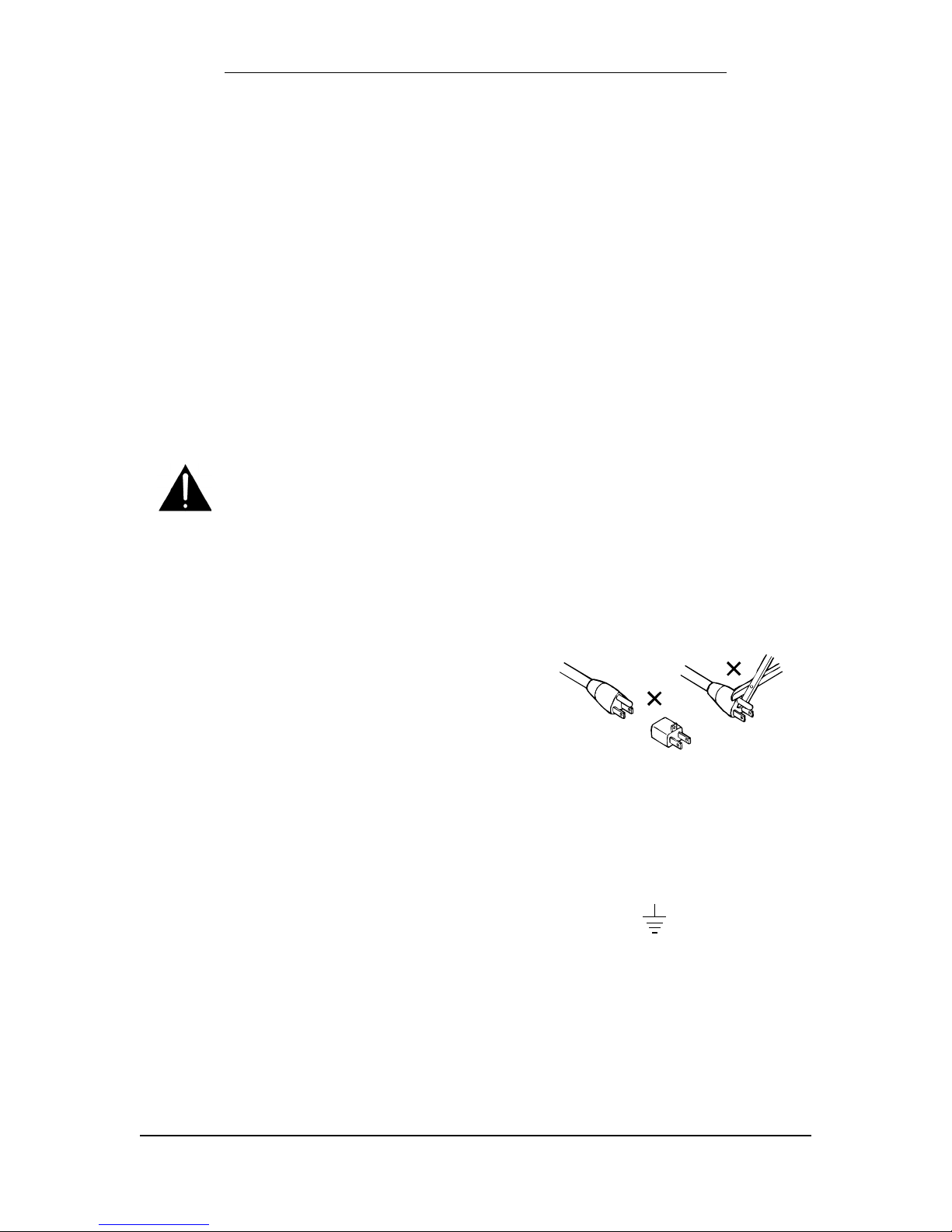
o Ensure fuses fitted are the correct rating and type as marked on the unit.
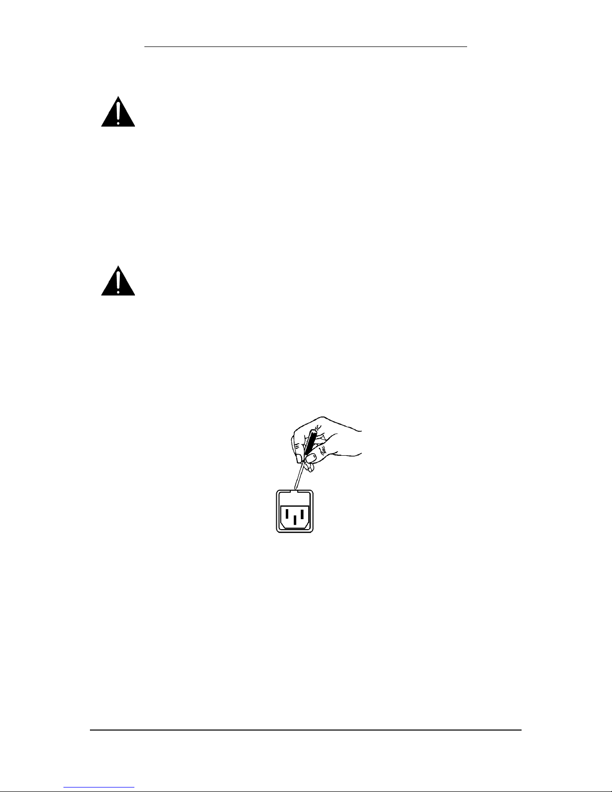
o The unit must be earthed by connecting to a correctly wired and earthed power outlet.
o The power cord supplied with this unit must be wired as follows:
Live—Brown Neutral—Blue Earth—Green/Yellow
IMPORTANT – NOTE DE SECURITE
Ce materiel est conforme à la norme EN60065. Ne pas exposer cet appareil aux éclaboussures
ou aux gouttes de liquide. Ne pas poser d'objets remplis de liquide, tels que des tasses de café,
sur l'appareil. Pour vous assurer d'un fonctionnement sans danger et de prévenir
tout choc électrique ou tout risque d'incendie, veillez à observer les recommandations suivantes.
o Le selecteur de tension doit être placé sur la valeur correspondante à votre alimentation
réseau.
o Les fusibles doivent correspondre à la valeur indiquée sur le materiel.
o Le materiel doit être correctement relié à la terre.
o Le cordon secteur livré avec le materiel doit être cablé de la manière suivante:
Phase—Brun Neutre—Bleu Terre—Vert/Jaune
WICHTIGER SICHERHEITSHINWEIS
Dieses Gerät entspricht der Sicherheitsnorm EN60065. Das Gerät darf nicht mit Flüssigkeiten
(Spritzwasser usw.) in Berührung kommen; stellen Sie keine Gefäße, z.B. Kaffeetassen, auf das
Gerät. Für das sichere Funktionieren des Gerätes und zur Unfallverhütung (elektrischer Schlag,
Feuer) sind die folgenden Regeln unbedingt einzuhalten:
o Der Spannungswähler muß auf Ihre Netzspannung eingestellt sein.
o Die Sicherungen müssen in Typ und Stromwert mit den Angaben auf dem Gerät
übereinstimmen.
o Die Erdung des Gerätes muß über eine geerdete Steckdose gewährleistet sein.
o Das mitgelieferte Netzkabel muß wie folgt verdrahtet werden:
Phase—braun Nulleiter—blau Erde—grün/gelb
NORME DI SICUREZZA – IMPORTANTE
Questa apparecchiatura è stata costruita in accordo alle norme di sicurezza EN60065. Il prodotto
non deve essere sottoposto a schizzi, spruzzi e gocciolamenti, e nessun tipo di oggetto riempito
con liquidi, come ad esempio tazze di caffè, deve essere appoggiato sul dispositivo. Per una
perfetta sicurezza ed al fine di evitare eventuali rischi di scossa êlettrica o d'incendio vanno
osservate le seguenti misure di sicurezza:
o Assicurarsi che il selettore di cambio tensione sia posizionato sul valore corretto.
o Assicurarsi che la portata ed il tipo di fusibili siano quelli prescritti dalla casa costruttrice.
o L'apparecchiatura deve avere un collegamento di messa a terra ben eseguito; anche la
connessione rete deve
avere un collegamento a terra.
o Il cavo di alimentazione a corredo dell'apparecchiatura deve essere collegato come segue:
Filo tensione—Marrone Neutro—Blu Massa—Verde/Giallo
#:?62C4@FDE:4)&=:E6)68F=2E@CJ ?7@C>2E:@?2?5FD:?8

AVISO IMPORTANTE DE SEGURIDAD
Esta unidad cumple con la norma de seguridad EN60065. La unidad no debe ser expuesta a
goteos o salpicaduras y no deben colocarse sobre el equipo recipientes con liquidos, como tazas
de cafe. Para asegurarse un funcionamiento seguro y prevenir cualquier posible peligro de
descarga o riesgo de incendio, se han de observar las siguientes precauciones:
o Asegúrese que el selector de tensión esté ajustado a la tensión correcta para su alimentación.
o Asegúrese que los fusibles colocados son del tipo y valor correctos, tal como se marca en la
unidad.
o La unidad debe ser puesta a tierra, conectándola a un conector de red correctamente
cableado y puesto a tierra.
o El cable de red suministrado con esta unidad, debe ser cableado como sigue:
Vivo—Marrón Neutro—Azul Tierra—Verde/Amarillo
VIKTIGA SÄKERHETSÅTGÄRDER!
Denna enhet uppfyller säkerhetsstandard EN60065. Enheten får ej utsättas för yttre åverkan
samt föremål innehållande vätska, såsom kaffemuggar, får ej placeras på utrustningen." För att
garantera säkerheten och gardera mot eventuell elchock eller brandrisk, måste följande
observeras:
o Kontrollera att spänningsväljaren är inställd på korrekt nätspänning.
o Konrollera att säkringarna är av rätt typ och för rätt strömstyrka så som anvisningarna på
enheten föreskriver.
o Enheten måste vara jordad genom anslutning till ett korrekt kopplat och jordat el-uttag.
o El-sladden som medföljer denna enhet måste kopplas enligt foljande:
Fas—Brun Neutral—Blå Jord—Grön/Gul
BELANGRIJK VEILIGHEIDS-VOORSCHRIFT:
Deze unit voldoet aan de EN60065 veiligheids-standaards. Dit apparaat mag niet worden
blootgesteld aan vocht. Vanwege het risico dat er druppels in het apparaat vallen, dient u er geen
vloeistoffen in bekers op te plaatsen. Voor een veilig gebruik en om het gevaar van electrische
schokken en het risico van brand te vermijden, dienen de volgende regels in acht te worden
genomen:
o Controleer of de spanningscaroussel op het juiste Voltage staat.
o Gebruik alleen zekeringen van de aangegeven typen en waarden.
o Aansluiting van de unit alleen aan een geaarde wandcontactdoos.
o De netkabel die met de unit wordt geleverd, moet als volgt worden aangesloten:
Fase—Bruin Nul—Blauw Aarde—Groen/eGel
#:?62C4@FDE:4)&=:E6)68F=2E@CJ ?7@C>2E:@?2?5FD:?8

WARNING: To reduce the risk of fire, replace fuses only with the
same type and rating.
Both units use a universal switching power supply that handles the full range of nominal
mains voltages between 90 and 264 VAC and any frequency between 50 Hz and 60 Hz.
Check Main Fuse
The Main fuse rating is T 1A L (1 Amp, 250 V, 20 mm, time-lag, low breaking capacity) for
all operating voltages.
WARNING: The power to the unit must be off when the
following steps are performed. Ensure that the main power
cable to the unit is not connected to a power source.
1. Open the fuse compartment door in the AC power input housing with a
small flat-blade screwdriver (Figure 1). Carefully pull out the fuse carrier.
2. Check that the replacement fuse has the correct rating. The fuse carrier
must be inserted into the compartment carefully. Do not force the carrier
into the compartment or both could be damaged.
3. Snap the fuse compartment door closed.
Figure 1 Checking the Main Fuse
Internal Fuse
The switching power supply contains a separate fuse. Most fault conditions should be
protected by the main fuse.
If you find it necessary to replace the internal fuse, be certain to replace it with a fuse of
the same type and rating as printed on the switching power supply board.
#:?62C4@FDE:4)&=:E6)68F=2E@CJ ?7@C>2E:@?2?5FD:?8

Chapter 1: Introduction and Overview
The Linear Acoustic AERO.lite™ is a compact stereo transmission loudness
controller for digital television audio, with the following features:
^AEROMAX® 2.0 channel multistage adaptive wideband and multiband
loudness control engine
^AES I/O with reference input
^Auto-sensing HD/SD-SDI inputs and access to all 16 audio channels
^Balanced +4dBu analog I/O and front panel headphone output
^Parallel GPI/O control port for alarms and control
^Flexible audio routing allows conversion between analog, AES, and SDI
^Internal auto-sensing power supply
^Utility ITU BS.1770 loudness meter (Optional)
^SNMP signaling (Optional)
^Backup external 12VDC supply (Optional)
1.1Principles of Operation
The AERO.lite is a simplified, 2-channel (stereo) version of the Linear Acoustic
AERO.one transmission loudness manager. It employs the same integrating long-
term loudness controller and multiband short-term loudness controllers found in the
AERO.lite and other AERO-series products.
Specific processing presets and adjustments are discussed in Chapter 4. Figure
1-1 shows the internal audio path of the AERO.lite.
1.2Location of AERO.lite
Audio processors can be placed in a variety of locations depending upon the
design of the transmission path. We recommend you keep the AERO.lite as near
to the final emission DTV encoder as possible, as the units work closely together
and will benefit from short cable runs and common clocking.
1.3Reference Levels
The AERO.lite is designed to support a standard reference level of -20dBFS via its
digital inputs. Analog inputs support nominal levels from +4dBu (nominal) to
+24dBu (maximum). Other levels are supported as the slow-moving Input AGC will
easily compensate for differences.
#:?62C4@FDE:4)&=:E6 ?EC@5F4E:@?2?5&G6CG:6H
3

Figure 1.1 AERO.lite Internal Audio Path
HD/ SD- SDI
Demux
48kHz
Int.
Rx
Rx
24-Bit
SRC
24-Bit
SRC
Aeromax
Loudness
DRC 2.0
SDI In
(HD/ SD)
Ref Sel
AES
AES
Ref
Analog
In
(XLR)
Input Set
Chan M ode
Stereo
Mono (1+ 2)
M ono 1 (1/ 1)
M ono 2 (2/ 2)
HD/ SD- SDI
M ux
Relay
Bypass
SD I - Out
(HD/ SD)
Receiver
& A/ D
D/ A &
Driver
D/ A &
Driver
Analog Out
(XLR)
Headphone Out
( V ia FP 6.3mm)
GPI Out
CPU
Internal
PSU
Ethernet
GPI In
90-264VAC
35W
1/ 2
M ain Out
SDI In
1-16
Analog
In
Proc
1/ 2
SDI
1-16
L
R
L
R
L
R
Relay
Bypass
ITU
M eter
(Opt.)
12VDC External PSU
(Opt.)
#:?62C4@FDE:4)&=:E6 ?EC@5F4E:@?2?5&G6CG:6H
4

Chapter 2: Connections and Quick Setup
Far be it for us to get in the way of you and compelling audio. We want you to get your
new AERO.lite up and running just as quickly as you do, and realize this is not the most
exciting portion of any user manual. However, being thorough and careful now can
prevent common issues related to improper installation later. Honest.
2.1Unpacking and Inspection
Before unpacking the unit, inspect the outer carton for shipping damage. We use
carefully designed shipping cartons and packing materials to protect our products during
shipment, but sometimes, bad things happen in transit. If the carton shows damage,
inspect the unit carefully in those areas.
In the unlikely even that the unit ever needs to be returned to to the factory, alternate
cartons and packing materials may not adequately protect the contents. Therefore, we
strongly encourage you to please save the original carton and packing materials.
In addition to a shiny new AERO.lite, we have also included a bag containing a quick-
start sheet to get you up and running, an IEC power cord (style matches country of
order), this manual, and the much sought-after Linear Acoustic Sharpie marker.
You’ll also find the much maligned warranty card, which nearly everyone keeps with the
manual (where it does neither you nor us any good). Please, keep your New Year’s
resolution to always do the right thing, fill out the card, and mail it in. It will allow us to get
in contact with you for software or documentation updates, and we promise only to use
the information for good, never evil. We won’t clog your actual or electronic mailboxes
with unsolicited stuff, and we’ll never, ever share your information. Alternatively, you may
FAX the card to us at +1-717-735-3612. Thank you in advance for helping us help you!
2.2Installation
AERO.lite installation requires:
^One standard rack space unit with ADEQUATE VENTILATION. The unit relies
on convection cooling from the side-panel vents).
^Standard 75-Ohm BNC cables for digital signal connections. To connect digital
equipment with 110-Ohm XLR connectors, use impedance-matching
transformers (available from Canare, Neutrik, and other manufacturers).
^Standard balanced XLR cables for analog signal connections.
^Proper reference. The unit provides an internal 48kHZ reference input, or it can
be synchronized to an external source via the AES Reference Input. All inputs
have Sample Rate Converters (SRC’s) but a master reference is required.
Proper reference signal selection and application is imperative for an artifact-free
installation. Clicks or pops in the audio can usually be traced back to improper
reference configuration.
#:?62C4@FDE:4)&=:E6@??64E:@?D2?5(F:4<*6EFA

2.3Rear Panel
The rear panel of the AERO.lite contains its electrical, signal, and control connections.
Specific pinout information for GPI I/O is provided in Chapter 5.
Figure 2-1 Rear Panel
RS-485 Connection
%@EFD652EE9:DE:>6
2.3.1 GPI/O
Connect dry contact closures here to for external control of certain functions. For
example, you may wish to set up a means to recall a “Bypass Processing” preset if EAS
is inserted ahead of the AERO.lite (though installing your EAS unit after the AERO.lite is
preferred). Note that GPI functions require held closures for the duration of the desired
function.
2.3.2 ETHERNET
10/100 BASE-T Network connection used for firmware upgrades and SNMP reporting.
2.3.3 SDI I/O
Permits de-embedding and re-embedding any of the 16 available channels in an applied
HD-SDI or SD-SDI signal.
NOTE: Appropriate reference must be applied AND selected for proper
operation. To aid in this critical setting, if SDI embedding is enabled, the
clock source will automatically be set to SDI.
2.3.4 AES I/O
Inputs and outputs for 75-Ohm digital audio input and output. Note that the sync
reference can be set to use this AES Input, or if the input signal is not referenced to the
plant or is at a rate other than 48kHz, select the AES or SDI reference.
2.3.5 AES Reference I/O
Use AES Reference I/O to resynchronize the AERO.lite to an external reference, and be
sure to choose AES Ref as the clock source in the Setup->I/O menu. Note that the AES
Reference output is active and is locked to the selected reference signal (Internal, SDI,
AES In, AES Ref In).
2.3.6 Analog I/O
Connect left- and right-channel analog Inputs and Outputs here. If you intend to use the
internally-generated 48kHz reference signal, the analog inputs and outputs can be
employed with no need for external reference signals.
#:?62C4@FDE:4)&=:E6@??64E:@?D2?5(F:4<*6EFA

2.3.7 Power
Connect the supplied IEC power cord to the internal power supply, and the (optional)
external 12VDC power supply to the Backup In connection.
NOTE: If using an alternate 12VDC power supply, it MUST be filtered
and regulated and have an output of +12VDC +/-5%. Any damage caused
by use of power supplies not provided by Linear Acoustic will not be
covered by the warranty.
2.4Quick Setup Notes
The Linear Acoustic AERO.lite is configured at the factory and arrives ready to go on the
air after making the proper input and output connections and establishing the proper I/O
and clock sync settings.
?Apply audio to the SDI, AES, AES Reference, or Analog inputs as appropriate for
your individual facilities.
?In the Setup->I/O menu, make sure the Input source corresponds to the type of
input employed on the rear panel.
?While in the Setup->I/O menu, be sure to choose the proper clock reference for
your application.
?Processed audio will be available on all audio outputs.
The best way to learn the AERO.lite is to explore its different settings with audio applied
and monitored. There are several factory presets to support many different applications
and tastes. Some presets may not sound much different at first, but will perform
differently depending on program content.
NOTE: For best audio quality, the AERO.lite should be the only
processor in line with station audio. Please make sure to remove any
legacy processing - especially anything that might be left over from
previous analog transmission operations - it will impair the performance of
the AERO.lite. We suggest checking station documentation and physical
installations to make sure the old gear has been removed.
#:?62C4@FDE:4)&=:E6@??64E:@?D2?5(F:4<*6EFA

Chapter 3: Detailed Operation and Menus
This chapter takes a detailed look at the layout and operation of the Linear Acoustic
AERO.lite. Included here are examples of the front panel display and descriptions of the
various menus.
As you explore, keep in mind that moving the joystick (menu knob) to the left will always
back you out toward the Main menu, turning the knob allows parameter adjustment, and
The menus and submenus are structured in such a way that more complex functions are
situated deeper into the hierarchy. A compact version of the menu tree is provided
below, though you may find it most helpful to study the larger, fold-out menu tree at the
end of this chapter and keep it handy as you navigate the AERO.lite for the first time.
Figure 3-1 Menu Tree
#:?62C4@FDE:4)&=:E66E2:=65&A6C2E:@?2?5$6?FD
8

3.1Main Menu (Signal Status Meters)
3.1.1 Audio Input/Output Meters and LKFS Display
Shows input and output audio levels on the left and right channels, and the current
loudness LKFS loudness measurements.
Figure 3-2 Input/Output Meters and LKFS Display
3.1.2 AGC/Processing Meters
Shows the amount of gain expansion or reduction of the wideband input AGC (W) and
each band of the multiband AGC’s (1-5). The stationary horizontal line in each band
represents 0dB - the center of the meter’s range. Meters above this line indicate
expansion; meters below it indicate compression (gain reduction). More downward
excursion of the meters represents more gain reduction is being applied.
Figure 3-3 Processing Meters
3.1.3 GPI Status Display
Shows the current status of each of the four General Purpose Inputs, plus the current
(active) preset.
Figure 3-4 GPI Status Display
3.1.4 GPO Status Display
Shows the current status of each of the four General Purpose outputs.
#:?62C4@FDE:4)&=:E66E2:=65&A6C2E:@?2?5$6?FD

3.2Statistics Menu
Provides detailed information about software, firmware and DSP versions, DSP
communications status, device options, SNMP errors and packet information, and the
presence of AES pairs 1-8, in the following order as you navigate downward in the
menu:
3.2.1 Firmware Version
Shows current firmware version.
3.2.2 Device Options
Available options can be viewed by turning the menu knob.
3.2.3 App Uptime
Shows time running since the last reboot.
3.2.4 Ref Chg
Counts the number of times the system reference has changed since last reboot or
reset. Moving the menu knob to the right resets the meter.
3.2.5 Reset LKFS
Shows the elapsed time since the last reset of the LKFS loudness meter. Moving the
menu knob to the right resets the meter.
3.2.6 SNMP Trap Err(or)s
Indicates the number of SNMP trap errors and the error codes. Moving the menu knob
to the right resets the meter.
3.2.7 SNMP Tx Errors
Shows the number of SNMP transmit errors and the error code. Moving the menu knob
to the right resets the meter.
3.2.8 SNMP Rx Errors
Shows the number of SNMP receive errors and the error code. Moving the menu knob
to the right resets the meter.
3.2.9 SNMP Pkt
Counts the number of trap, transmit, and receive packets since the last reboot or reset.
Moving the menu knob to the right resets all counts.
3.2.10 DSP 1 Version
Shows current DSP 1 version.
3.2.11 DSP 1 Tx Errors
Shows the number of transmit errors between micro and DSP 1 and the error codes.
Moving the menu knob to the right resets the meter.
3.2.12 DSP 1 Rx Errors
Shows the number of receive errors between micro and DSP 1 and the error codes.
Moving the menu knob to the right resets the meter.
#:?62C4@FDE:4)&=:E66E2:=65&A6C2E:@?2?5$6?FD

3.2.13 DSP 2 Version
Shows the current DSP 2 version.
3.2.14 DSP 2 Tx Errors
Shows the number of transmit errors between micro and DSP 1 and the error codes.
Moving the menu knob to the right resets the meter.
3.2.15 DSP 2 Rx Errors
Shows the number of receive errors between micro and DSP 1 and the error codes.
Moving the menu knob to the right resets the meter.
3.2.16 AES In Detect
Shows the presence of an AES carrier on any of the 8 audio channels.
3.3Setup Menu
Entering the setup menu gives you access to several sub-menus, including the Presets,
I/O, Communication, and System menus.
Moving the menu knob down one step from the main Setup Menu takes you to the these
four sub-menus. Moving the menu knob left or right allows you to scroll between them.
Once you’ve entered one of the sub-menus, moving the menu knob up or down
navigates through the various functions of each.
Presets and processing are discussed in more detail in Chapter 4.
3.4 Presets Menu
3.4.1 User Preset
Shows the current (active) preset. Turning the menu knob scrolls through all available
factory and user presets. An asterisk (*) appears in the display as soon as you move
away from the currently employed preset. To put the preset on the air, move the menu
knob to the right.
Moving the menu knob down from the User Preset menu provides access to the Input
AGC, Multiband AGC, Multiband levels, Final Stage level, and the Preset Name editor.
Please see Chapter 4 for a complete explanation of the processing menus.
3.5I/O Menu
The Input/Output menu is where input and output audio are selected to interface with the
loudness control (processing) engine.
3.5.1 Master Bypass
When enabled, de-energizes the audio and SDI relays for a hard bypass. This will
create a brief interruption of these signals, and is a feature primarily designed for
troubleshooting.
#:?62C4@FDE:4)&=:E66E2:=65&A6C2E:@?2?5$6?FD

3.5.2 GPI Control
When enabled, the unit is under GPI control and most front-panel controls are disabled.
You will also see a “g” in the left corner of the display indicating GPI control is active.
3.5.3 GPI Function (GPI 1-4
Selects the function of each GPI input. Selections are:
?None: No function has been assigned for this GPI (as you may have guessed)
?Preset: GPI selects a preset.
?Reset LKFS: Resets the LKFS loudness meter.
3.5.4 GPI Preset (GPI 1-4)
Defines which of the stored presets a GPI will recall. Any factory or user preset can be
recalled by GPI.
3.5.5 Channel Mode
Determines whether the output will be Stereo, Mono (L and R inputs combined in both L
and R outputs), Mono Ch 1 (L channel input present at both L and R outputs), Mono Ch
2 (R channel input present at both L and R outputs). An asterisk (*) appears in the
display as soon as you move away from the current setting. To put a new configuration
on the air, move the menu knob to the right.
3.5.6 SRC Bypass
When enabled, bypasses the Sample Rate Converters. If the AERO.lite is synchronized
to incoming signals and plant reference, there is no reason for the SRCs to be in line,
and bypassing them will lower latency by about 3 milliseconds.
3.5.7 Headphone Boost
When enabled, increases the output level of the front panel headphone jack by 12dB.
This enables very low-level audio to be heard. CAUTION: The headphone output can
get LOUD, please use this selection carefully.
3.5.8 Clock SRC Type
The default selection of “Stable” is intended for external clock sources which are stable
and unlikely to be disturbed (i.e. via asynchronous “crash” switching). If the chosen
reference is regularly interrupted (yes, we know) then select “Changing” which enables a
faster recovery from such disturbances.
3.5.9 Clock Source
Select SDI input, AES Input 1, AES Reference input, or Internal 48kHz (only for analog
or stand-alone use).
#:?62C4@FDE:4)&=:E66E2:=65&A6C2E:@?2?5$6?FD
Table of contents
Other Linear Acoustic Recording Equipment manuals
Popular Recording Equipment manuals by other brands

DMX4ALL
DMX4ALL DMX-Relais/Analog Interface 4 user manual

Denon
Denon Hs 5500 - Dn - Direct Drive Turntable Media... Midi specifications

AOR
AOR ARD9800 Instruction manua

Extron electronics
Extron electronics RGB 160xi user manual

Rockwell Automation
Rockwell Automation AllenBradley 432ES-IG3 user manual

Xaoc Devices
Xaoc Devices Tirana Operator's manual