CATHEXIS EIO-3148 User manual

005-20151112-75 Rev 2 February 2, 2016 matthew brecher
EIO-3148 Manual

005-20151112-75 Rev 2 February 2, 2016 Page 1
Contents
1 Introduction .....................................................................................................................................................2
a. Specifications................................................................................................................................................2
b. Summary.......................................................................................................................................................2
c. Alarm Inputs .................................................................................................................................................3
d. Relay Outputs (non-polarised) .....................................................................................................................3
e. Opto-isolator ................................................................................................................................................4
f. Hardware requirements ...............................................................................................................................4
g. Physical requirements ..................................................................................................................................4
h. Software requirements.................................................................................................................................5
i. Network requirements .................................................................................................................................5
j. Connector Layout and LEDs..........................................................................................................................5
2 Encoder Setup ..................................................................................................................................................7
a. The CatEncoderSetup Interface....................................................................................................................7
b. Set Encoder IP Address/s with the CatEncoderSetup utility ........................................................................9
3 CathexisVision Setup ......................................................................................................................................11
a. Open the Network I/O Setup......................................................................................................................11
b. Add/Edit an EIO-3148 .................................................................................................................................11
c. Default Input State Setup ...........................................................................................................................12

005-20151112-75 Rev 2 February 2, 2016 Page 2
1Introduction
The EIO-3148 network base IO
expander device enables
comprehensive access and control
of remote opto-isolated inputs and
non-polarised outputs over an
Ethernet network. In applications
where an Ethernet network
already exists, this is a significant
cost-saver as it does away with the
requirement for cabling. Through
the CathexisVision software
control, opening and closing of
integrated relay contacts can be
incorporated into any response of
a critical event.
a. Specifications
Ethernet interface
1
Ethernet specification
Class 4 PoE+ (15 W)
The unit may be powered via POE, as per the above specification.
Relay (non-polarised)
outputs
4
Opto-isolated inputs
8
Input Interface
Isolated inputs sense contact open or closed.
Input Isolation
2500 V rms for 1 minute, per UL 1577
Contact material
Ag Au clad, AgNi Au clad
Contact rating
0.5A/125VAC, 1A/30VDC, 0.3A/60VDC
Maximum carrying current
Contact Rating (Res. load): 0.5A/125VAC, 1A/30VDC, 0.3A/60VDC
Maximum switching
power
30W 62.5VA
Maximum switching
voltage
See Contact Rating
Power Consumption
5 Watts
Supply Voltage
9-36V DC and is protected against the application of incorrect polarity.
Software
CathexisVision 2016. Backwards compatible with previous releases that support
the EIO-1148 (on which it will function as an EIO-1148).
Physical dimensions
145x107x28 (w x l x h)
Mounting options
Flanges with 2x slotted mounting holes, and DIN rail mounting option.
Enclosure / Environment
High temperature, ROHS compliant, plastic housing.
The enclosure is not waterproof, and should only be installed indoors.
Maximum EIO-3148
encoders per NVR
32
b. Summary
This encoder has 8 opto-isolated alarm inputs and four relay (non-polarised) outputs. The encoder is powered
by a 9 to 32 VDC power source. It sends and receives data via an Ethernet cable connected to a network.

005-20151112-75 Rev 2 February 2, 2016 Page 3
These encoders are fully integrated within the NVR software, with up to 32 EIO-3148 encoders possible per
NVR unit. Setup and operation is by means of CathexisVision software. The unit IP addresses and firmware are
manageable via the CathexisVision Encoder Utility.
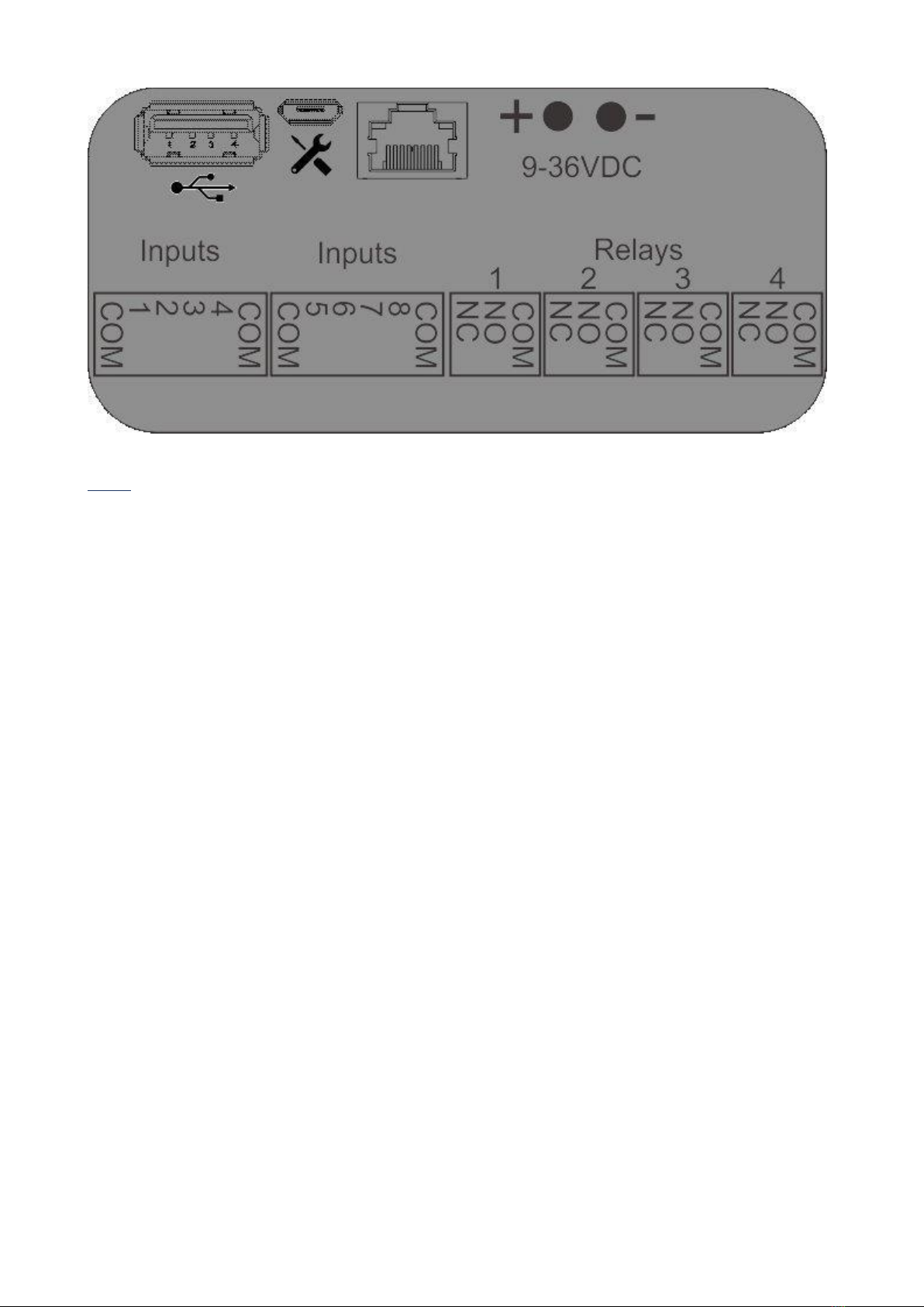
c. Alarm Inputs
Each EIO-3148 encoder has 8 opto-isolated alarm inputs that may be used to trigger automated system
responses.
A relay is an electrical switch that opens and closes under the control of another electrical circuit.
CathexisVision can treat the switching of these states as an Event action, and reacts with multiple possible
event actions.
The input is a signal indicating to the system that a change has taken place and requires a response.
Each input has two terminals that can be closed by means of the switch.
Examples of Alarm Inputs
Anything that can be switched can be treated as an alarm input.
Panic buttons - pressed by someone who needs help.
Passive Infrared (PIR) sensors - invisible infrared beams that cause switching when broken.
Other examples include magnetic loops, pressure pads, and door switches.
d. Relay Outputs (non-polarised)
Each EIO-3148 encoder has four non-polarised relay outputs, which may be used to switch wired utilities such
as door relays, lights alarms, etc.
A relay is an electrical switch that opens and closes under the control of another electrical circuit. In the case
of the EIO-3148, the opening and closing of the relays is controlled by CathexisVision in two possible ways:
1. Manually by an operator (e.g. manually switch on the facility floodlights when investigating an alarm),
or;
2. Automatically, as an event action in response to an event trigger (e.g. switch on a passageway light
when there is movement in the passageway).
Note:You need to connect a voltage source in series with your output device and the relay contacts. Devices
usually require an independent electrical source.
Examples of Relay Outputs
•Sirens and buzzers.
•Indicator lamps.
•Solenoid door locks –used a lot by receptionists, who can look at Live camera display of a door, and
then open the door from the CathexisVision user interface.
•Lights.
•Audio recordings –for example, an audio message in response to someone pressing a buzzer after
hours.
•Almost any electrical device.

005-20151112-75 Rev 2 February 2, 2016 Page 4
You could connect a relay output to an alarm input, and configure the input as an event trigger to trigger
multiple Event actions. In this way you would have a manual means of triggering automated CathexisVision
Event actions.
e. Opto-isolator
To protect the internal devices from external voltage spikes and harmful signals an opto-isolator is used to
separate the external current from the internal electronics.
It uses a short optical transmission path to transfer a signal between elements of a circuit, typically a
transmitter and a receiver, while keeping them electrically isolated —since the signal goes from an electrical
signal to an optical signal back to an electrical signal, electrical contact along the path is broken.
A schematic of an extremely simple opto-isolator device. The dashed line in the centre represents the isolation barrier,
over which no electrical contact can be permitted.
f. Hardware requirements
Power Sourcing Equipment
9 to 32 VDC source (ensure power cables are correctly connected example + to
+, - to -).
Full duplex switch
A switch that can handle a duplex communication system that is composed of
two connected devices that can communicate with one another in both
directions.
Single or multiple Cathexis
NVRs.
This will vary depending on your site.
Category 6 Ethernet Cable
(recommended)
Commonly referred to as “Cat-6”, this is a cable standard for Gigabit Ethernet
and other network protocols that is backward compatible with the Category
5/5e and Category 3 cable standards. Cat-6 features more rigorous
specifications for crosstalk and system noise. The cable standard provides
performance of up to 250 MHz and is suitable for 10BASE-T / 100BASE-TX and
1000BASE-T (Gigabit Ethernet). Category 6 cables can be identified by the
printing on the side of the cable sheath.
g. Physical requirements
1. For mounting consideration, the EIO-3148 is relatively small, light and robust, with dimensions
145x107x28 (w x l x h) mm.
2. If the EIO-3148 encoder is installed outdoors, it should be placed in a 3rd party enclosure because it is not
weatherproof.
3. The encoder is not designed for mobile applications, so it should be subjected to no more than transitory
shock during transportation.
4. For mounting, it has flanges.

005-20151112-75 Rev 2 February 2, 2016 Page 5
h. Software requirements
Each Encoder / IP camera requires an IP Address on the network. This can be assigned by means of the
Encoder Setup Utility .
CathexisVision 2016. While this device is backward compatible with pre-CathexisVision 2016 systems, it
will only function as an EIO-1148 on the 2016 system.
i. Network requirements
The network topology must be thoroughly understood, and the effects of the encoders on network
performance well considered before any decisions are taken on installing encoders.
j. Connector Layout and LEDs
Power LED
Connection Status LED
Micro USB connection, for debugging
USB connection for future use
DC Power Input
Ethernet, network and POE input
Reset Button
Front and Back Panel Layout
The connections on the front, and back, panel of the EIO-3148 are as such:

005-20151112-75 Rev 2 February 2, 2016 Page 6
LEDs
There are two LEDs on the EIO-3148.
Red LED: While the unit is booting the red led will flash on for 2s, then off for 0.5s. Once the unit is booted,
and the software is running, the red LED stays on.
Green LED: the green led will flash on 1s and off 1s while the software is running.

005-20151112-75 Rev 2 February 2, 2016 Page 7
2Encoder Setup
Before you can add your EIO to CathexisVision you need to be able to find it. Each unit has its own IP address
which identifies it on the network. The EIO will also need to have the right firmware. These setups can be done
via the CatEncoder Setup Utility. This is a separate application, which is installed when you install
CathexisVision.
The CathexisVision Encoder IP Utility has a number of features, which are useful in setting up your EIO:
1. Automatically searches the local physical network (behind firewall and/or router) and lists all
CatEncoders on the network.
2. Indicates connection status for each CatEncoder.
3. Automatically lists all CatEncoders on the local network.
4. Displays Format (NTSC or PAL, where applicable).
5. Displays the IP address of each CatEncoder.
6. Displays the local Gateway IP address for each CatEncoder.
7. Displays the subnet of each CatEncoder.
8. Displays each CatEncoder’s MAC address, and whether it is valid.
9. Displays each CatEncoder’s Firmware version.
10. Displays each CatEncoder’s current Temperature.
11. Displays the current task being performed by each CatEncoder.
12. Displays messages per CatEncoder (e.g. “connected”, “20% completed”, “failed”).
13. Displays alarm messages per CatEncoder (e.g. connection “Missing”, connection “Lost”, “MAC
Invalid”).
14. Multiple IP Address assignment from the interface, without the need to power-cycle CatEncoders.
15. Multiple firmware-updates from the interface, without the need to power-cycle.
The core features that will be used here are Setting the unit’s IP address, and upgrading the firmware, if
necessary.
a. The CatEncoderSetup Interface
Run the utility; after a few seconds you will see the interface with a list of all CatEncoders that it recognises:
Icons
A green icon indicates a functional connection.
The connection status is derived from the utility
polling (pinging) the network.
When it receives no response from an encoder, it
displays a yellow icon for that encoder for 30
seconds, until the next ping. If still no response, it
displays a red icon for 30 seconds, until the next
ping. If still no response, it drops the encoder from
the list.
You can also manually poll / ping / refresh (right-
click > Refresh).
A yellow icon indicates that the connection is
missing.
Under the alarm column, you will simultaneously
see the word “missing”.
A red icon indicates that the connection is lost.
Under the alarm column, you will simultaneously
see the word “Lost”.

005-20151112-75 Rev 2 February 2, 2016 Page 8
Menus
File Menu
The file menu item provides access to maintenance functions for
the CatEncoders that have been selected in the list.
Note: These functions are also accessible by right clicking on the
selected encoders.
View Menu
View>Columns is the means of hiding-and-showing columns:
Select (tick) to show, and de-select to hide columns.
By default, the Gateway, Subnet, MAC addresses, and
Temperatures are hidden.
The Temperature column displays current temperature of the
encoder.
The Firmware column shows the firmware details.
The Master column displays the IP address of the NVR/DVR unit
that is connected to the Encoder, the Master Controller. (This only
works on Firmware versions up to and including 5042d5.)
The Task, Messages and Alarm columns cannot be hidden.
Options:
Refresh
options Menu
Pings the listed encoders , updates the information.
Enable timeout
Tick this to enable a random timeout of up to 10
seconds, for spreading encoder ping responses (to
avoid all encoders responding simultaneously to ping
queries, this enables them to randomly respond to a
ping query within a 10s period).
Enable unicast
This enables the encoder to respond to the unicast
address from where the initial broadcast originated.
Max timeout (s)
Specifies the period within which successive pings
(refresh queries) should occur.
Help Menu
Click Help>About to display the Software version of the CatEncoderSetup.
Click Help>Help to display the Help file.
Columns
Serial number
As manufactured.
Format
The format of the video (E.G. PAL, NTSC).
IP
IP Address. This can be individually changed, or you can simultaneously change multiple
encoder IP addresses.
Gateway
The software automatically identifies the gateway for this local physical network.
Subnet
The software automatically identifies the subnet mask/s used.
MAC
The encoder’s MAC address.

005-20151112-75 Rev 2 February 2, 2016 Page 9
Note: if this is invalid, you will see a “MAC invalid” alarm under the Alarm column.
When booting an encoder in its factory default, you will see this alarm, but can ignore it.
Firmware
Here you will either see the firmware version (for the SAM3) units, or the firmware code (for
older units).
Temperature
Current temperature of the encoder.
Task
The current task being performed by the encoder. e.g. “Setting IP”, “Upgrading firmware”.
Messages
Further information relating to the task. e.g. “45% complete”, “connected”, “failed”.
Alarm
Indicator (in red text) of technical dysfunction. e.g. Missing, Lost, MAC invalid, Could not
connect, Could not open upgrade file, Unit already connected to [IP address].
MAC invalid: When booting an encoder in its factory default, you will see this alarm. This is
standard, and should be ignored. Once you have reprogrammed the encoder (updated
firmware) in default, and then restarted normally, the message will disappear.
File Menu and Right Click Options.
Right-click
menu
Set IP
See Set Encoder IP Address/s with the CatEncoderSetup utility (below).
Upgrade
firmware
IMPORTANT:
Please contact support for the upgrading of this device’s firmware.
Refresh
Pings the listed encoders and updates the information.
Enable timeout
Tick this to enable a random timeout of up to 10 seconds for spreading encoder ping
responses (to avoid all encoders responding simultaneously to ping queries, this enables them
to randomly respond to a ping query within a 10s period).
Enable unicast
This enables the encoder to respond to the unicast address from where the initial broadcast
originated.
Max timeout (s)
Specifies the period within which successive pings (refresh queries) should occur.
b. Set Encoder IP Address/s with the CatEncoderSetup utility
Note: The utility will only pick up encoders that are on the same network as the computer that is running the
utility.

005-20151112-75 Rev 2 February 2, 2016 Page 10
Set a single CatEncoder IP address
1.
Ensure that the Task column does not show “Program” (indicating a firmware upgrade in progress).
Note: If you attempt to change IP Address during a firmware upgrade; 1) the IP address will change, 2) the
connection will drop, 3) the firmware update process will be interrupted, and will have to be re-started,
and 4) if you power off at this point, the encoder will lose its configuration and have to be factory
defaulted, and then re-programmed (firmware-updated).
2.
Click to select the CatEncoder, then right-click it (or click the File
menu), and select “Set IP”, and select “Set Unit IP”, to display
the “Single IP” window:
3.
Change the “Unit IP” to the new IP address.
4.
If necessary, also modify the “Subnet” and “Gateway” fields.
5.
Click “OK”.
6.
The list refreshes itself approximately every 2 seconds –once refreshed, check that the encoder is now
displaying the new details.
Set multiple IP Addresses simultaneously
1.
Ensure that the Task column does not show “Program” (indicating a firmware upgrade in progress) against
any of these CatEncoders.
Note: If you attempt to change IP Address during a firmware upgrade; 1) the IP address will change, 2) the
connection will drop, 3) the firmware update process will be interrupted, and will have to be re-started,
and 4) if you power off at this point, the encoder will lose its configuration and have to be factory
defaulted, and then re-programmed (firmware-updated).
2.
Select multiple CatEncoders (use Shift-click or CTRL-click).
3.
Right-click, and select “Set Multiple IPs” from the menu, to display the “Multiple IPs” window:
4.
Anticipating an automatic series of IP addresses, re-order the listed CatEncoders:
4.1.
Select a CatEncoder.
4.2.
Use the up and down arrows to move it to a new position in the list.
4.3.
Repeat this process until you have the CatEncoders listed in the series that you require.
5.
Change the “Start IP” to the first IP address of the series that you require. You will immediately see the
new list of IP addresses under the “New IP” column, in numerical order.
6.
If necessary, also modify the “Subnet” and “Gateway” fields.
7.
Check that all is correct and then click “OK”.
Troubleshoot IP Address assignment
If the process fails, an error message will inform you to troubleshoot:
1. Right-click the encoder and select Reboot Unit to reboot the associated NVR.
2. Attempt the procedure again. If this fails, contact the Support Desk.

005-20151112-75 Rev 2 February 2, 2016 Page 11
3CathexisVision Setup
To setup an EIO-3148 in the CathexisVision software follow these steps.
Note: This unit is designed to work with CathexisVision 2016 and onwards. On earlier software versions it will
function as an EIO-1148, and will be setup as such.
a. Open the Network I/O Setup
First Open Your Site
File Open Site site_Name
Then Open the Setup Tab for that Site
Site Open Tab Setup
Open the Network I/O Setup
File Your_Site_Name Open Tab Setup Server
.
b. Add/Edit an EIO-3148
To Add/Edit an EIO-3128 click on one of the options at the base of
the Network I/O panel.
After clicking on New/Edit the setup dialogue will open. There are two tabs, the Settings tab and the I/O tab.
Settings Tab
Select the relevant Type from the drop-down menu.
Give the unit a descriptive name.
Fill in the IP address which was assigned via the Encoder setup utility
(see the previous section).
Fill in the login details. (default username = admin, default password =
admin).

005-20151112-75 Rev 2 February 2, 2016 Page 12
I/O Tab
The I/O tab is where the user may
define certain aspects of the Inputs
and Outputs.
Inputs
The inputs may be
enabled/disabled, as well as
named.
Outputs
The outputs may be
enabled/disabled, and named.
The user may also control an
output from this panel with the
following options:
The user may also set the output’s
pulse duration.
c. Default Input State Setup
The input states are high when the device is connected. When disconnected the input states show as
Unknown; CathexisVision sees this unknown state as low by default. If you have an event set up using one of
the EIO3148's inputs to trigger when its state is low, the event will trigger when the device is connected again,
as the state goes from low back to high. To resolve this, do the following:
Enable Debug Mode and Enter Advanced Setup
Note: This must be done on the server (this cannot be done from a client)
1. Once on a server, enter the Setup Tab, and press SHIFT+ALT+d.
2. Navigate to the Configure Servers section. (Make sure to do this after taking the first step.)
3. Expand the Advanced section.
Once you have entered the advanced section select the Inputs option. In the Inputs Panel
to the right, Right-click the inputs in question

005-20151112-75 Rev 2 February 2, 2016 Page 13
Either change the Set state when unknown option to high;
or select the Use last known state when unknown.
Table of contents
Other CATHEXIS Recording Equipment manuals
Popular Recording Equipment manuals by other brands

Alber
Alber neodrives SimplyRemote user manual

swissonic
swissonic USB Studio D Mk. II operating manual

Humandata
Humandata USB-204 user manual

pathway
pathway eDIN 1006 manual

METRObility Optical Systems
METRObility Optical Systems twister T1 Installation & user guide

MTHTrains
MTHTrains DCS Proto 2 Sound AIU Operator's manual