KBR multisys D2-ESET/MSMT-4 User manual

25833_EDEBDA0290-4620-1_EN
User Manual
Technical Parameters
multisys D2-ESET/MSMT-4
multisys D2-BSET-4
System IEnglish
Interfaces for
KBR eBus and module bus
You will nd the relevant instructions for KBR
devices in our Download Center.
https://www.kbr.de/de/dienstleistungen/
download-center

V4.00
25833_EDEBDA0290-4620-1_EN
2
KBR Kompensationsanlagenbau GmbH does not accept any liability for any loss or dam-
age resulting from printing errors in or changes to this manual.
In addition, KBR Kompensationsanlagenbau GmbH does not accept any liability for any
loss or damage caused by defective devices or devices manipulated by the user.
Copyright 2020 by KBR Kompensationsanlagenbau GmbH
Subject to change.
Table of contents

V4.00
25833_EDEBDA0290-4620-1_EN
3
1 Introduction......................................................................................................................................4
1.1 User manual ......................................................................................................................................4
1.2 Safety keys.........................................................................................................................................5
1.3 Safety notes....................................................................................................................................... 6
1.4 Product liability................................................................................................................................7
1.5 Disposal ..............................................................................................................................................7
1.6 Overvoltage and lightning protection....................................................................................7
2 multisys D2-ESET/MSMT-4 and multisys D2-BSET-4 General..........................................8
2.1 Connection diagram......................................................................................................................9
3 Hardware Conguration.............................................................................................................10
3.1 RS485 Interface and LAN ...........................................................................................................10
3.2 LAN and KBR Module Bus Interfaces (multisys D2-BSET-4)............................................11
4 Software conguration...............................................................................................................12
4.1 Assigning an IP Address to a Device of which
the Address is Not in the Address Range of the Network ..............................................13
4.2. E-port Conguration for eBus TCP ..........................................................................................15
4.3 Box-to-Box Operation (parameters of the master): ..........................................................17
4.4. E-port conguration for Modbus TCP ...................................................................................18
5 Technical Data ................................................................................................................................20
5.1 Power supply ..................................................................................................................................20
5.2 Electrical Connection...................................................................................................................20
5.3 Mechanical data ............................................................................................................................20
5.4 Standards and miscellaneous...................................................................................................21
Table of contents
Table of contents

V4.00
25833_EDEBDA0290-4620-1_EN
4
1 Introduction
Thank you for choosing this KBR quality product.
To become familiar with the operation and programming of the device and to use the
full range of functions of this high-quality product at all times, you should read this user
manual carefully.
The individual chapters explain the technical details of the device and show how damage
can be avoided through proper installation and commissioning.
1.1 User manual
This user manual must be accessible to the user at all times (e.g. in the switchgear
cabinet). Even if the device is resold to third parties, the manual remains an inherent
part of the device.
Although the utmost care has been taken in writing this user manual, errors may still
occur. We would be very grateful if you would notify us of any errors or unclear descrip-
tions you may notice.
Introduction

V4.00
25833_EDEBDA0290-4620-1_EN
5
1.2 Safety keys
This manual contains instructions that you must follow for your personal safety and to
avoid material damage. These instructions are identied by a warning sign or information
symbol, depending on the degree of hazard they warn about.
DANGEROUS VOLTAGE
"Warning" means that death, major injuries or damage may occur if suitable safety pre-
cautions are not taken.
CAUTION
"Caution" means that minor injuries or damage may occur if the appropriate safety pre-
cautions are not taken.
NOTE
"Note" is an important piece of information on the product, its operation or the respec-
tive part of the user manual to which special reference is being made.
Disclaimer
The contents of this user manual have been carefully reviewed in terms of the hardware
and software described. However, deviations cannot be excluded and therefore com-
plete conformity cannot be guaranteed. The specications made in this user manual are
reviewed on a regular basis; any corrections required will be included in the next revision.
Introduction

V4.00
25833_EDEBDA0290-4620-1_EN
6
1.3 Safety notes
In order to prevent operating errors, device operation is kept as simple as possible.
This will enable you to start your device up quickly.
It is in your own interest to read the following safety instructions carefully. The applicable
DIN/VDE regulations must be observed during installation!
Power supply connection, setup and operation of the device must be performed by
qualied personnel only. Qualied personnel as dened in the safety notes in this user
manual are those authorized to set up, ground and mark devices, systems and circuits in
accordance with applicable standards and regulations.
To prevent re and electric shock, do not expose the device to rain or moisture!
Before connecting the device to the power supply, check whether the local power supply
conditions comply with the specications on the device nameplate.
CAUTION
Incorrectly connecting the device can damage it!
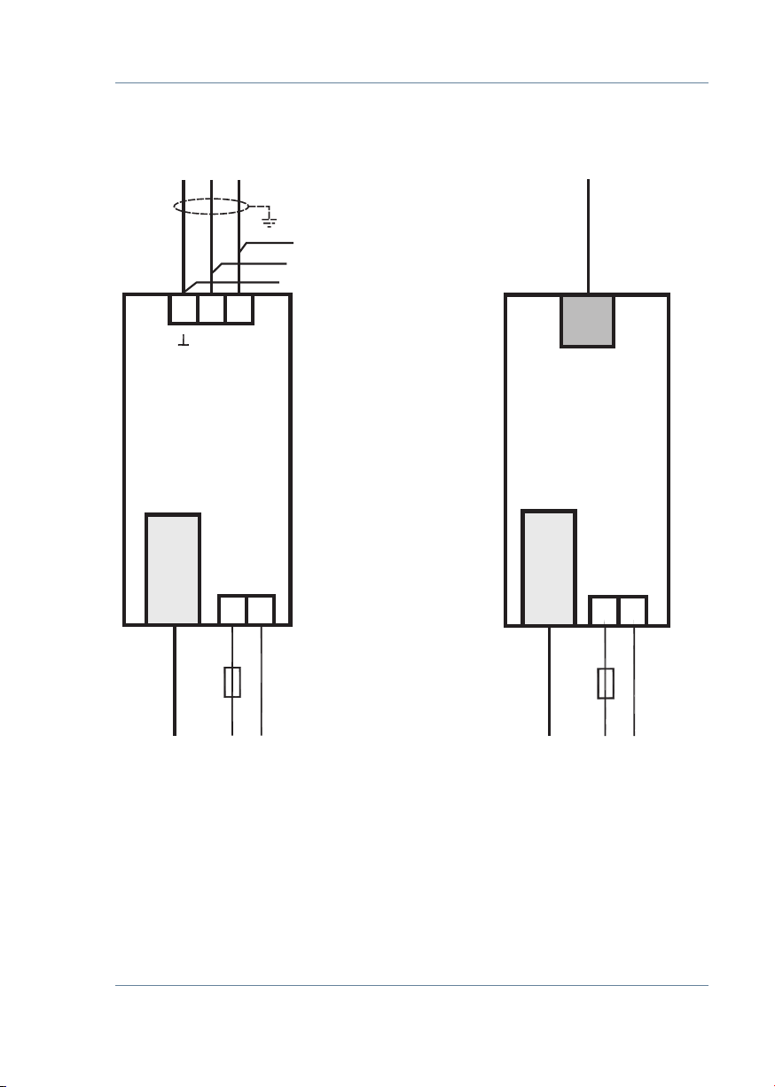
For device connection, the data given in the connection diagram must be complied with
(see chapter “Connection diagram”) and the connection lines must be voltage-free. When
wiring, always ensure that all wiring material used is neither damaged nor defective and
that the polarity is correct!
Proper and safe operation of the product requires correct transport, storage, installation
and assembly as well as careful operation and maintenance.
If the device has any visible damage it is considered unt for use and must be disconnect-
ed from the mains!
Troubleshooting, repairs and maintenance work may only be carried out at our plant or
after contacting our customer service team. If the device is opened without authoriza-
tion, any warranty or guarantee claim is forfeited. Correct functioning can no longer be
guaranteed!
Opening the device may expose live parts. Capacitors in the device may still be charged,
even if the device has been disconnected from all power sources. Do not operate open
devices under any circumstances!
Systems that are at risk from lightning strikes must feature lightning protection for all
input and output lines.
Introduction

V4.00
25833_EDEBDA0290-4620-1_EN
7
1.4 Product liability
You have purchased a high-quality product. Only top-quality components with
exceptional reliability are used.
Each device undergoes a long-term test before delivery.
With regard to product liability, please see our general terms and conditions for
electronic devices, which you can read at www.kbr.de.
The warranty on device characteristics only applies if the device is operated in
accordance with its intended use!
1.5 Disposal
Please dispose of defective, out-of-date or no longer used devices properly.
If required, we will dispose of the device for you.
1.6 Overvoltage and lightning protection
To protect your purchased high-quality devices from damage, we strongly recommend
that you take overvoltage protection measures. Protect control voltage inputs, pulse and
bus lines.
Introduction

V4.00
25833_EDEBDA0290-4620-1_EN
8
2 multisys D2-ESET/MSMT-4
and multisys D2-BSET-4 General
The multisys D2-ESET/MSMT-4 connects the KBR eBus to your computer via an Ethernet
connection.
- KBR eBus
- Modbus
On the Energy Bus side it acts as master and on the Ethernet side it acts as slave.
The two interfaces (RS-485 on the KBR eBus side, and Ethernet on the network side) are
galvanically separated.
The multisys D2-BSET-4 connects the KBR module bus to your computer through an
Ethernet connection.
On the Modbus side, it acts as master, and on the Ethernet side, it acts as slave.
The two interfaces (RS-485 on the module bus side, and Ethernet on the network side) are
galvanically separated.
The RS-485 interface on the KBR eBus or the module bus can be terminated if necessary,
using four DIP switches (terminating resistors are built into the multisys).
The device is equipped with a power LED for supply voltage monitoring.
The multisys D2-ESET/MSMT-4 and the multisys D2-BSET-4 each have a power sup-
ply (of <10VA; 100 - 240V ±10% DC/50/60 Hz) and are suitable for wall mounting on a
7.5mm-deep DIN rail in accordance with DIN EN50022 (for distribution board mounting).
NOTE
The Ethernet interface settings of the multisys D2-ESET/MSMT-4 and the multisys D2-
BSET-4 are identical.
General

V4.00
25833_EDEBDA0290-4620-1_EN
9
Both variations are described below.
2.1 Connection diagram
Connection diagram
F1
F1
2
NN
1
LL
Modulbus/
R 12 J
Modulbus
Module bus
90 92
91
multisys
D2-ESET/MSMT-4
LAN LAN
B
A
222
multisys
D2-BSET-4
zu weiterenTeilnehmern
bzw. Leitungsabschluss /
to other bus devices
and line termination
F1
Netz / power
21
Netz / power
TCP
TCP

V4.00
25833_EDEBDA0290-4620-1_EN
10
Interfaces LAN and KBR eBus RS-485
3 Hardware Conguration
3.1 RS485 Interface and LAN
The RS-485 interface is set to the KBR eBus parameters 38,400 baud, 8 data bits, parity
even, 1 stop bit. If necessary, it can be terminated using four DIP switches.
LAN
RS485
123
ON
SAB
4
Netz
LED for monitoring power supply
RJ-45 Ethernet connection
Power supply
<10VA; 100 - 240V ±10% DC/50/60 Hz
(2-pole multi-pin connector, 5 mm)
RS-485
(3-pole multi-pin connector, 3.5 mm)
Terminal no. 90 = Ground, 91 = A, 92 = B
(in accordance with KBR nomenclature)
DIP switch for terminating RS-485:
DIP1 and DIP2 ON, DIP3 OFF = failsafe activated
DIP1 and DIP2 OFF, DIP3 ON = termination activated
DIP1 and DIP2 OFF, DIP3 OFF= no failsafe,
no termination, DIP4 is not accounted for!
NOTE
The failsafe termination can only be activated once
per bus segment!

V4.00
25833_EDEBDA0290-4620-1_EN
11
Interfaces LAN and KBR module bus
LAN
RJ-12
123
ON
SAB
4
Netz
3.2 LAN and KBR Module Bus Interfaces (multisys D2-BSET-4)
The Modbus interface is set to the Modbus parameters 38,400 baud, 8 data bits, parity
even, 1 stop bit. If necessary, it can be terminated using four DIP switches.
LED for monitoring power supply
Power supply
<10VA; 100 - 240V ±10% DC/50/60 Hz
(2-pole multi-pin connector, 5 mm)
RJ-12 for the KBR module bus
DIP switch for terminating RJ-12:
DIP1 and DIP2 ON, DIP3 OFF = failsafe activated
DIP1 and DIP2 OFF, DIP3 ON = termination activated
DIP1 and DIP2 OFF, DIP3 OFF= no failsafe,
no termination, DIP4 is not accounted for!
NOTE
The failsafe termination can only be activated once
per bus segment!
RJ-45 Ethernet connection

V4.00
25833_EDEBDA0290-4620-1_EN
12
IOT ePort E20
4 Software conguration
Conguration is carried out using the IOT Service Tool. Supplier:
www.hi-ying.com/download-center-1/applications-1/download-item-iotservice
After installing and starting the IOT Service Tool, the connected network is scanned and
the e-ports found are displayed, and can be further processed.
After selecting the e-port, click on„Cong“ to access the conguration settings.
NOTE
The default settings are congured on the eBus. If Modbus is used, proceed as de-
scribed in Section 4.4.

V4.00
25833_EDEBDA0290-4620-1_EN
13
IOT ePort E20
4.1 Assigning an IP Address to a Device of which the Address is Not in
the Address Range of the Network
In the main window of the IOT Service Tool, open the ‘BroadCast Scan’ window via Setting
(C) -> BroadCast.
E-port devices that are in the network but do not have a valid network address are listed
here.
Double-click on the row with the device in it to open the‘Fast Setting’window:
NOTE
A valid IP address and the subnet mask can be entered here.
Click ‘Conrm’ to apply the settings.
The device should then appear in the list in the main‘IOT Service’window.

V4.00
25833_EDEBDA0290-4620-1_EN
14
IOT ePort E20
After selecting the e-port, click on„Cong“ to access the conguration settings.

V4.00
25833_EDEBDA0290-4620-1_EN
15
IOT ePort E20
4.2. E-port Conguration for eBus TCP
For eBus TCP, the parameters must be set as shown in the gure below. The network
parameters (IP address, mask, gateway, DNS) must be adapted to local circumstances.
NOTE
-„Flow Control: Half Duplex“ controls the changeover of RS-485 components.
- The local port must be set to 8000
- Click„Conrm“ to apply the parameters.

V4.00
25833_EDEBDA0290-4620-1_EN
16
IOT ePort E20
When„Detail“ is selected, this window appears:
NOTE
- For eBus TCP, the UART protocol must be set to‘NONE’
- The gap time should be set to 10 (ms). (This is the waiting time after serial reception,
until a telex message is sent via the network).
- Cli waiting time should be set to max. 15 (seconds)

V4.00
25833_EDEBDA0290-4620-1_EN
17
IOT ePort E20
4.3 Box-to-Box Operation (parameters of the master):
For this, the following settings are important:

V4.00
25833_EDEBDA0290-4620-1_EN
18
IOT ePort E20
4.4. E-port conguration for Modbus TCP
For Modbus TCP, the parameters must be set as shown in the gure below. The network
parameters (IP address, mask, gateway, DNS) must be adapted to local circumstances.
NOTE
The UART parameters must be adapted to the local bus parameters.
Local port: 502
Several connections to a serial interface, via the TCP, are possible.
Replies are only sent to the enquirer.

V4.00
25833_EDEBDA0290-4620-1_EN
19
IOT ePort E20
NOTE
Modbus ASCII cannot be congured.
Several connections to a serial interface, via the TCP, are possible. Replies are only sent to
the enquirer.

V4.00
25833_EDEBDA0290-4620-1_EN
20
Technical Data
5 Technical Data
5.1 Power supply
Power supply <10VA; 100 - 240V ±10% DC/50/60 Hz
5.2 Electrical Connection
Connection elements Plug-in terminals
Input control voltage Fuse max. 6 A
LAN connection 8P8C modular connector
BUS connection Connection
material
For proper operation,
use shielded twisted-pair cables
only; e.g. I-Y(St)Y2x2x0.8
BUS connection
multisys D2-ESET/MSMT-4
Pins for
BUS connection
via RS-485
Device
Terminal 90 ( )
Terminal 91 (A)
Terminal 92 (B)
BUS connection
multisys D2-BSET-4
6 pole modular cable,
RJ-12 connector: 6P6C
max. DC output power: 4 W
5.3 Mechanical data
DIN rail measuring device
Housing dimensions 90x36 x61mm (H x W x D),
Mounting type
Wall mounting on DIN rail 7.5 mm
deep, in accordance with
DIN EN 50022. Suitable for
distribution board mounting
Weight Approx. 120g
Other manuals for multisys D2-ESET/MSMT-4
1
This manual suits for next models
1
Table of contents
Other KBR Recording Equipment manuals