Dreadbox Dysphonia User manual

1. Construction
1.1 What's in the box 2
1.2 Bag parts 3
1.3 Tools you will use 3
1.4 Preparation of the bottom board 4
1.5 Preparation of the power board 5
1.6 Preparation of the top board 6
1.7 Connection of the top and bottom boards 10
1.8 Finalization of the module 16
2. Check, tune and calibrate
2.1 Check the assembled module 18
2.2 Tuning and calibrating the module 21
3. Operation manual
3.1 Oscillator 22
3.2 VCA 22
3.3 Multiple (MULTI) 22
3.4 Mixer 22
3.5 MIDI to CV/GATE 22
3.6 Modulator (MOD) 23
3.7 Envelope (ENV) 24
3.8 LFO 24
3.9 4-pole Low Pass Filter (LPF) 24
3.10 Multimode lter (12DB) 24
3.11 Echo 24
4. Specications 25
CONSTRUCTION
& OPERATION
Manual

1. Construction
1.1 What's in the box?
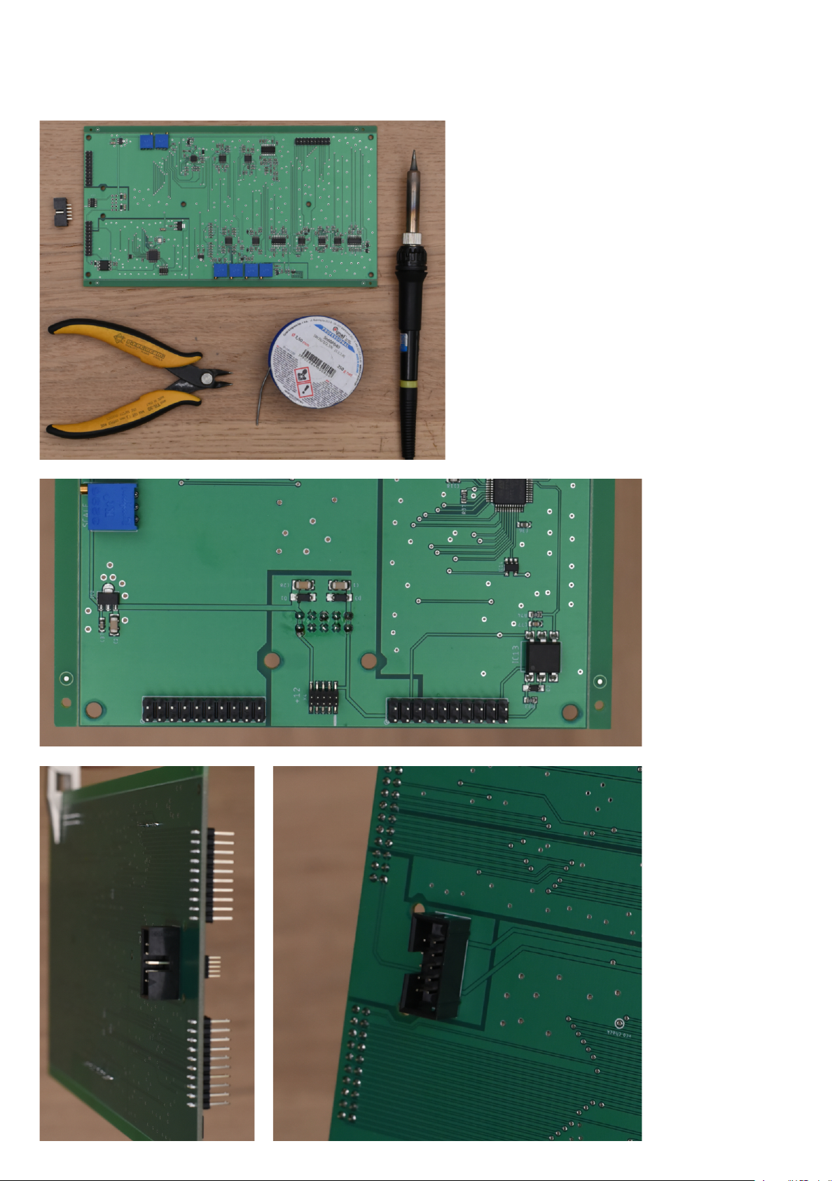
In the box you should nd the following items:
- The Bottom board, which is pre-assembled and tested in-house
(though you will still need to solder the ribbon header and tune it)
- The Top board
- The aluminum panel
- The power board
- The components bag
- A DIN5 (MIDI) to 3,5mm cable adapter (specs as suggested from MIDI.org)
- A ribbon cable for modular use (not shown in the picture)
BEFORE YOU GET STARTED
Before you start the construction of this DIY project, make sure you have basic soldering skills and that
you can identify the electronic components. If it is your rst time soldering, there are several tutorials
on youtube that can help you :)
It would be easier and helpful for you to work on a big desk, so as to have plenty of space to work on.
Also a room with an open window would be perfect while you soldering.
Before you start the soldering process, make sure you have all the components needed and noted in
the BILL OF MATERIALS SECTION. Please note that we might have added more components than
needed or less (hopefully not). It would be very helpful if you count all the components before starting
the project (but without removing these from their bags).
2

1.2 Components
1.3 Tools you will use
3
In the bag we've included all of the hardware parts
- 46 x 3,5mm stereo jack
- 13 x 100KB plastic rotary pot
- 8 x 10KB slider pot
- 2 x pushbutton with red LED
- 3 x female 20 pin connector headers
- 1 x female 10 pin connector header
- 1 x male 10pin ribbon connector header
- 1 x USB jack
- 8 x M3 Bolts with HEX head
- 6 x M3 bolts with Philips head
- 6 x M3 plastic spacer 16mm length
- 12 x M3 plastic spacer 11mm length
- 2 x M3 metal spacer 10mm length
- 2 x M3 washer 1mm heigh
The following tools are required for
this assembly, but they are not
included in the KIT
-Digital multimeter
-Soldering wire(0.7mm and 1.5mm)
-Soldering Iron
-Cutter
-Pliers

For this step you will need:
- The bottom board
- A Soldering iron
- 0.7mm solder wire
- A Cutter
- The 10pin ribbon male header
Solder the ribbon header to the
bottom side of the board as
shown in the pictures
4
1.4 Preparation of the bottom board

Then, cut the excess wires from the pre-assembled trimmers and remove the extra PCB from
the top and bottom side of the board.
1.5 Preparation of the power board
5
For this step you will need:
- The 0.7 solder wire + a soldering iron
- The USB jack
- The 10pin female header
Solder the USB jack and the header, as shown in the pictures.
You can also use this board as a generic modular power supply. Max supplied current is
200mA@+12V and 80mA@-12V. In order to do this, you need to solder a 16pin male
ribbon header (not included in the kit), instead of the 10pin female.
Pin "1" is marked with a small circle at the bottom right.

1.6 Preparation of the top board
Start by removing the excess PCB from the board
Locate and place the 3.5mm jacks on the board
Then solder these by using the 1.5mm wire
6

7
Next, locate the two push buttons.
WARNING! They have a polarity that needs to be
respected! If not placed correctly they will be
damaged and removing them is a challenging task!
Check their bottom side. The "+" sign should match
the square pad on the PCB.
Another tip on how to place them correctly is :
The guide on the top should match the small hole
on the PCB, and the long middle lead should match
the cycle pad.
Once you are sure regarding their orientation, push them rmly down to their position.
WARNING!: If the button is not pushed correctly, it will touch the aluminum panel and this will
not allow it to rest to it's OFF position - or it will not be able to be aligned correctly to the whole
of the panel.

8
The next step is to solder the slider
potentiometers.
Locate all 8 sliders and
place them on the pcb.
The proper way to solder the sliders
straight, is to solder the top pin from
the top side of the pcb. Then turn the
pcb upside down and reow the rest
pins. Make sure they are placed
correctly.
Make sure you have not set the
soldering iron above 350 degrees.
Also do not heat each slider pin for
more than 5 sec each time.
Do not try to adjust the slider's lever
while it is hot.

9
Finally, place the rotary
potentiometers on the pcb.
WARNING!: Make sure they are
perfectly straight! Otherwise they
will not be aligned correctly to their
corresponding hole on the panel!
Make sure you have not set the
soldering iron above 350 degrees.
Also do not heat each pot pin for
more than 5 sec each time.
Do not try to adjust the pot's lever
while it is hot.

10
1.7 Connection of the top and bottom boards
In this step we will connect the two boards and solder their connecting PIN headers.

11
Locate the 3x female 20pin headers.
Place them as shown in the pictures.
Make sure they are rmly attached to
their position.

Next, locate the following
parts:
- 2 x M3 HEX bolt
- 2 x M3 10mm metal
spacer
- 2 x M3 washer
These will be the base for
the power board.
If you are not going to use it
with the USB power board,
you should skip this step.
Place them as shown in the pictures:
- Hex bolt on the top side of the pcb, then place the washer to the other side and then add the
metal spacer. Bolt them rmly.
12

13
Now prepare the top board's spacer structure, so as to be able to connect the panel and the
bottom board. Find and place, as shown in the picture, the 12 pcs x 11mm plastic spacers.

Connect the Top and Bottom board as shown in the pictures.
Locate the 6pcs X 15mm plastic spacers.Then turn the assembly upside down and lock the
two boards by attaching the spacers as shown in the picture.
14

15
Finally, ip the assembly and solder with the 3 pin headers using the 0.7mm wire.
OPTIONAL
Remove R40, if you want a long delay time. Note though that as the repeats get longer,
their signal becomes very dirty.

16
1.8 Finalize the module
Place the aluminum panel as shown
in the picture.
Use the 6pcs x Hex bolts to attach it
into place.

Next, attach the power board as shown in the picture. If you are going to use it in a modular
case, skip this step.
By using a cutter, you can shorten the 16mm plastic spacer by cutting out the threaded part.
17
The module is completed and you should now move on to the tuning procedure.

2. Check, tune and calibrate
2.1 Check the assembled module
When the assembly of the module is complete, you should check that everything works. The following
steps will guide you through this process:
1. Power the unit. You should see a light sequence on the SET and TYPE buttons. After the sequence
stops, the TYPE LED should blink at the LFO rate (that is determined by the MOD RATE slider).
Connect a MIDI keyboard via the MIDI to 3.5mm adapter, that is provided in the kit.
Press the SET button. The LED will lit. Press any key on the MIDI keyboard and then press SET again.
Now your MIDI converter is set to your MIDI keyboard's channel.
If your unit does not power up for the rst time, do the following:
A. Unscrew the small power board.
B. Plug the power board alone in the USB supply.
C. While it's powered, connect it to the module.
After this procedure, your unit should power up normally.
If not, check the following:
A. Either your USB cable or power adapter are of a bad quality.
B. Your adapter cannot provide enough mA
C. You have done something wrong, during the assemble.
2. Do the following connections:
- CV OUT (placed in the MIDI to CV section) to OSCILLATOR CV IN (both CV IN are identical).
- SAW to a monitor or somewhere that you can get signal. WARNING!: this is a very high signal level!
- Adjust the OSCILLATOR TUNE at 0% and the FINE at 50%. Now observe the SAW signal. Play
some notes on the MIDI keyboard and make sure that the pitch changes. Play with the TUNE slider
and FINE knob and observe the pitch changes. Then check the TRI and SQU outputs. Finally check
the NOISE, which will not respond to the change of the pitch.
3. Remove the CV OUT to OSCILLATOR CV IN connection and then patch:
- MOD OUT to OSCILLATOR CV IN.
- Connect the SAW OUT to your monitor.
- Adjust the OSCILLATOR TUNE and FINE at 50%, MOD RATE 50%, MOD LVL at max. Observe the
change of the pitch. Move the MOD RATE slider and conrm that it works.
- Then press the TYPE button once. Move RATE up and down and set it at 50%. Observe the random LFO.
- Press the TYPE button again. Move RATE up and down and set it at 50%. Press any key on the
MIDI keyboard. Observe the envelope modulation.
- Press the TYPE button again. Move the Modulation wheel of the MIDI keyboard. Observe the
change of the pitch.
4. Remove the MOD OUT from the OSCILLATOR CV IN connection and then patch:
- The ENV OUT to the OSCILLATOR CV IN.
- The G OUT (placed in the MIDI to CV section) to the ENV TRIG IN.
- Set the FALL at 50% and the LVL at max. Press any key on the MIDI keyboard and observe the
change of the pitch.
5. Remove the ENV OUT from the OSCILLATOR CV IN and the G OUT from the ENV TRIG IN and
then Patch:
- The LFO OUT to the OSCILLATOR CV IN.
- Set the LFO RATE at 50% and the LVL at max and observe the pitch changes.
- Then set the MOD with the TYPE button on the LFO mode and patch the MOD OUT to the LFO CV.
Adjust the MOD RATE at 50% and observe the change of the pitch.
18

6. Remove all patches and connections so that the panel is clear. Now connect and set:
- the SAW to the LPF IN
- the LPF OUT to the MIXER IN (you can choose any channel)
- Connect the MIXER OUT to a monitor
- Adjust: OSCILLATOR TUNE and FINE at 50%
LPF CUT at max
LPF RES at min
MIXER IN (all channels) at max
MIXER LVL at max
and observe the change of the pitch.
- Play with the CUT and RESON controls and observe the changes.
- Use all MIXER channels and make sure the signal passes through.
- Play with the MIXER level and make sure it works. Please note that at 50% knob travel, the mixer
level is almost off and at 0% the signal is inverted.
7. Remove the SAW from the LPF IN and the LPF OUT from the MIXER IN.
Now connect and set:
- SAW to 12DB IN (any channel)
- 12DB LP to the monitor
- Adjust:
OSCILLATOR TUNE and FINE at 50%
12DB CUT at max
12DB RES at min
Observe the SAW signal.
- Play with the CUT and RESON controls and observe the changes.
- Use all 12DB IN channels and make sure that the signal passes through.
- Also connect the monitor to the BP and HP. Play with the CUT and RESON controls again and
make sure that the signal passes through.
8. Disconnect the monitor from the 12DB. Now connect:
- 12DB LP to ECHO IN
- ECHO OUT to a monitor
- Adjust the ECHO FEED, TIME and MIX at 50%
Observe the sound and move the CUT slider from max to min, so that the echo can be easily heard.
9. Remove all patch cables. Now connect:
- OSCILLATOR SQU to a monitor
- LFO OUT to OSCILLATOR PW
- Adjust the TUNE and FINE at 50%
- LFO RATE at 50%
- LFO LVL at max
Observe the PWM modulation of the square wave.
10. Remove all patch cables and now connect:
- OSCILLATOR SQU to VCA (1) IN (any channel)
- VCA (1) OUT to a monitor
- LFO OUT to VCA (1) CV
- LFO RATE at 50%
- LFO LVL at max
Observe the signal open and closing at the LFO rate.
- Check both IN channels on the VCA (1)
11. Remove all patch cables and now connect:
- OSCILLATOR SQU to VCA (2) IN
19

20
- VCA (2) OUT to a monitor
- LFO OUT to VCA (2) CV
- LFO RATE at 50%
- LFO LVL at max
- VCA (2) INIT at 50%
Observe the signal's opening and closing to the LFO rate.
- Remove the LFO OUT from VCA(2) CV and set INIT at max.
Observe a constant signal .
-Follow the exact above process for VCA(3)
12. Remove all patch cables and now connect:
- OSCILLATOR SQU to a monitor
- LFO OUT to MULTI IN
- MULTI OUT (any channel) to OSCILLATOR CV IN and observe the change of the pitch.
- Check all MULTI OUT channels
The Check is now complete!
Table of contents
Other Dreadbox Recording Equipment manuals