Linear Technology 824 User manual
Other Linear Technology Controllers manuals

Linear Technology
Linear Technology LT8611 User manual
Linear Technology
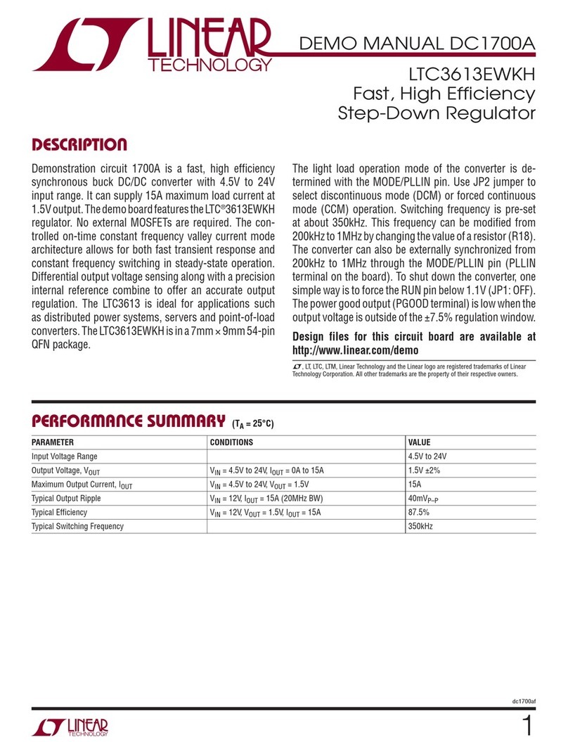
Linear Technology DC1700A Quick setup guide
Linear Technology
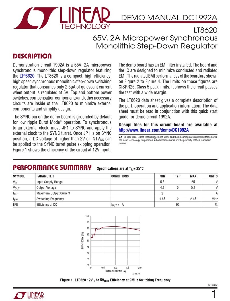
Linear Technology DC1992A Quick setup guide
Linear Technology
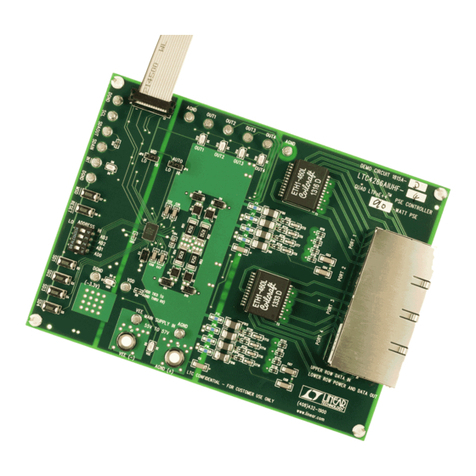
Linear Technology LTC4266A User manual
Linear Technology
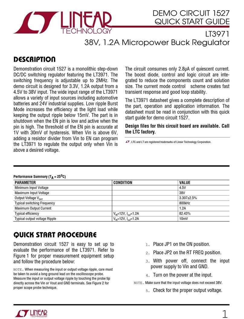
Linear Technology LT3971 User manual
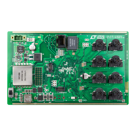
Linear Technology
Linear Technology LTC2874 Quick setup guide
Linear Technology
Linear Technology LT3790 Quick setup guide
Linear Technology
Linear Technology LT8608 User manual
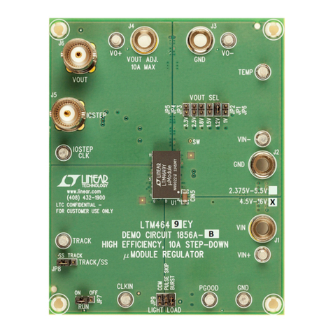
Linear Technology
Linear Technology LTM4649EY Quick setup guide

Linear Technology
Linear Technology LTC4000 User manual
Linear Technology
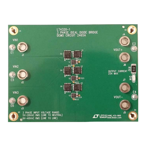
Linear Technology DC2465A Quick setup guide
Linear Technology
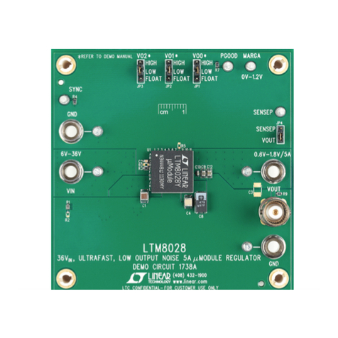
Linear Technology DC1738A Quick setup guide
Linear Technology
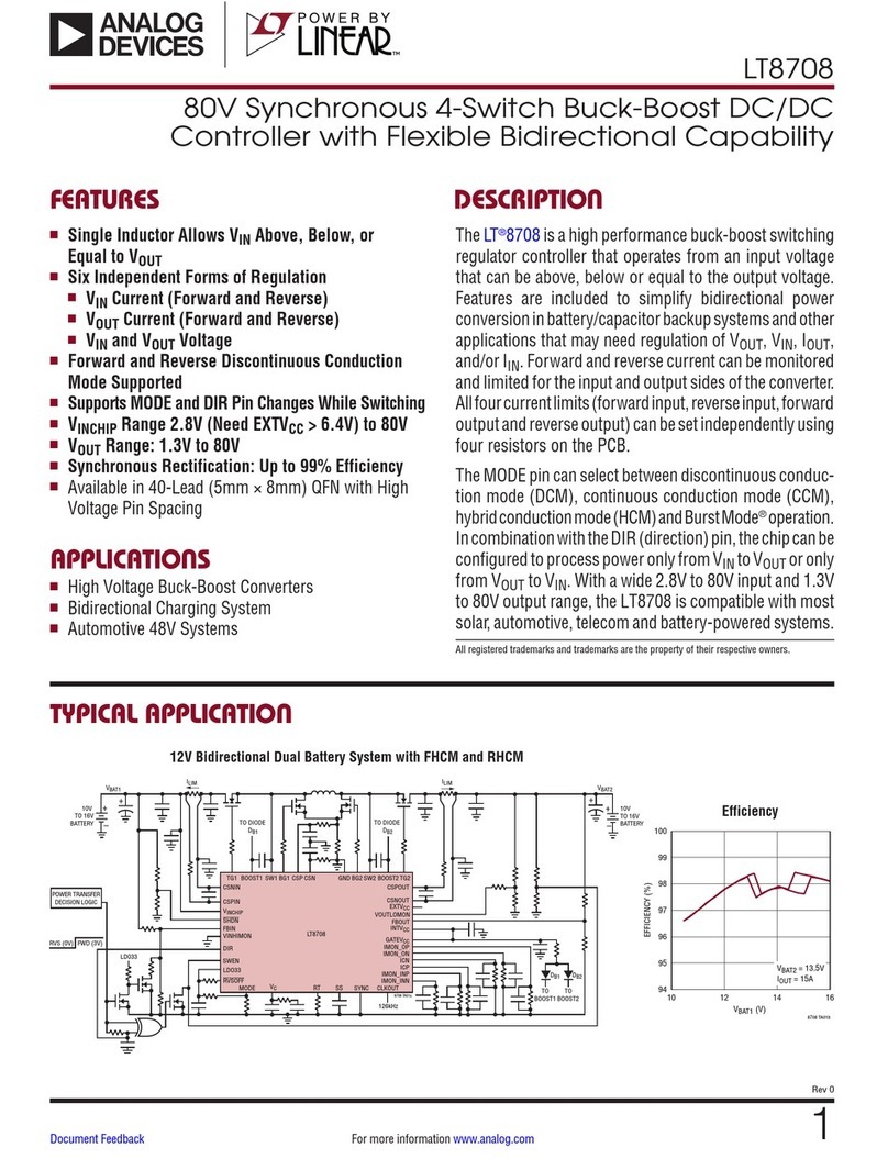
Linear Technology Analog Devices LT8708 User manual
Linear Technology
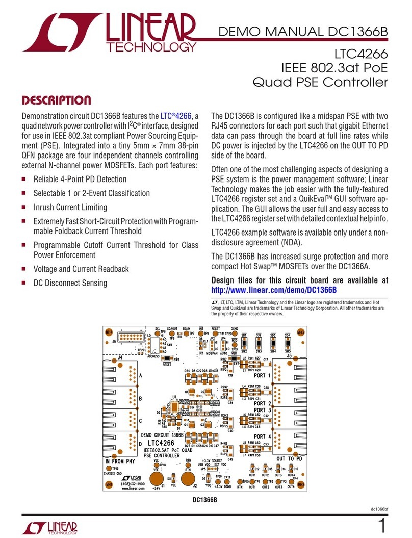
Linear Technology DC1366B User manual
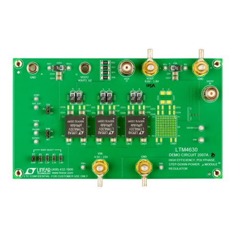
Linear Technology
Linear Technology DC2007A-B Quick setup guide
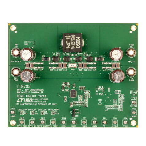
Linear Technology
Linear Technology LT8705 Quick setup guide
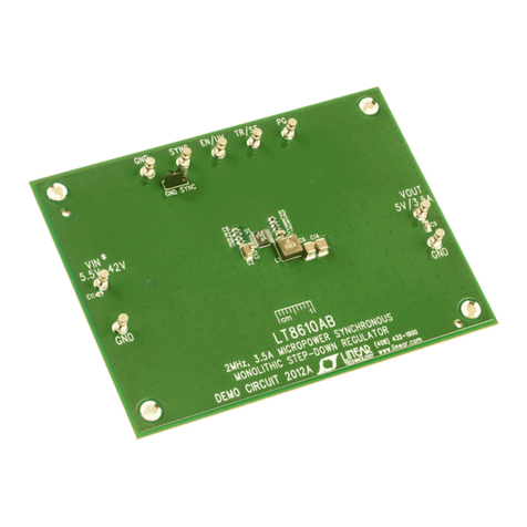
Linear Technology
Linear Technology LT8610A Quick setup guide
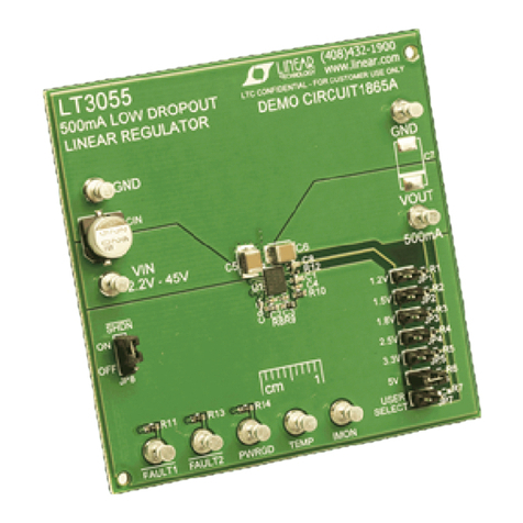
Linear Technology
Linear Technology DC1865A Quick setup guide
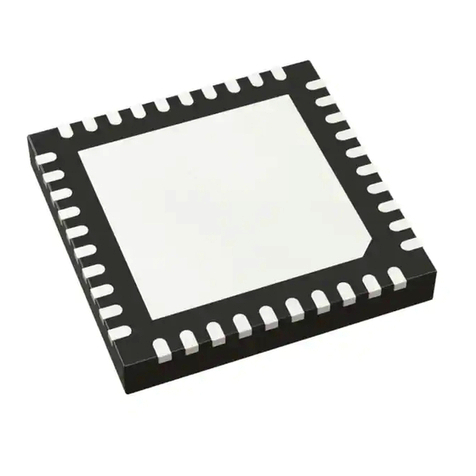
Linear Technology
Linear Technology LTC3875EUJ Quick setup guide
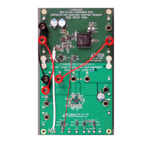
Linear Technology
Linear Technology DC1830B-C Quick setup guide
Popular Controllers manuals by other brands
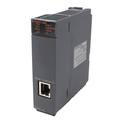
Mitsubishi
Mitsubishi MELSEC Q Series Reference manual
Watlow
Watlow Anafaze PPC-2000 user guide
Omron
Omron SYSMAC CS Series Instruction & reference manual
Tescom
Tescom 44-2800 Series Instructions for use
Nexta Tech
Nexta Tech TOUCH-1SP quick start guide

Theta Digital
Theta Digital RSC operating instructions
Intermatic
Intermatic NE 1 operating instructions
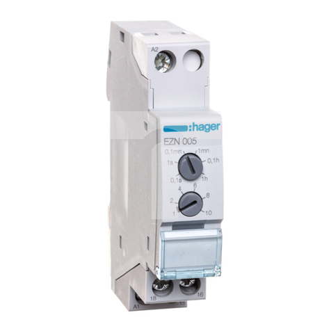
hager
hager EZN005 Instructions for use

Philadelphia Scientific
Philadelphia Scientific iBos Charger-Splitter installation manual
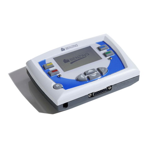
Gantner
Gantner BENZIG M1 Fancier Manual
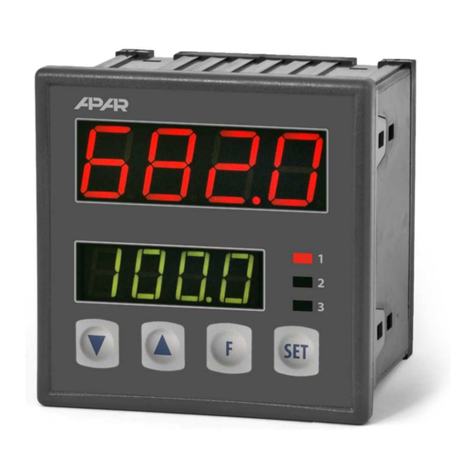
APAR
APAR AR682 user manual

Speck pumpen
Speck pumpen BADU Logic 2 Installation and operating instructions


