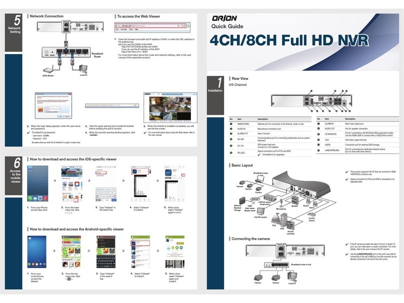
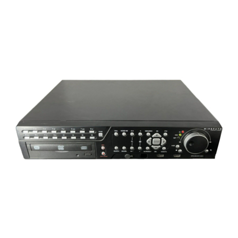
Linear QUADStor 400 series User manual

NVR 400 Series
Quick Installation Guide
USA & Canada (800) 421-1587 & (800) 392-0123
(760) 438-7000 - Toll Free FAX (800) 468-1340
www.linearcorp.com
PWR
LAN1LAN2ALM
USB1 USB2
QUADStor
™
NVR 400

ii

1
Table of Contents
1. The NVR System . . . . . . . . . . . . . . . . . . . . . . . . . . . . . . . . . . . . . . . . . . . . . . . . . . . . . . . . . . . .2
NVR Components . . . . . . . . . . . . . . . . . . . . . . . . . . . . . . . . . . . . . . . . . . . . . . . . . . . . . . . . . . . 2
2. Hard Disk (HDD) Installation . . . . . . . . . . . . . . . . . . . . . . . . . . . . . . . . . . . . . . . . . . . . . . . . . 3
Hard Disk Installation . . . . . . . . . . . . . . . . . . . . . . . . . . . . . . . . . . . . . . . . . . . . . . . . . . . . . . .3
3. NVR Hookup . . . . . . . . . . . . . . . . . . . . . . . . . . . . . . . . . . . . . . . . . . . . . . . . . . . . . . . . . . . . . . . 4
Backpanel NVR Connections. . . . . . . . . . . . . . . . . . . . . . . . . . . . . . . . . . . . . . . . . . . . . . . . . 4
Frontpanel NVR Connection . . . . . . . . . . . . . . . . . . . . . . . . . . . . . . . . . . . . . . . . . . . . . . . . . 4
4. Network Setup . . . . . . . . . . . . . . . . . . . . . . . . . . . . . . . . . . . . . . . . . . . . . . . . . . . . . . . . . . . . . 5
NVR Network Connections. . . . . . . . . . . . . . . . . . . . . . . . . . . . . . . . . . . . . . . . . . . . . . . . . . . 5
PoE vs Non-PoE Connections . . . . . . . . . . . . . . . . . . . . . . . . . . . . . . . . . . . . . . . . . . . . . . . . 5
5. System Power Up . . . . . . . . . . . . . . . . . . . . . . . . . . . . . . . . . . . . . . . . . . . . . . . . . . . . . . . . . . . 6
6. Login. . . . . . . . . . . . . . . . . . . . . . . . . . . . . . . . . . . . . . . . . . . . . . . . . . . . . . . . . . . . . . . . . . . . . . 7
7. Live Video . . . . . . . . . . . . . . . . . . . . . . . . . . . . . . . . . . . . . . . . . . . . . . . . . . . . . . . . . . . . . . . . . 8
8. Quick Setup. . . . . . . . . . . . . . . . . . . . . . . . . . . . . . . . . . . . . . . . . . . . . . . . . . . . . . . . . . . . . . . .9
9. Date and Time . . . . . . . . . . . . . . . . . . . . . . . . . . . . . . . . . . . . . . . . . . . . . . . . . . . . . . . . . . . . . 10
10. Authentication Accounts. . . . . . . . . . . . . . . . . . . . . . . . . . . . . . . . . . . . . . . . . . . . . . . . . . . 11
11. Network . . . . . . . . . . . . . . . . . . . . . . . . . . . . . . . . . . . . . . . . . . . . . . . . . . . . . . . . . . . . . . . . . 12
12. Storage. . . . . . . . . . . . . . . . . . . . . . . . . . . . . . . . . . . . . . . . . . . . . . . . . . . . . . . . . . . . . . . . . . 13
13. Adding Cameras . . . . . . . . . . . . . . . . . . . . . . . . . . . . . . . . . . . . . . . . . . . . . . . . . . . . . . . . . . 14
14. Camera Configuration . . . . . . . . . . . . . . . . . . . . . . . . . . . . . . . . . . . . . . . . . . . . . . . . . . . . . 15
15. Record Policy Cofiguration . . . . . . . . . . . . . . . . . . . . . . . . . . . . . . . . . . . . . . . . . . . . . . . . . 16
16. Stream Setup. . . . . . . . . . . . . . . . . . . . . . . . . . . . . . . . . . . . . . . . . . . . . . . . . . . . . . . . . . . . .19
17. Motion Detection . . . . . . . . . . . . . . . . . . . . . . . . . . . . . . . . . . . . . . . . . . . . . . . . . . . . . . . . .20
18. Video Playback. . . . . . . . . . . . . . . . . . . . . . . . . . . . . . . . . . . . . . . . . . . . . . . . . . . . . . . . . . . 21
19. Alarm Search . . . . . . . . . . . . . . . . . . . . . . . . . . . . . . . . . . . . . . . . . . . . . . . . . . . . . . . . . . . . 22
20. Remote App’s. . . . . . . . . . . . . . . . . . . . . . . . . . . . . . . . . . . . . . . . . . . . . . . . . . . . . . . . . . . . . 23
21. Specifications . . . . . . . . . . . . . . . . . . . . . . . . . . . . . . . . . . . . . . . . . . . . . . . . . . . . . . . . . . . . 24
22. Regulatory Information . . . . . . . . . . . . . . . . . . . . . . . . . . . . . . . . . . . . . . . . . . . . . . . . . . . . 25

2
Figure 1. System Components
NVR Components
• Thanks for choosing the
QUADStor™Network Video Recorder
(NVR). Please read this Quickstart
Guide carefully before using the NVR.
• This guide will help to perform a
Basic Setup of the Network Video
Recorder and its components.
• Follow the step-by-step instructions
and diagrams to insure proper
system functionality.
• BE SURE TO CONNECT ALL
COMPONENTS BEFORE APPLYING
POWER TO THE SYSTEM!
Here is a list of what is included:
1. QUADStor™ NVR with 2 HDD drive bays
2. Power supply
3. VGA cable Adapter
4. HDMI cable adapter
5. Power cord
6. HDDs (per configuration)
7. Setup CD
8. USB mouse
9. HDD installation screws (8)
10. NVR manual
11. NVR Quickstart Guide
1. The NVR System
QUADStor
™
NVR 400
PWR
LAN1LAN2ALM
USB2
1
7
2
4
3
5
6
10
8
9
11

3
Hard Disk Installation
Begin by installing the hard disk drive/s (HDD)
into the Network Video Recorder. It has 2 bays
to accommodate hard drives, depending on
the system configuration. Follow the steps
below.
✓NOTE: Hard drives are prone to damage from
mishandling. Be very careful not to drop them
or cause any static discharge during the
installation process.
✓NOTE: Use audio/video (AV Class), HDD’s
which are sold separately
2. Hard Disk (HDD) Installation
Figure 2. Opening NVR Bays
PUSH BUTTON/S
TO EJECT GRIP
HANDLES
1
PULL HANDLES OUTWARD
TO OPEN BAY
2
FIT HDD INTO BAY/S
1
2SECURE HDD/S IN
PLACE USING
SCREWS (PROVIDED)
PUSH IN ON HANDLE/S
UNTIL IT CLOSES INTO
HDD BAY
1
SLIDE BAY/S INTO NVR SLOT
AND APPLY FORCE UNTIL
IT “LOCKS” INTO PLACE
2
Figure 3. HDD Installation into NVR
Figure 4. Closing NVR Bays

4
Backpanel NVR Connections
Use the diagram below to properly connect
cables. Use the VGA connector/cable to install
monitor. Place switch in the VGA position. If an
HDMI monitor connector/cable is used
(optional), place switch in the HDMI
position.
3. NVR Hookup
Figure 5. NVR Backpanel Wiring Connections
Figure 6. NVR Frontpanel USB Connection
POWER CORD
TO 110V OUTLET
ETHERNET
CABLE TO
SWITCH
VGA
CONNECTOR /
CABLE TO
MONITOR
HDMI CONNECTOR /
CABLE TO MONITOR
(OPTIONAL)
HDMI VGA
HDMI VGA
PLACE SWITCH
IN CORRECT
POSITION
NETWORK VIDEO
RECORDER (NVR)
USB
PORT
LAN 1 LAN 2
QUADStor
™
NVR 400
PWR
LAN1LAN2ALM
USB2
NVR
MOUSE
USB PORT 1
Frontpanel NVR Connection
Plug mouse (provided) into NVR using USB-1
port.
✓NOTE: Mouse may also be connected to USB
port on the back of NVR.

5
NVR Network Connections
To finalize the QuickStart setup, add the
following components. Use ethernet cable for
making connections. A PC may be used to
connect system to the internet (CLOUD). A
single Network Video Recorder, with switch/
router is capable of supporting multiple IP
cameras.
✓NOTE: Figure 7 represents a Basic Working
System Configuration. To ensure that the
network will function properly, please refer
to the Operation Manuals included with each
component. When selecting monitors ONLY
USE ones with 1024 x 768 Resolution or higher
or OSD will not be displayed.
PoE vs Non-PoE Connections
Switch/Routers use Power over Ethernet (PoE)
or NON-PoE connections. PoE is a connection
which passes electrical power along with data.
Use the PoE for Ethernet cables when the
component being hooked into the system does
not have its own power supply. IP cameras are
such devices.
NVR
POWER
CLOUD
(INTERNET)
ROUTER/SWITCH
IP CAMERAS
MOUSE
NON PoE **
LAN 2
MONITOR
LAN 1
PC/BROWSER/
COMPUTER
PoE*
POWER
OPTIONAL
CONNECTION
TO ROUTER
OPTIONAL
PC/BROWSER/
COMPUTER
SMART PHONE
QUADview™
Figure 7. Network Schematic
4. Network Setup

6
Once POWER is turned on and all components
are functioning correctly, the system will go
through its initialization sequence as follows:
An audible “BEEP” will be heard from the
Network Video Recorder. Monitor screen will
display as shown: This screen display will
remain for 2 minutes while operating system
initializes. System will then go through the next
screen being a self check sequence:
5. System Power Up
NVR self-testing
cost about 2 minutes
Disk 1 1862G [OK]
Capacity 862GIG
Usable Space 1451GIG
Disk 2 [Not Existing]
Network card [OK]
HDMI&VGA [OK]
Initializing System [OK]
Figure 8. Initializing System
Figure 9. Initializing System

7
After initialization is complete, the login screen
appears as shown in Figure 10.
Change the screen resolution by clicking on the
“change” link at the bottom. Also, screen output
can be adjusted by clicking the adjust link.
Operational screen resolution is 1024 x 768 or
higher.
Place cursor in User Name block. A keyboard
will appear in the lower right corner of the
screen. Using mouse, or USB keyboard, type
“admin” in lower case letters.
Next, place cursor in Password Block and
using keyboard and mouse, retype “admin.”
Admin is the default setting used to enter
system for the first time.
Use “Login Automatically” to login upon boot-
up.
Click Login button.
QUADStor™
English
USER NAME:
PASSW O RD:
LOGIN
Login automacally
Monitor Mode is 1024X768. change
If you can’t see at four corners adjust
6. Login
Figure 10. Login Screen
IMPORTANT: Default Password is admin

8
Figure 11. Live Video Screen
Live Video is the first screen displayed
after llogging in. Figure 11 demonstrates
Live Video navigation.
1. Live Video
2. Playback
3. Alarm Search
4. Quick Setup
5. Storage Configuration
6. Backup Tasks
7. Setup (NVR, IP Cameras)
8. Layouts
9. Live View
10. Cameras List
11. Alarm Info
12. Layout (show/hide)
13. Camera (show/hide)
14. Alarm (show/hide)
15. Full Screen, Auto Full Screen
1
7. Live Video
1 2 345 6 7
8
9
10
11
12 13 14 15

9
8. Quick Setup
Figure 12. Quick Setup Screen
Select the “Quick Setup” tab to start
configuration on the QUADStor NVR.
In the NVR Setup section, set up the NVR’s
Date and Time, Accounts for IP Cameras,
Network and Storage.
In the IP Cameras section, connect IP Cameras
to the NVR using Automatic Discovery of
IP Cameras, IP Camera range, or manually
entering IP Address.

10
Figure 13. Date and Time
9. Date and Time
1. Type a device name for your NVR.
2. Click the button to the far right of the
DEVICE TIME to open date and time
window.
3. In the DATE AND TIME window, select
TIME ZONE using down arrow to the
far right.
4. Set Daylight Savings Time if desired
by selecting this option. Enter the Start
and End times for DST in your region.
5. Set Device Date and Time by editing
the pop-up menu.
6. Set Date Format as desired.
7. Click the GREEN CHECK MARK to
Save changes.
8. Use Network Time Protocol to keep
your NVR date and time accurate.
9. Type in a NTP domain name or IP
address (i.e. nist.gov) and NTP port
(i.e. Port: 123).
10. Click the GREEN CHECK MARK to
Save changes.
11. Close Date & Time window.
12. Make sure “Sync Camera Time” is set
to AUTO. The NVR Date and Time will
be synchronized to all IP Cameras

11
10. Authentication Accounts
Figure 14. Authentication Accounts
To connect the IP Cameras with the correct user
name and password, use the Authentication
Accounts section. To configure authentication
accounts and/or change passwords follow
these steps:
To add a NAME and USER PASSWORD, click
the “+” button (ADD ACCOUNT).
1. Type in User Name and Password in the
ADD ACCOUNT window and click OK.
2. To DELETE a NAME and USER
PASSWORD, click the “-” button.
WARNING: Be sure to write down in a
secure place the admin password. This
password is required to make any changes
to the NVR. To avoid unauthorized access
to your surveillance system avoid simple
passwords such as “password” or “1234”.

12
11. Network
Figure 15. Network Setup
Use the Networks section to set up Local Area
Networks (LAN1 & LAN2).
The IP Cameras can be connected to the NVR
can be a part of the main network where LAN
1 is only needed. The IP Cameras connected
to the NVR can be isolated from the main
network. In this case use LAN1 to connect the
NVR to network and LAN2 to connect the IP
Cameras on an isolated network.
To ensure recording of the IP Cameras to the
NVR, verify network connectivity. Contact your
local Network Administrator for assistance.

13
12. Storage
Figure 16. Storage Setup
The QUADStor NVR supports up to two
internal Hard Disk Drives (HDDs). Prior to
turning the NVR on, the HDD should have
been mounted to the drive bay and inserted it
into the HDD drive bay, locking it in place. If this
operation, has not been performed, insert the
HDD installed into the drive bay now. Please
wait a few seconds for the NVR to recognize it.
If the HDD is recognized, a green light next
to the storage icon will appear and the word
“USABLE” beneath it.
If this is a new HDD, you will need to format it.
To FORMAT hard drive, click FORMAT. This
will take a few minutes. WARNING: Any
information previously stored on the HDD will
be erased.
The size of the hard drive is shown in the
window next to the hard drive icon. It will
display how many GB’s have been used and
how much is left available.
If the HDD is shown as “NOT USABLE”, the
HDD is either recognized, not loaded into the
drive bay properly or it needs to be formatted.
To remove the HDD from the NVR, click the
UNLOAD button. Then the HDD may safely be
removed from the drive bay of the NVR.
Each Hard Drive can be set to the same
Disk Group or have each Hard Drive belong
to a different Disk Group. Disk Groups allow
recording an IP Camera to a specific Disk
Group (Hard Drive).

14
13. Adding Cameras
Figure 17. Adding Cameras
Use the Camera Search dialog to connect IP
Cameras to the NVR for recording.
1. To add IP Cameras, click on the SEARCH
CAMERA title as indicated above.
2. A Camera Search window will appear.
Click SCAN to discover IP cameras on the
network. Or, Manually Add IP Cameras
individually or by Network Range.
3. There should be a list of several cameras
in the window. Use the Authentication
Accounts section in this dialog if there is
the need to enter a different user name
and password. (Default User Name is
admin, Default Password is admin.)
4. The validation results should indicate a
successful connection to the camera.
5. Click the ARROW at the bottom of the
window to continue.
6. Select the cameras that are desired to be
managed by the NVR. Click the arrows in
the middle of the window to add them to
the right pane (Managed Cameras).
7. Click OK when finished.

15
14. Camera Configuration
Overview of the Camera Configuration in the
Quick Start tab:
1. ALL - allows selection of the cameras to
Delete.
2. STATUS - indicates if the IP Camera/s
are online or offline. If On-line, click on
the blue triangle icon to preview live video
from the IP camera.
3. NAME - allows ability to type in a name for
the IP Camera. This is updated in the Live
Video and Playback screens.
4. IP ADDRESS - displays IP Address of the
IP Camera. Click to edit IP Address.
5. RECORD – indicates Audio and Video
recording status. Click to edit Record
Policies including alarm events.
6. STREAM – displays current IP Camera
streaming parameters. Click to edit
Streaming parameters.
7. MOTION ALARM – displays Motion
Alarm Status. Click to setup Motion
Detection schedule and parameters for
the IP Camera
Figure 18. Camera Configuration

16
15. Record Policy Cofiguration
The Record Policy Configuration screen
configures IP Camera recording to the
QUADStor NVR.
1. Select Schedule Record. Select the
“Record Policy” to record the IP Camera
24 hours a day 7 days a week or
Schedule Recording.
a) For Schedule Recording, setup
the Schedule by clicking on the
Schedule Setting icon.
Figure 20. Schedule Recording Dialogue Box
b) Setup the Schedule in this dialog
(shown below). After changes
are made, click OK to Save the
changes.
Figure 19. Record Policy Configuration

17
Record Policy Configuration (Cont.)
2. Select Alarm Record to enable to the IP
Camera to record on Alarms or Motion.
a) The “Pre-Record” option allows the IP
Camera to Record to the NVR before the
Alarm event occurs.
b) Define a “Post-Record” time to determine
how many seconds of recording after the
Alarm event has occurred.
c) Select I/O Alarm to record on an alarm
contact.
d) Select Motion Alarm to record on a
Motion Event. To setup the NVR to
record on Motion, setup the Motion Alarm
parameters in the Quick Setup menu and
disable Schedule Record.
Figure 21. Record Policy Configuration

18
Record Policy Configuration (Cont.)
3. Select “Record Audio” to record IP
Camera audio.
4. Set the “Storage Policy” to Overwrite the
video recording when the disk is full, or
save recording of a set number of days.
After the set number days, the recording
will not be accessible.
5. Set “Disk Group” to designate the disk
group the IP Camera will record to.
6. “Stream” specifies which IP Camera
stream will be recording to the NVR.
Figure 22. Storage Policy
Table of contents
