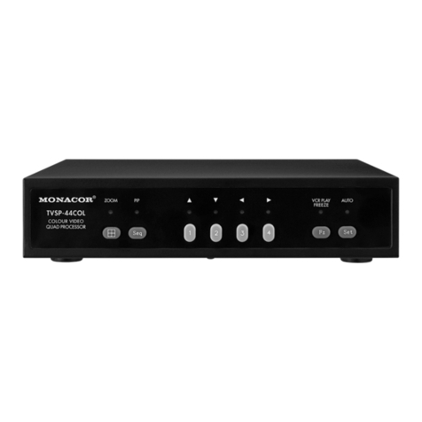
Monacor DMR-425A User manual

BEDIENUNGSANLEITUNG
INSTRUCTION MANUAL
MODE D’EMPLOI
ISTRUZIONI PER L’USO
VEILIGHEIDSVOORSCHRIFTEN
CONSEJOS DE SEGURIDAD
ŚRODKI BEZPIECZEŃSTWA
SIKKERHEDSOPLYSNINGER
SÄKERHETSFÖRESKRIFTER
TURVALLISUUDESTA
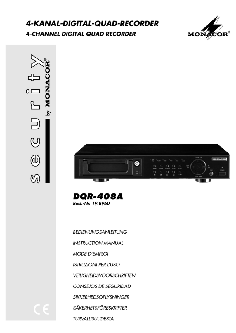
4-KANAL-DIGITAL-MULTIPLEXRECORDER
4-CHANNEL DIGITAL MULTIPLEX RECORDER
DMR-425A
Best.-Nr. 19.9870
®

2
Bevor Sie einschalten ...
Wir wünschen Ihnen viel Spaß mit Ihrem neuen Gerät
von MONACOR. Dabei soll Ihnen diese Bedienungsan-
leitung helfen alle Funktionsmöglichkeiten kennen zu
lernen. Die Beachtung der Anleitung vermeidet außer-
dem Fehlbedienungen und schützt Sie und Ihr Gerät vor
eventuellen Schäden durch unsachgemäßen Gebrauch.
Den deutschen Text finden Sie auf den Seiten 4–25.
Before you switch on ... ...
We wish you much pleasure with your new unit by
MONACOR. With these operating instructions you will
be able to get to know all functions of the unit. By follow-
ing these instructions false operations will be avoided,
and possible damage to you and your unit due to improp-
er use will be prevented.
You will find the English text on the pages 4–25.
D
A
CH
GB
Avant toute mise en service ...
Nous vous remercions d’avoir choisi un appareil
MONACOR et vous souhaitons beaucoup de plaisir à
l’utiliser. Cette notice a pour objectif de vous aider à
mieux connaître les multiples facettes de l’appareil et à
vous éviter toute mauvaise manipulation.
La version française se trouve pages 26–47.
Prima di accendere ...
Vi auguriamo buon divertimento con il Vostro nuovo ap-
parecchio MONACOR. Le istruzioni per l’uso Vi possono
aiutare a conoscere tutte le possibili funzioni. E
rispettando quanto spiegato nelle istruzioni, evitate di
commettere degli errori, e così proteggete Voi stessi, ma
anche l’apparecchio, da eventuali rischi per uso improprio.
Il testo italiano lo potete trovare alle pagine 26–47.
F
B
CH
I
Voordat u inschakelt ...
Wij wensen u veel plezier met uw nieuw toestel van
MONACOR. Lees de veiligheidsvoorschriften, alvorens
het toestel in gebruik te nemen. Door de veiligheidsvoor-
schriften op te volgen zal een slechte werking vermeden
worden, en zal een eventueel letsel aan uzelf en schade
aan uw toestel tengevolge van onzorgvuldig gebruik
worden voorkomen.
U vindt de veiligheidsvoorschriften op pagina 48.
Antes de cualquier instalación ...
Tenemos de agradecerle el haber adquirido un aparato
MONACOR y le deseamos un agradable uso. Por favor
lee las instrucciones de seguridad antes del uso. La
observación de las instrucciones de seguridad evita ope-
raciones erróneas y protege Vd. y vuestro aparato con-
tra todo daño posible por cualquier uso inadecuado.
Las instrucciones de seguridad se encuentran en la
página 48.
NL
B
E
Przed Uruchomieniem …
Życzymy zadowolenia z nowego produktu MONACOR.
Przed użyciem proszę przeczyta środki bezpieczeń-
stwa. Uniknie się w ten sposób błędów obsługi oraz
uszkodzenia sprzętu w wyniku nieodpowiedniego
użytkowania.
Środki bezpieczeństwa znajdują się na stronie 48.
Inden De tænder for apparatet ...
Vi ønsker Dem god fornøjelse med Deres nye MONA-
COR apparat. Læs oplysningerne for en sikker brug af
apparatet før ibrugtagning. Følg sikkerhedsoplysnin-
gerne for at undgå forkert betjening og for at beskytte
Dem og Deres apparat mod skade på grund af forkert
brug.
Sikkerhedsoplysningerne finder De på side 49.
PL DK
Förskrift
Vi önskar dig mycket nöje med din nya enhet från
MONACOR. Läs gärna säkerhetsinstruktionerna innan
du använder enheten. Genom att följa säkerhetsinstruk-
tionerna kan många problem undvikas, vilket annars kan
skada enheten.
Du finner säkerhetsinstruktionerna på sidan 49.
SEnnen virran kytkemistä…
Toivomme, että uusi MONACOR-laitteesi tuo sinulle pal-
jon iloa ja hyötyä. Ole hyvä ja lue käyttöohjeet ennen lait-
teen käyttöönottoa. Luettuasi käyttöohjeet voit käyttää
laitetta turvallisesti ja vältyt laitteen väärinkäytöltä.
Käyttöohjeet löydät sivulta 49.
FIN

VIDEO
EXTERNAL I/O
AUDIO
IN OUT
1
2
3
4
123 4
IN
IN
OUT
DC 19V
CALL
MAIN
Main Monitor
POWER
H-HOLD V-HOLD BRIGHT CONTRAST
Alarm Device Alarm
Sensor 1 Alarm
Sensor 2 Alarm
Sensor 3 Alarm
Sensor 4
Video Server Computer
Call Monitor
®
POWER
O
I
H-HOLD V-HOLD BRIGHT CONTRAST
Camera 1
Camera 2
Camera 3
Camera 4
Camera 1
Camera 2
CCD CAMERA
Camera 3
CCD CAMERA
Camera 4
CCD CAMERA
CCD CAMERA
AUDIO OUT
AUDIO OUT
VIDEO OUT
CALL
AUDIO IN 1
AUDIO IN 2
AUDIO IN 3
AUDIO IN 4
VIDEO IN 1
VIDEO IN 2
VIDEO IN 3
VIDEO IN 4
VIDEO OUT
MAIN
REMOTE
CONTROL
REMOTE
CONTROL
4 x ALARM IN
ALARM OUT
VIDEO
EXTERNAL I/O
AUDIO
IN OUT
1
2
3
4
12 3 4
MAIN
IN
IN
OUT
DC 19V
CALL
3
Digital Video Recorder
12
34
REC PLAY PAUSE STOP REW FF
HDD HDD Full ALARM TIMER PLAY REC MENU ENTER SEARCH ZOOM SLOW
123456 7
1
2
3
8 9 10 11 12 13 14 15 16 17 18 19 20
21 22 23 24 25 26 27

1 Übersicht der Bedienelemente und
Anschlüsse . . . . . . . . . . . . . . . . . . . . . . . . . 5
2 Hinweise für den sicheren Gebrauch . . . . 6
3 Anwendungsmöglichkeiten . . . . . . . . . . . . 6
4 Geräte anschließen . . . . . . . . . . . . . . . . . . 7
4.1 Videoanschlüsse . . . . . . . . . . . . . . . . . . . . . 7
4.2 Audioanschlüsse . . . . . . . . . . . . . . . . . . . . . 7
4.3 Alarm- und Steueranschlüsse . . . . . . . . . . . 7
4.3.1 Alarmeingänge . . . . . . . . . . . . . . . . . . . . . . 7
4.3.2 Alarmausgang . . . . . . . . . . . . . . . . . . . . . . 7
4.3.3 Eingang zur Alarmzurücksetzung . . . . . . . . 7
4.3.4 Steuerausgang „Festplatte voll“ . . . . . . . . . 7
4.3.5 Fernsteuerung . . . . . . . . . . . . . . . . . . . . . . 7
5 Inbetriebnahme . . . . . . . . . . . . . . . . . . . . . . 8
5.1 Umschaltung PAL/NTSC . . . . . . . . . . . . . . . 8
5.2 Bedientasten sperren . . . . . . . . . . . . . . . . . . 8
6 Live-Überwachung . . . . . . . . . . . . . . . . . . . 9
6.1 Anzeigeformate wählen . . . . . . . . . . . . . . . . 9
6.1.1 Vollbild-Format . . . . . . . . . . . . . . . . . . . . . . 9
6.1.2 Mehrfachbild-Formate . . . . . . . . . . . . . . . . 9
6.1.3 Zoom-Funktion . . . . . . . . . . . . . . . . . . . . . . 9
7 Aufnahme . . . . . . . . . . . . . . . . . . . . . . . . . . 9
7.1 Manuell gestartete Aufnahme . . . . . . . . . . 10
7.2 Timergesteuerte Aufnahme . . . . . . . . . . . . 10
7.3 Aufnahmestart bei externem Alarm . . . . . . 10
7.4 Aufnahmestart durch den internen
Video-Bewegungsdetektor . . . . . . . . . . . . . 10
8 Wiedergabe . . . . . . . . . . . . . . . . . . . . . . . . 10
8.1 Schneller Vor-/Rücklauf . . . . . . . . . . . . . . . 11
8.2 Langsamer Vor-/Rücklauf . . . . . . . . . . . . . 11
8.3 Schrittweise Wiedergabe von
Einzelbildern im Pausenmodus . . . . . . . . . 11
8.4 Bestimmte Aufnahme suchen
und abspielen . . . . . . . . . . . . . . . . . . . . . . . 11
8.4.1 LAST RECORD:
Wiedergabe der letzten Aufnahme . . . . . . 11
8.4.2 FULL LIST:
Gesamtliste aller Aufnahmen . . . . . . . . . . 11
8.4.3 ALARM LIST:
Liste der durch einen externen Alarm
ausgelösten Aufnahmen . . . . . . . . . . . . . . 12
8.4.4 MOTION LIST:
Liste der detektorgestarteten Aufnahmen . 12
8.4.5 TIME SEARCH:
Aufnahmesuche über Zeit-/
Datumsangabe . . . . . . . . . . . . . . . . . . . . .12
9 Änderung der Betriebsparameter . . . . . . 13
9.1 Hauptmenü . . . . . . . . . . . . . . . . . . . . . . . . . 13
9.2 Menü TIMER . . . . . . . . . . . . . . . . . . . . . . . 13
9.3 Menü CAMERA . . . . . . . . . . . . . . . . . . . . . 15
9.4 Menü RECORD . . . . . . . . . . . . . . . . . . . . . 15
9.5 Menü ALARM . . . . . . . . . . . . . . . . . . . . . . . 15
9.6 Menü DWELL . . . . . . . . . . . . . . . . . . . . . . . 16
9.7 Menü PIP . . . . . . . . . . . . . . . . . . . . . . . . . . 16
9.8 Menü MOTION . . . . . . . . . . . . . . . . . . . . . . 17
9.9 Menü DISPLAY . . . . . . . . . . . . . . . . . . . . . 18
9.10 Menü REMOTE . . . . . . . . . . . . . . . . . . . . . 18
9.11 Menü USER . . . . . . . . . . . . . . . . . . . . . . . . 18
9.12 Menü SYSTEM . . . . . . . . . . . . . . . . . . . . . 19
9.13 Menü EVENT . . . . . . . . . . . . . . . . . . . . . . . 20
10 Alarmfunktionen . . . . . . . . . . . . . . . . . . . . 21
10.1 Externer Alarm . . . . . . . . . . . . . . . . . . . . . . 21
10.2 Alarm bei Ausfall eines Videosignals . . . . . 21
10.3 Alarm vom internen Bewegungsdetektor . 21
10.4 Alarm vorzeitig ausschalten . . . . . . . . . . . . 21
11 Befehlsübersicht für die
Computer-Schnittstelle . . . . . . . . . . . . . . 22
12 Festplatte auswechseln . . . . . . . . . . . . . . 23
12.1 Festplatte herausnehmen . . . . . . . . . . . . . 23
12.2 Neue Festplatte einsetzen . . . . . . . . . . . . . 23
13 Technische Daten . . . . . . . . . . . . . . . . . . . 23
13.1 Aufnahmekapazität . . . . . . . . . . . . . . . . . . 24
13.2 Kompatible Festplatten . . . . . . . . . . . . . . . 25
1 Operating Elements and Connections . . . 5
2 Safety Notes . . . . . . . . . . . . . . . . . . . . . . . . 6
3 Applications . . . . . . . . . . . . . . . . . . . . . . . . 6
4 Connecting the Units . . . . . . . . . . . . . . . . . 7
4.1 Video connections . . . . . . . . . . . . . . . . . . . . 7
4.2 Audio connections . . . . . . . . . . . . . . . . . . . . 7
4.3 Alarm and control connections . . . . . . . . . . . 7
4.3.1 Alarm inputs . . . . . . . . . . . . . . . . . . . . . . . . 7
4.3.2 Alarm output . . . . . . . . . . . . . . . . . . . . . . . . 7
4.3.3 Input for alarm reset . . . . . . . . . . . . . . . . . . 7
4.3.4 Control output “Disk Full” . . . . . . . . . . . . . . 7
4.3.5 Remote control . . . . . . . . . . . . . . . . . . . . . . 7
5 Setting the Unit into Operation . . . . . . . . . 8
5.1 Selection PAL/NTSC . . . . . . . . . . . . . . . . . . 8
5.2 Locking of control keys . . . . . . . . . . . . . . . . . 8
6 Live Surveillance . . . . . . . . . . . . . . . . . . . . 9
6.1 Selecting display formats . . . . . . . . . . . . . . . 9
6.1.1 Full screen format . . . . . . . . . . . . . . . . . . . . 9
6.1.2 Multiple picture formats . . . . . . . . . . . . . . . 9
6.1.3 Zoom function . . . . . . . . . . . . . . . . . . . . . . . 9
7 Recording . . . . . . . . . . . . . . . . . . . . . . . . . . 9
7.1 Manual recording . . . . . . . . . . . . . . . . . . . . 10
7.2 Timer-controlled recording . . . . . . . . . . . . . 10
7.3 Recording start in case of external alarm . . 10
7.4 Recording start by the internal
video motion detector . . . . . . . . . . . . . . . . . 10
8 Replay . . . . . . . . . . . . . . . . . . . . . . . . . . . . 10
8.1 Fast forward/rewind . . . . . . . . . . . . . . . . . . 11
8.2 Slow forward/rewind . . . . . . . . . . . . . . . . . . 11
8.3 Stepwise replay of individual pictures
in the pause mode . . . . . . . . . . . . . . . . . . . 11
8.4 Searching and replaying
a certain recording . . . . . . . . . . . . . . . . . . . 11
8.4.1 LAST RECORD:
Replaying the last recording . . . . . . . . . . . 11
8.4.2 FULL LIST:
Total list of all recordings . . . . . . . . . . . . . 11
8.4.3 ALARM LIST:
List of the recordings triggered
by an external alarm . . . . . . . . . . . . . . . . . 12
8.4.4 MOTION LIST:
List of the recordings triggered
by the detector . . . . . . . . . . . . . . . . . . . . . 12
8.4.5 TIME SEARCH:
Searching a recording via
the time/date indication . . . . . . . . . . . . . . 12
9 Modification of the
Operating Parameters . . . . . . . . . . . . . . . 13
9.1 Main menu . . . . . . . . . . . . . . . . . . . . . . . . . 13
9.2 Menu TIMER . . . . . . . . . . . . . . . . . . . . . . . 13
9.3 Menu CAMERA . . . . . . . . . . . . . . . . . . . . . 15
9.4 Menu RECORD . . . . . . . . . . . . . . . . . . . . . 15
9.5 Menu ALARM . . . . . . . . . . . . . . . . . . . . . . . 15
9.6 Menu DWELL . . . . . . . . . . . . . . . . . . . . . . . 16
9.7 Menu PIP . . . . . . . . . . . . . . . . . . . . . . . . . . 16
9.8 Menu MOTION . . . . . . . . . . . . . . . . . . . . . . 17
9.9 Menu DISPLAY . . . . . . . . . . . . . . . . . . . . . 18
9.10 Menu REMOTE . . . . . . . . . . . . . . . . . . . . . 18
9.11 Menu USER . . . . . . . . . . . . . . . . . . . . . . . . 18
9.12 Menu SYSTEM . . . . . . . . . . . . . . . . . . . . . 19
9.13 Menu EVENT . . . . . . . . . . . . . . . . . . . . . . . 20
10 Alarm Functions . . . . . . . . . . . . . . . . . . . . 21
10.1 External alarm . . . . . . . . . . . . . . . . . . . . . . 21
10.2 Alarm in case of video signal loss . . . . . . . 21
10.3 Alarm by the internal motion detector . . . . . 21
10.4 Switching off the alarm at any time . . . . . . 21
11 List of Commands for the
Computer Interface . . . . . . . . . . . . . . . . . 22
12 Replacing the Hard Disk . . . . . . . . . . . . . 23
12.1 Removing the hard disk . . . . . . . . . . . . . . 23
12.2 Inserting a new hard disk . . . . . . . . . . . . . . 23
13 Specifications . . . . . . . . . . . . . . . . . . . . . . 23
13.1 Recording capacity . . . . . . . . . . . . . . . . . . . 24
13.2 Compatible hard disks . . . . . . . . . . . . . . . . 25
4
GB
D
A
CH
Inhalt
Contents

Bitte klappen Sie die Seite 3 heraus. Sie sehen
dann immer die beschriebenen Bedienelemente
und Anschlüsse.
1 Übersicht der Bedienelemente und
Anschlüsse
1Zifferntasten 1 bis 4 zur Wahl eines Kamera-
kanals für die Ansicht im Vollbild-Format
2Taste REC zum manuellen Starten einer Auf-
nahme
3Taste PLAY zum Starten der Wiedergabe
4Taste PAUSE ( ): dient
a als Pausentaste im Wiedergabebetrieb
b alsCursor-Taste„aufwärts“ auf den Menüseiten
5Taste STOP ( ): dient
a als Stopptaste während der Aufnahme und
der Wiedergabe
b als Cursor-Taste „abwärts“ auf den Menüseiten
6Taste REW ( ): dient
a für den schnellen und langsamen Bild-Rück-
lauf im Wiedergabebetrieb
b als Cursor-Taste „links“ auf den Menüseiten
7Taste FF ( ): dient
a für den schnellen und langsamen Bild-Vorlauf
im Wiedergabebetrieb
b als Cursor-Taste „rechts“ auf den Menüseiten
8Festplatteneinschub; zumHerausnehmen des
Einschubs muss dieser über das Schloss (9)
entriegelt werden (siehe Abb. 7 in Kapitel 12)
9Schloss zum Verriegeln/Entriegeln des Festplat-
eneinschubs (8) mit den zwei beiliegenden
Schlüsseln, siehe auch Abb. 7 in Kapitel 12
10 Abdeckklappe für das Schloss (9)
11 LED-Statusanzeigen
HDD: leuchtet bei Zugriff auf die Festplatte
HDDFull: leuchtet, wenn die Speicherkapazität
der Festplatte erschöpft ist
ALARM: leuchtet, wenn die Funktion „externer
Alarm“ aktiviert ist (siehe Kap. 9.5,
Einstellung ALARM ENABLE im
Menü ALARM)
TIMER: leuchtet bei eingeschalteter Timer-
Funktion (siehe Kap. 9.2, Einstellung
TIMER ENABLE im Menü TIMER)
PLAY: leuchtet während der Wiedergabe
REC: leuchtet während der Aufnahme
12 Taste MENU dient
a zum Aufrufen des Einstellmenüs und Verlas-
sen der Menüseiten; beim Verlassen des
Hauptmenüs mit der Taste werden alle geän-
derten Einstellungen gespeichert
b in Kombination mit der Taste ENTER (13) zum
Sperren und Entsperren der Bedientasten;
zum Entsperren muss zusätzlich ein Passwort
eingegeben werden (siehe Kap. 5.2)
13 Taste ENTER dient
a im Einstellmenü zum Aufrufen der Menüseiten
und zum Aktivieren bestimmter Menü-Optio-
nen
b im Suchmenü zum Aufrufen von angewählten
Aufnahmen
14 Taste SEARCH zum Aufrufen des Suchmenüs
für die gezielte Suche einer Aufnahme
15 Taste ZOOM zum Ein-/Ausschalten der Zoom-
Funktion (siehe Kap. 6.1.3)
16 Taste /+: dient
a zum Aufrufen des Bild-im-Bild-Formats (Ein-
blendung eines kleinen Bildes in ein Vollbild)
b im Einstellmenü zum Ändern der Einstellungen
17 Taste /
-
: dient
a zum Aufrufen der beiden Vierfachbild-Formate
(1. Tastendruck) und (2. Tastendruck)
b im Einstellmenü zum Ändern der Einstellungen
18 Taste SLOW zum Reduzieren der Wiedergabe-
geschwindigkeit
19 Ein-/Ausschalter
20 Betriebsanzeige
rot: Standby-Betrieb; der Recorder ist an die
Stromversorgung angeschlossen, aber
noch ausgeschaltet
orange: während der Initialisierung des Recor-
ders nach dem Einschalten
grün: der Recorder ist eingeschaltet und be-
triebsbereit
21 15-polige Sub-D-Buchse EXTERNALI/O für ver-
schiedene Alarm- und Steuerverbindungen;
Details siehe Kap. 4.3
➃Sub-D-Buchse (Ansicht der Buchsenseite)
Pin 1: RS-232-Schnittstelle: TX
Pin 2: RS-232-Schnittstelle: RX
Pin 3: Alarm-Eingang 1
Pin 4: Alarm-Eingang 2
Pin 5: Alarm-Eingang 3
Pin 6: Alarm-Eingang 4
Pin 7: Alarmausgang: NC-Kontakt („normally
closed“) des Relais
Pin 8: Alarmausgang: NO-Kontakt („normally
open“) des Relais
Pin 9: Masse
Pin 10: RS-485-Schnittstelle: B
Pin 11: RS-485-Schnittstelle: A
Pin 12: Steuerausgang zum Starten eines zwei-
ten Digitalrecorders, wenn die Speicher-
kapazität der Festplatte erschöpft ist
Pin 13: Eingang zurAlarmzurücksetzung
Pin 14: nicht belegt
Pin 15: Alarmausgang: gemeinsamerAnschluss
(COM) des Relais
22 BNC-Eingangsbuchsen 1–4 zum Anschluss an
die Videoausgänge der Kameras
1
9
8
15
Please unfold page 3. Then you can always see
the operating elements and connections de-
scribed.
1 Operating Elements and Connections
1Numerical keys 1 to 4 for selecting a camera
channel for display in full screen format
2Key REC for manual start of a recording
3Key PLAY for starting the replay
4Key PAUSE ( ): serves
a as a pause key in the replay mode
b as a cursor key “Up” on the menu pages
5Key STOP ( ): serves
a as a stop key during the recording and the
replay
b as a cursor key “Down” on the menu pages
6Key REW ( ): serves
a for the fast and slow rewind of pictures in the
replay mode
b as a cursor key “Left” on the menu pages
7Key FF ( ): serves
a for the fast and slow forward of pictures in the
replay mode
b as a cursor key “Right” on the menu pages
8Harddisk insertion; to remove the insertion, it must
be unlocked via its lock (9) [see fig. 7 in chap. 12]
9Lock for locking/unlocking the hard disk insertion
(8) with the two keys supplied, also see fig. 7 in
chapter 12
10 Cover plate for the lock (9)
11 LED status indications
HDD: lightsup duringaccess to the hard disk
HDD Full: lights up if the storage capacity of the
hard disk is exhausted
ALARM: lights up if the function “external
alarm” has been activated (see chap-
ter 9.5, setting ALARM ENABLE in
the menu ALARM)
TIMER: lights up with activated timer function
[see chapter 9.2, setting TIMER EN-
ABLE in the menu TIMER]
PLAY: lights up during the replay
REC: lights up during the recording
12 Key MENU serves
a for calling the adjusting menu and for exiting the
menu pages; when exiting the main menu with
this key, all modified settings will be memorized
b in combination with the key ENTER (13) for
locking and unlocking the control keys; for
unlocking, a password must be entered in
addition (see chapter 5.2)
13 Key ENTER serves
a in the adjusting menu for calling the menu
pages and for activating certain menu options
b in the search menu for calling selected record-
ings
14 Key SEARCH for calling the search menu for the
purposeful search of a recording
15 Key ZOOM to activate/deactivate the zoom fun-
ction (see chapter 6.1.3)
16 Key /+: serves
a for calling the picture-in-picture format (inser-
tion of a small picture inside a full screen pic-
ture)
b in the adjusting menu for changing the settings
17 Key /
-
: serves
a for calling the two 4-channel display formats
(first actuation of key) and (second
actuation of key)
b in the adjusting menu for changing the settings
18 Key SLOW for reducing the replay speed
19 Power switch
20 Power LED
red: stand-by mode; the recorder is connect-
ed to the power supply but still switched
off
orange: during the initialization of the recorder
after switching on
green: the recorder is switched on and ready
for operation
21 15-pole Sub-D jack EXTERNAL I/O for various
alarm and control connections; details see chap-
ter 4.3
➃Sub-D jack (view of the jack side)
pin 1: RS-232 interface: TX
pin 2: RS-232 interface: RX
pin 3: alarm input 1
pin 4: alarm input 2
pin 5: alarm input 3
pin 6: alarm input 4
pin 7: alarm output: NC (normally closed)
contact of the relay
pin 8: alarm output: NO (normally open)
contact of the relay
pin 9: ground
pin 10: RS-485 interface: B
pin 11: RS-485 interface: A
pin 12: control output for starting a second dig-
ital recorder if the storage capacity of
the hard disk is exhausted
pin 13: input for alarm reset
pin 14: not connected
pin 15: alarm output: common connection
(COM) of the relay
22 BNC input jacks 1 to 4 for connection to the video
outputs of the cameras
23 BNC output jack CALL for connection to the
video input of an auxiliary monitor; the auxiliary
monitor shows the camera pictures in the full
screen format with automatic sequential switch-
ing of pictures
1
9
8
15
5
GB
D
A
CH

23 BNC-Ausgangsbuchse CALL zum Anschluss an
den Videoeingang eines Nebenmonitors; der
Nebenmonitor zeigt die Kamerabilder im Vollbild-
Format mit automatischer Bildweiterschaltung
24 BNC-Ausgangsbuchse MAIN zum Anschluss an
den Videoeingang des Hauptmonitors; über den
Hauptmonitor ist es möglich, die Kamerabilder in
verschiedenen Bildformaten anzuzeigen und das
Bildschirm-Menü aufzurufen
25 Audioeingänge 1–4 (Cinch-Buchsen) zum An-
schluss von vier Audioquellen (z.B. Audioaus-
gänge der verwendeten Kameras oder Mikrofon-
vorverstärker von separat aufgestellten Mikro-
fonen)
Hinweis: Es kann nur einer der vierAudiokanäle
aufgezeichnet werden; den Audiokanal
im Menü SYSTEM (Kap. 9.12) aus-
wählen.
26 Audioausgänge (Cinch-Buchsen) zumAnschluss
an den Audioeingang eines Monitors oder an
einen Line-Pegel-Eingang einer Audioanlage; an
beiden Ausgängen liegt das Signal des für die
Aufnahme ausgewählten Audiokanals an
27 Stromversorgungsbuchse DC 19V für den An-
schluss des beiliegenden Netzgerätes
2 Hinweise für den sicheren Gebrauch
Der Recorder und sein Netzgerät entsprechen der
EMV-Richtlinie für elektromagnetische Verträglich-
keit 89/336/EWG. Das Netzgerät entspricht zusätz-
lich der Niederspannungsrichtlinie 73/23/EWG.
Beachten Sie auch unbedingt folgende Punkte:
●Der Recorder und das Netzgerät sind nur zur Ver-
wendung im Innenbereich geeignet. Schützen Sie
die Geräte vor Tropf- und Spritzwasser, hoher
Luftfeuchtigkeit und Hitze (zulässiger Einsatztem-
peraturbereich 10–40°C).
●Stellen Sie keine mit Flüssigkeit gefüllten Gefäße,
z.B. Trinkgläser oder Vasen, auf die Geräte.
●Die im Recorder entstehende Wärme muss durch
Luftzirkulation abgegeben werden. Darum dürfen
die Lüftungsschlitze am Gehäuse nicht abgedeckt
werden.
●Stecken Sie nichts durch die Lüftungsschlitze!
Dies kann zu einem Defekt des Gerätes führen.
●Nehmen Sie den Recorder nicht in Betrieb bzw.
ziehen Sie den Netzstecker des Netzgerätes
sofort aus der Steckdose, wenn:
1. sichtbare Schäden am Netzgerät, an dessen
Netzleitung oder am Recorder vorhanden sind,
2. nach einem Sturz oder Ähnlichem der Verdacht
auf einen Defekt besteht,
3. Funktionsstörungen auftreten.
Lassen Sie die Geräte in jedem Fall in einer Fach-
werkstatt reparieren.
●Ziehen Sie den Netzstecker des Netzgerätes nie
an der Zuleitung aus der Steckdose, fassen Sie
immer am Stecker an.
●Verwenden Sie zum Reinigen nur ein trockenes
weiches Tuch, niemals Chemikalien oder Wasser.
●Wird der Recorder oder das Netzgerät zweckent-
fremdet, falsch angeschlossen bzw. bedient oder
nicht fachgerecht repariert, kann keine Haftung für
daraus resultierende Sach- oder Personenschä-
den und keine Garantie für das Gerät übernom-
men werden.
3 Anwendungsmöglichkeiten
Der DMR-425A ist ein digitaler 4-Kanal-Multiplex-
recorder und speziell für den Einsatz in Video-Über-
wachungsanlagen konzipiert. Das Gerät ist mit einer
auswechselbaren 160-GB-Festplatte ausgestattet.
Bei eingeschaltetem Überschreibmodus ist ein End-
losbetrieb möglich.
Der Recorder bietet u.a. folgende Funktionen:
– Aufzeichnung von 4 Kameras wahlweise im
Multiplex- oder Quad-Modus
– 4Aufnahmequalitäten (Basic, Normal, High, Best)
und 6Aufnahmegeschwindigkeiten [1, 2, 3, 6, 12,
25 Bilder/s (PAL) bzw. 1, 2, 4, 8, 15, 30 Bilder/s
(NTSC)] einstellbar
– Audioaufzeichnung für einen Kanal möglich
– 4Aufnahmearten (manuell gestartete, timerge-
steuerte, durch ein externes Alarmsignal oder
durch den internen Bewegungsdetektor ausge-
löste Aufzeichnung)
– Video-Bewegungsdetektor für jeden Kameraka-
nal unterschiedlich einstellbar
– schnelle Suche einerAufnahme über Zeitangabe
– schneller und langsamer Vor-/Rücklauf mit je-
weils 5 wählbaren Geschwindigkeiten
– Live-Überwachung auf dem Hauptmonitor in ver-
schiedenenAnzeigeformaten ohne Beeinflussung
einer Aufnahme: Vollbild, Vierfachbild, Bild-im-
Bild, Digital-Zoom (max. 4fache Vergrößerung)
– Live-Überwachung auf einem zweiten Monitor
mit automatischer Bildweiterschaltung möglich
– Passwortschutz und Bediensperre
– Ereignisse, wie z.B. Ausfall eines Videosignals
oder Stromunterbrechung, werden in einer Liste
protokolliert
– 4 Alarmeingänge, 1 Alarmausgang, 1 Alarm-
Reset-Eingang
– umschaltbar PAL/NTSC
– RS-232- und RS-485-Schnittstelle zur Fernsteue-
rung des Gerätes über Computer oder Terminal
Sollen die Geräte endgültig aus dem
Betrieb genommen werden, übergeben
Sie sie zur umweltgerechten Entsorgung
einem örtlichen Recyclingbetrieb.
Achtung! Das Netzgerät wird mit lebensgefähr-
licher Netzspannung versorgt. Nehmen Sie des-
halb nie selbst Eingriffe in diesem Gerät vor. Durch
unsachgemäßes Vorgehen besteht die Gefahr
eines elektrischen Schlages. Außerdem erlischt
beim Öffnen des Netzgeräts oder des Recorders
jeglicher Garantieanspruch.
24 BNC output jack MAIN for connection to the video
input of the main monitor; via the main monitor it
is possible to display the camera pictures in
various formats and to call the on-screen menu
25 Audio inputs 1 to 4 (phono jacks) for connection
of 4 audio sources (e.g. audio outputs of the
cameras used or microphone preamplifiers of
microphones placed separately)
Note: Only one of the four audio sources can be
recorded; select the audio channel in the
menu SYSTEM (chapter 9.12).
26 Audio outputs (phono jacks) for connection to the
audio input of a monitor or to a line level input of
an audio system; at both outputs, the signal of
the audio channel selected for the recording is
available.
27 Power supply jack DC 19V for connection of the
supplied power supply unit
2 Safety Notes
The recorder and its power supply unit correspond
to the directive 89/336/EEC for electromagnetic
compatibility. The power supply unit additionally cor-
responds to the low voltage directive 73/23/EEC.
It is essential to observe the following items:
●The recorder and the power supply unit are suita-
ble for indoor use only. Protect the units against
dripping water and splash water, high air humidity,
and heat (admissible ambient temperature range
10–40°C).
●Do not place any vessels filled with liquid, e.g. a
drinking glass or a vase, on the units.
●The heat being generated in the recorder has to
be removed via air circulation. Therefore, the air
vents at the housing must not be covered.
●Do not insert or drop anything into the air vents!
This could lead to a defect of the unit.
●Do not set the recorder into operation, and imme-
diately disconnect the mains plug of the power
supply unit from the mains socket if
1. there is visible damage to the power supply
unit, to its mains cable, or to the recorder,
2. a defect might have occurred after a drop or
similar accident,
3. there are malfunctions.
The units must in any case be repaired by skilled
personnel.
●Never pull the mains cable to disconnect the
mains plug of the power supply unit from the
mains socket, always seize the plug!
●For cleaning only use a dry, soft cloth, by no
means chemicals or water.
●If the recorder or the power supply unit is used for
purposes other than originally intended, if it is not
correctly connected or operated, or not repaired in
an expert way, there is no liability for any resulting
personal damage or material damage and no
guarantee claims for the unit will be accepted.
●Important for U.K. Customers!
The wires in the mains lead of the power supply
unit are coloured in accordance with the following
code:
green/yellow = earth
blue = neutral
brown = live
As the colours of the wires in the mains lead of this
appliance may not correspond with the coloured
markings identifying the terminals in your plug,
proceed as follows:
1. The wire which is coloured green and yellow
must be connected to the terminal in the plug
which is marked with the letter Eor by the earth
symbol , or coloured green or green and
yellow.
2. The wire which is coloured blue must be con-
nected to the terminal which is marked with the
letter Nor coloured black.
3. The wire which is coloured brown must be con-
nected to the terminal which is marked with the
letter Lor coloured red.
Warning – This appliance must be earthed.
3 Applications
The DMR-425A is a digital 4-channel multiplex
recorder specially designed for applications in video
surveillance systems. It is equipped with a replace-
able 160GB hard disk. With activated overwrite
mode, a continuous operation is possible.
The recorder offers e.g. the following functions:
– recording of 4 cameras, alternatively in the multi-
plex mode or quad mode
– 4 recording qualities (basic, normal, high, best)
and 6 recording speeds [1, 2, 3, 6, 12, 25 im-
ages/s (PAL) or 1, 2, 4, 8, 15, 30 images/s
(NTSC)] adjustable
– audio recording for one channel possible
– 4 recording modes (manual recording, timer-con-
trolled recording, recording triggered by an exter-
nal alarm signal or by the internal motion detec-
tor)
– video motion detector to be activated differently
for each camera channel
– fast search for a recording via time indication
– fast and slow forward/rewind with 5 speeds re-
spectively available
– live surveillance on the main monitor in different
display formats without affecting a recording: full
screen picture, 4-channel display, picture-in-pic-
ture, digital zoom (4-fold magnification max.)
– live surveillance on a second monitor with auto-
matic sequential switching of pictures possible
If the recorder and the power supply unit
are to be put out of operation definitively,
take them to a local recycling plant for a
disposal which is not harmful to the envi-
ronment.
Attention!The power supply unit is supplied with
hazardous mains voltage. Leave servicing to
skilled personnel only. Inexpert handling may
cause an electric shock hazard. Furthermore, any
guarantee claim will expire if the power supply unit
or the recorder has been opened.
6
GB
D
A
CH

4 Geräte anschließen
Die Abbildung 3 zeigt ein Anschlussbeispiel, wobei
die gezeigten Anschlussmöglichkeiten jedoch nicht
alle genutzt werden müssen.
Vor demAnschließen von Geräten bzw. vor dem Än-
dern bestehender Anschlüsse den Recorder aus-
schalten.
4.1 Videoanschlüsse
1) An die BNC-Buchsen VIDEO IN 1–4 (22) die
Videoausgänge der Kameras anschließen.
2) Den Videoeingang des Hauptmonitors für die
Live-Überwachung in verschiedenen Anzeige-
formaten an die Buchse VIDEO OUT MAIN (24)
anschließen. Über diesen Monitor werden auch
die Aufzeichnungen wiedergegeben und die Sei-
ten des Bildschirm-Menüs angezeigt.
3) Zur Anzeige aller Kamerabilder im Vollbild-For-
mat mit Bildweiterschaltung lässt sich ein zweiter
Monitor an die Buchse VIDEO OUT CALL (23)
anschließen. Nicht benutzte Kanäle werden bei
der Bildweiterschaltung übersprungen. Die Bild-
verweilzeit kann im Menü DWELL (Kap. 9.6) für
jeden Kanal separat eingestellt werden.
4.2 Audioanschlüsse
1) Zur Tonaufzeichnung können an die vier Cinch-
Eingangsbuchsen AUDIO IN (25) z.B. die Au-
dioausgänge von Kameras mit integrierten Mi-
krofonen angeschlossen werden oder die Vorver-
stärker von separat aufgestellten Mikrofonen.
Im Einstellmenü wird festgelegt, welcher der
vier Audiokanäle aufgezeichnet werden soll (sie-
heAUDIO INPUT im Menü SYSTEM, Kap. 9.12).
2) Für die Tonwiedergabe steht an beiden Cinch-
Ausgangsbuchsen AUDIO OUT (26) das Mono-
Signal des für die Aufnahme ausgewählten
Audiokanals zur Verfügung. Die Tonaufzeichnung
kann über einen Monitor mit integriertem Laut-
sprecher oder über eine Audioanlage wieder-
gegeben werden. Einen der Ausgänge mit dem
Audioeingang des Monitors bzw. mit einem Line-
Eingang der Audioanlage verbinden.
4.3 Alarm- und Steueranschlüsse
Über die 15-polige Sub-D-Buchse EXTERNAL I/O
(21) bietet das Gerät verschiedene Ein- und Aus-
gänge zur Steuerung und Alarmauswertung. Für
den Anschluss liegt dem Recorder ein passender
15-poliger Stecker bei.
➄Sub-D-Buchse (Ansicht der Buchsenseite)
4.3.1 Alarmeingänge
Als Alarmsensoren können z.B. Bewegungssen-
soren oder Lichtschranken eingesetzt werden, die
mit einem 5-V-TTL-Ausgang, Schließer (NO = nor-
mally open) oder Öffner (NC = normally closed) aus-
gestattet sind. Die Sensoren jeweils an Masse (Kon-
takt 9) und an die folgenden Kontakte anschließen:
Sensor für Kanal 1 an Kontakt 3
Sensor für Kanal 2 an Kontakt 4
Sensor für Kanal 3 an Kontakt 5
Sensor für Kanal 4 an Kontakt 6
Die Polarität des TTL-Alarmsignals (High oder Low)
bzw. der Kontakttyp (NO oder NC) muss für jeden
Kanal separat eingestellt werden (siehe Spalte
ALARM im Menü CAMERA, Kap. 9.3). Ab Werk ist
Alarmauslösung durch einen Low-Pegel bzw.
Schließer voreingestellt.
4.3.2 Alarmausgang
Als potentialfreierAlarmausgang steht ein Relais mit
Umschaltkontakt zur Verfügung. Das Relais erlaubt
das Schalten von ohmschen Lasten bei maximal
12V /500 mA.An denAlarmausgang kann z.B. ein
akustischer oder optischer Alarmgeber angeschlos-
sen werden.
Im Normalzustand ist der NC-Kontakt (Pin 7)
gegen den gemeinsamen Kontakt COM (Pin 15)
geschlossen und der NO-Kontakt (Pin 8) offen.
Im Alarmfall ist der NC-Kontakt offen und der NO-
Kontakt schließt gegen den gemeinsamen Kontakt
COM.
4.3.3 Eingang zur Alarmzurücksetzung
Im Normalzustand liegt der Eingang zur Alarmzu-
rücksetzung (Pin 13) auf High-Pegel, ein Low-Pegel-
Signal [0-V-TTL-Signal oder Schließkontakt (NO)]
bewirkt das Zurücksetzen eines Alarms, noch bevor
die im Menü ALARM eingestellte Alarmdauer verstri-
chen ist.
4.3.4 Steuerausgang „Festplatte voll“
Im Normalzustand gibt der Ausgang (Pin 12) ein
High-Pegel-Signal (5V) aus. Ist die Speicherkapa-
zität der Festplatte erschöpft, wechselt das Signal
auf Low-Pegel (0V) und kann damit die Aufnahme
eines hier angeschlossenen zweiten Digitalrecor-
ders starten.
4.3.5 Fernsteuerung
Über die RS-232- oder die RS-485-Schnittstelle
lässt sich das Gerät über einen Computer oder ein
Terminal fernsteuern. Für eine komfortable Fern-
steuerung über ein LAN ist der Einsatz des Video-
Servers VWS-200 von MONACOR zu empfehlen.
Bei Fernsteuerung des Geräts ist dieses nur
Datenempfänger, kann also keine Daten, wie Rück-
meldungen, senden. Die Codierung der einzelnen
Funktionen ist in Kapitel 11 angegeben.
Verwendung der RS-232-Schnittstelle:
Pin 2 (RX) und Pin 9 (Masse) mit den entspre-
chenden Kontakten am Steuergerät verbinden.
Verwendung der RS-485-Schnittstelle:
Pin 11 (A) und Pin 10 (B) mit den entsprechenden
Kontakten am Steuergerät verbinden. Die Ab-
schirmung mit Pin 9 (Masse) verbinden.
Tipp: Die Verwendung verdrillter Leitungen verrin-
gert Störeinstrahlungen.
1
9
8
15
– password protection and key lock
– events, e.g. video signal loss or power interrup-
tion, are recorded in a list
– 4 alarm inputs, 1 alarm output, 1 alarm reset input
– selection PAL/NTSC
– RS-232 interface and RS-485 interface for re-
mote control of the unit via computer or terminal
4 Connecting the Units
Fig. 3 shows an example of connection, however, not
all possibilities of connection shown have to be used.
Switch off the recorder prior to connecting any units
or changing any existing connections.
4.1 Video connections
1) Connect the video outputs of the cameras to the
BNC jacks VIDEO IN 1–4 (22).
2) Connect the video input of the main monitor for
live surveillance in various display formats to the
jack VIDEO OUT MAIN (24). This monitor also
displays the recordings and the pages of the on-
screen menu.
3) For display of all camera pictures in the full
screen format with automatic sequential switch-
ing of pictures, a second monitor can be connect-
ed to the jack VIDEO OUT CALL (23). Channels
which are not used will be skipped during the
automatic sequential switching. The dwell time
can be separately adjusted for each channel in
the menu DWELL (chapter 9.6).
4.2 Audio connections
1) For audio recording, it is possible to connect e.g.
the audio outputs of cameras with integrated
microphones or the preamplifiers of microphones
placed separately to the four phono input jacks
AUDIO IN (25).
In the adjusting menu, it is defined which of
the four audio channels is to be recorded
(see AUDIO INPUT in the menu SYSTEM,
chapter 9.12).
2) For the audio reproduction, the mono signal of
the audio channel selected for the recording is
available at both phono output jacksAUDIO OUT
(26). The audio recording can be reproduced via
a monitor with integrated speaker or via an audio
system. Connect one of the outputs to the audio
input of the monitor or to a line input of the audio
system.
4.3 Alarm and control connections
Via the 15-pole Sub-D jack EXTERNALI/O (21), the
unit provides various inputs and outputs for control
and alarm evaluation. For connection, a matching
15-pole plug is supplied with the recorder.
➄Sub-D jack (view of the jack side)
4.3.1 Alarm inputs
As alarm sensors e.g. motion detectors or light bar-
riers can be used which are equipped with a 5V TTL
output, an NO (normally open) contact, or an NC
(normally closed) contact. Connect the sensors re-
spectively to ground (contact 9) and to the following
contacts:
sensor for channel 1 to contact 3
sensor for channel 2 to contact 4
sensor for channel 3 to contact 5
sensor for channel 4 to contact 6
The polarity of the TTL alarm signal (high or low) or
the contact type (NO or NC) must be set separately
for each channel (see column ALARM in the menu
CAMERA, chapter 9.3). The alarm triggering is fac-
tory-set by a low level or NO contact.
4.3.2 Alarm output
A relay with change-over contact is available as a
floating alarm output. The relay allows switching of
ohmic loads at max. 12V /500mA. At the alarm
output, e.g. an acoustic or optical alarm device can
be connected.
In normal mode, the NC contact (pin 7) is closed
against the common contact COM (pin 15) and the
NO contact (pin 8) is open. In case of alarm, the NC
contact is open and the NO contact is closed against
the common contact COM.
4.3.3 Input for alarm reset
In normal mode, the input for alarm reset (pin 13) is at
high level; a low level signal (0V TTL signal or NO
contact) will cause reset of an alarm even before the
alarm time adjusted in the menuALARM has expired.
4.3.4 Control output “Disk Full”
In normal mode, the output (pin 12) sends a high
level signal (5V). If the storage capacity of the hard
disk is exhausted, the signal changes to low level
(0V) and is thus able to start the recording of a
second digital recorder connected to this output.
4.3.5 Remote control
Via the RS-232 or the RS-485 interface, the unit can
be remote-controlled via a computer or terminal. For
a convenient remote control via a LAN, it is re-
commended to use the MONACOR video server
VWS-200.
In case of remote control of the unit, it is merely
able to receive data; it is not able to send any data
e.g. reply messages. The coding of the individual
functions can be found in chapter 11.
Use of the RS-232 interface:
Connect pin 2 (RX) and pin 9 (ground) to the cor-
responding contacts on the control unit.
Use of the RS-485 interface:
Connect pin 11 (A) and pin 10 (B) to the corre-
sponding contacts on the control unit. Connect
the screening to pin 9 (ground).
Note: Interference will be reduced if twisted wires
are used.
1
9
8
15
7
GB
D
A
CH

5 Inbetriebnahme
1) Vor dem Einschalten überprüfen, ob der Festplat-
teneinschub (8) verriegelt ist – siehe Abb. 6. Nur
bei verriegeltem Einschub ist die Festplatte be-
triebsbereit.
➅
Schloss (9) für den Festplatteneinschub
In Position A ist der Einschub verriegelt.
2) Nach dem Anschluss aller Geräte das bei-
liegende Netzgerät mit der Buchse DC 19V (27)
verbinden und über das mitgelieferte Netzkabel
an eine Steckdose (100–240V~/50–60Hz) an-
schließen.
Nach demAnschluss an die Stromversorgung
befindet sich der Recorder im Standby-Modus.
Die Betriebsanzeige (20) leuchtet rot.
3) Das Gerät mit dem Schalter (19) einschalten. Die
Initialisierung startet: Die Betriebsanzeige wech-
selt von Rot auf Orange und alle LEDs (11) außer
der LED HDD leuchten kurz auf. Auf dem Bild-
schirm des Hauptmonitors werden kurz die Vi-
deonorm (PAL bzw. NTSC) und die Software-
Version eingeblendet. Bei korrekt installierter
Festplatte erscheint danach die Meldung „HDD
DETECTING“, gefolgt von „MASTER HDD CON-
NECTED“.
(Erscheint stattdessen „HDD KEY UNLOCK“, ist
der Einschub nicht verriegelt. Erscheint „HDD
NOT FOUND“, ist die Festplatte nicht richtig in-
stalliert oder keine Festplatte installiert. Auch
ohne installierte Festplatte lässt sich das Gerät
zur Live-Überwachung als Quad-Prozessor nut-
zen.)
4) Nach der Initialisierung ist der Recorder betriebs-
bereit: Die Betriebsanzeige leuchtet grün.
Bei der ersten Inbetriebnahme sind die ab Werk
vorprogrammierten Grundeinstellungen aktiv:
In der LED-Reihe (11) leuchten
dieAnzeige TIMER (d.h. die Timer-Funktion ist
eingeschaltet, siehe Kap. 9.2) und die Anzeige
ALARM (d.h. die Funktion „externer Alarm“ ist
eingeschaltet, siehe Kap. 9.5).
Auf dem Bildschirm des Hauptmonitors
sind für die 4 Kamerakanäle die Bezeichnun-
gen „CAMERA01“ bis „CAMERA04“ und eine
Datums- und Uhrzeitangabe eingeblendet.
5) Um die Grundeinstellungen zu ändern und das
Gerät auf die Bedürfnisse der jeweiligen Anwen-
dung zu programmieren, siehe Kap. 9 „Änderung
der Betriebsparameter“.
6) Zum Ausschalten den Schalter (19) drücken. Die
Betriebsanzeige wechselt wieder auf Rot.
Selbst wenn der Recorder ausgeschaltet ist,
verbrauchen sowohl der Recorder als auch das
Netzgerät einen geringen Strom.
5.1 Umschaltung PAL/NTSC
Das Gerät ist ab Werk auf die europäische Video-
norm PAL eingestellt, lässt sich aber auch bei
Bedarf auf die amerikanische Videonorm NTSC um-
stellen.
Um auf NTSC zu schalten, das Gerät ausschalten
und von der Stromversorgung trennen. Während
gleichzeitig der Ein-/Ausschalter (19) und die
Taste FF (7) gedrückt gehalten werden, das Ge-
rät wieder mit der Stromversorgung verbinden.
Um zurück auf PAL zu schalten, das Gerät aus-
schalten und von der Stromversorgung trennen.
Während gleichzeitig der Ein-/Ausschalter (19)
und die Taste REW (6) gedrückt gehalten wer-
den, das Gerät wieder mit der Stromversorgung
verbinden.
5.2 Bedientasten sperren
Die Bedientasten können gesperrt werden, um zu
verhindern, dass Unbefugte das Gerät bedienen.
Da zum Aufheben der Sperrung immer ein Pass-
wort eingegeben werden muss, ist es durch Ver-
gabe von unterschiedlichen Passwörtern möglich,
die Zugriffsrechte auf die Menü-Einstellungen nur
auf eine Person bzw. mehrere Personen zu be-
schränken – zur Vergabe der Passwörter siehe
Menü USER, Kap. 9.11.
1) Zum Sperren der Bedientasten die beiden Tas-
ten MENU (12) und ENTER (13) gleichzeitig drü-
cken. Auf dem Bildschirm erscheint die Meldung
„KEY LOCKED“ und erlischt nach 10s wieder.
2) Zum Aufheben der Sperrung die Tasten MENU
und ENTER erneut gleichzeitig drücken. Nach
dem Drücken der Tasten wird das 4-stellige
Passwort abgefragt.
a Wurden keine Passwörter vergeben, zur Be-
stätigung des ab Werk eingestellten Pass-
worts „0000“ die Taste ENTER drücken. Die
Sperrung ist aufgehoben, auf dem Bildschirm
erscheint für 10s die Einblendung „KEY UN-
LOCKED“.
b Bei einer Passwortvergabe das jeweilige Pass-
wort eingeben: mit der Taste (6) oder (7)
nacheinander die vier Stellen des Wortes an-
wählen und mit der Taste + (16) oder
-
(17) die
jeweilige Zahl einstellen. Nach der Eingabe die
Taste ENTER drücken. Die Sperrung ist aufge-
hoben, auf dem Bildschirm erscheint für 10s
die Einblendung „KEY UNLOCKED“.
Die Eingabe des „SUPERVISOR“-Passworts
berechtigt nach demAufheben der Tastensper-
rung dazu, alle Seiten des Einstellmenüs auf-
zurufen und die Menü-Einstellungen zu än-
dern. Bei Eingabe eines „USER“-Passworts ist
es nach dem Aufheben der Tastensperrung
zwar möglich, die Seiten des Einstellmenüs
aufzurufen (außer der Menüseite USER), es
können jedoch keine Einstellungen vorgenom-
men werden.
A
B
●Zum Schutz der Festplatte das Gerät vor dem
Trennen von der Stromversorgung zuerst über
den Schalter (19) ausschalten.
●Das Gerät nicht in einem kurzen Zeitraum ein-
und ausschalten. Zwischen dem Ein- und Aus-
schalten müssen mindestens 3s liegen.
5 Setting the Unit into Operation
1) Prior to switching on, check if the hard disk inser-
tion (8) is locked – see fig. 6. Only with the inser-
tion locked, the hard disk is ready for operation.
➅
Lock (9) for the hard disk insertion
In position A the insertion is locked.
2) After connection of all units, connect the supplied
power supply unit to the jack DC 19V (27) and
via the supplied mains cable to a socket
(100–240V~/50–60Hz).
After connection to the power supply, the
recorder is in the stand-by mode. The power LED
(20) shows red.
3) Switch on the recorder with the switch (19). The
initialization starts: The power LED changes from
red to orange and all LEDs (11) except the LED
HDD light up shortly. The screen of the main
monitor shortly displays the video standard (PAL
or NTSC) and the software version. With the hard
disk correctly installed, the message “HDD
DETECTING” is inserted, followed by “MASTER
HDD CONNECTED”.
(However, if the message “HDD KEY UNLOCK”
is inserted instead, the insertion is not locked. If
“HDD NOT FOUND” is inserted, the hard disk is
not correctly installed or no hard disk is installed.
Even without a hard disk installed, the unit can be
used as a quad processor for live surveillance.)
4) After the initialization, the recorder is ready for
operation: The power LED shows green.
When setting the unit into operation for the first
time, the factory settings are active:
In the LED row (11)
the LED TIMER (i.e. the timer function is acti-
vated, see chapter 9.2) and the LED ALARM
(i.e. the function “external alarm” is activated,
see chapter 9.5) light up.
On the screen of the main monitor
the designations “CAMERA01” to “CAMERA04”
for the 4 camera channels and a date and time
indication are inserted.
5) To modify the basic settings and to programme
the unit to the individual requirements of the user,
see chapter 9 “Modification of the Operating Par-
ameters”.
6) To switch off, press the switch (19). The power
LED shows red again.
Even with the recorder switched off, both the
recorder and the power supply unit have a low
power consumption.
5.1 Selection PAL/NTSC
The unit is factory-set to the European video stan-
dard PALbut it can also be set to theAmerican video
standard NTSC, if required.
To switch to NTSC, switch off the unit and dis-
connect it from the power supply. Keep the power
switch (19) and the key FF (7) pressed at the
same time while reconnecting the unit to the
power supply.
To return to PAL, switch off the unit and disconnect it
from the power supply. Keep the power switch
(19) and the key REW (6) pressed at the same
time while reconnecting the unit to the power
supply.
5.2 Locking of control keys
The control keys can be locked to prevent unauth-
orized persons from handling the unit.
As a password is always required for unlocking,
the assignment of different passwords allows to limit
the access authorization to the menu settings to a
single person or several persons only – for as-
signing passwords see menu USER, chapter 9.11.
1) To lock the control keys, press both keys
MENU (12) and ENTER (13) at the same time.
The message “KEY LOCKED” is shortly inserted
on the screen and is extinguished after 10s.
2) To unlock, press the keys MENU and ENTER
once again at the same time. After pressing the
keys, the 4-digit password is requested.
a If no passwords have been assigned, press the
key ENTER to confirm the factory-set pass-
word “0000”. The keys are unlocked and the
screen displays “KEY UNLOCKED” for 10s.
b If a password has been assigned, enter the
corresponding password: Use the key (6) or
(7) to select the four places of the password
one after the other, then adjust the corre-
sponding number with the key + (16) or
-
(17).
After the input, press the key ENTER. The
keys are unlocked and the screen displays
“KEY UNLOCKED” for 10s.
After the keys have been unlocked, the input of
the “SUPERVISOR” password gives author-
ization to call all pages of the adjusting menu
and to modify the menu settings.After the keys
have been unlocked and a “USER” password
is entered, it is possible to call the pages of the
adjusting menu (except the menu page
USER), however, no settings can be made.
A
B
●To protect the hard disk, switch off the unit via the
switch (19) prior to disconnecting it from the
power supply.
●Do not switch on and off the unit within a short
interval. There must be at least 3 seconds be-
tween switching on and off.
8
GB
D
A
CH

6 Live-Überwachung
Die Live-Überwachung der aktuellen Kamerabilder
ist über folgende Monitore möglich:
1. über den Hauptmonitor am Ausgang MAIN (24);
für diesen Monitor lassen sich verschiedene An-
zeigeformate auswählen, siehe dazu Kap. 6.1.
Um die Bildschärfe zu erhöhen, die Tasten
ENTER (13) und SEARCH (14) gleichzeitig drü-
cken (Einblendung „SHARPNESS“ für 10s). Soll-
te die Scharfeinstellung zu einem stärkeren Bild-
rauschen führen (z.B. bei schlechter Ausleuch-
tung des Überwachungsbereichs), durch erneu-
tes gleichzeitiges Drücken der Tasten ENTER
und SEARCH zur normalen Bilddarstellung zu-
rückkehren (Einblendung „NORMAL“ für 10s).
2. über einen Nebenmonitor am Ausgang CALL
(23); dieser zeigt alle Kamerakanäle nacheinan-
der im Vollbild-Format (Sequenzschaltung). Nicht
angeschlossene Kanäle werden übersprungen.
Im Einstellmenü (Menü DWELL, Kap. 9.6) lässt
sich die Bildverweilzeit für jeden Kanal festlegen
(Voreinstellung ab Werk 2s).
6.1 Anzeigeformate wählen
Das für den Hauptmonitor zuletzt gewählteAnzeige-
format wird gespeichert, so dass nach dem Ein-
schalten oder nach einer Stromunterbrechung wie-
der die zuletzt eingestellte Bildanordnung erscheint.
6.1.1 Vollbild-Format
Soll das Bild eines Kamerakanals als Vollbild auf
dem Bildschirm dargestellt werden, die Zifferntaste
(1) des gewünschten Kamerakanals drücken.
6.1.2 Mehrfachbild-Formate
Soll nicht nur ein Kamerakanal zur Zeit auf dem
Hauptmonitor betrachtet werden, lässt sich eines
der Mehrfachbild-Formate wählen:
1. Taste (16) für das Bild-im-Bild-Format
Auf dem Bildschirm erscheint ein Kamerakanal
im Vollbild-Format und ein weiterer Kamerakanal
als eingeblendetes kleines Bild. Im Einstellmenü
(Menü PIP, Kap. 9.7) lassen sich die gewünsch-
ten zwei Kamerakanäle und die Position der Ein-
blendung im Vollbild auswählen.
2. Taste (17) für eines der beiden Vierfachbild-
Formate; mit der Taste wird zwischen den beiden
Formaten umgeschaltet:
Format (Quad-Format):
Der Bildschirm ist zur Darstellung aller Kame-
rakanäle in 4 gleich große Sektoren unterteilt.
Format
Am rechten Rand des Vollbilds von Kamera-
kanal 1 werden die Bilder der Kamerakanäle 2
bis 4 verkleinert eingeblendet.
6.1.3 Zoom-Funktion
1) Die Taste ZOOM (15) drücken. Für das Bild (das
Vollbild oder bei dem Format das Bild im ersten
Sektor) ist dann die Zoom-Funktion aktiviert:
Ein Ausschnitt des Bildes wird 2fach vergrö-
ßert auf dem Bildschirm gezeigt. Rechts unten im
Bild erscheint ein hell markiertes Fenster, in dem
sich ein kleineres, dunkleres Fenster befindet.
Das größere Fenster symbolisiert das Komplett-
bild, das kleinere Fenster darin zeigt durch seine
Position und seine Größe den aktuell für die Ver-
größerung gewählten Bildausschnitt.
2) Um einen anderen Bildausschnitt auszuwählen,
das kleinere Fenster mit den Cursor-Tasten
(4), (5), (6), (7) wie gewünscht im größe-
ren Fenster verschieben.
3) Mit jedem Drücken der Taste + (16) lässt sich der
Bildausschnitt noch weiter heranzoomen bis auf
4fache Vergrößerung. Durch Drücken der Taste
-
(17) lässt sich der Zoom-Faktor wieder herabset-
zen.
4) Zum Ausschalten der Zoom-Funktion die Zoom-
Taste (15) drücken.
Hinweis: Bei eingeschalteter Zoom-Funktion ist es
nicht möglich, eine Aufnahme manuell zu
starten, auf Wiedergabebetrieb zu schal-
ten, das Einstell- oder Suchmenü aufzuru-
fen oder den Recorder auszuschalten.
7 Aufnahme
Der Recorder bietet vier Aufnahmearten:
1. manuell gestartete Aufnahme
2. timergesteuerte Aufnahme
3. durch ein externes Alarmsignal ausgelöste Auf-
nahme
4. durch den internen Video-Bewegungsdetektor
ausgelöste Aufnahme
Während einer Aufnahme leuchtet immer die An-
zeige REC in der LED-Reihe (11). Fällt die Strom-
versorgung während einer Aufnahme aus, schaltet
das Gerät bei Wiederherstellung der Stromversor-
gung in den vorherigen Aufnahmemodus zurück.
Auf dem Bildschirm des Hauptmonitors werden
während einer Aufnahme folgende Informationen
rechts oben eingeblendet:
1. das Symbol für die Aufnahmeart:
bei einer manuell gestarteten Aufnahme
bei einer timergesteuerten Aufnahme
bei einer durch ein externes Alarmsignal aus-
gelösten Aufnahme
bei einer Aufnahme, die durch den Video-
Bewegungsdetektor gestartet wurde
2. das Aufnahmesymbol ●
3. bei eingeschalteter Überschreibfunktion:
„OW“ (= „overwrite“)
bei ausgeschalteter Überschreibfunktion:
die verbleibende Speicherkapazität der Festplat-
te, z.B. „0032GB“ bei 32-GB-Restspeicherkapa-
zität
Hinweis: Bei 5-GB-Restspeicherkapazität wech-
selt die Farbe der Einblendung auf Orange und
es wird ein kurzer Warnton abgegeben. Bei
einer Restspeicherkapazität von 4GB, 3GB,
2GB und 1GB ertönt er erneut. Ist die Fest-
platte voll, stoppt die Aufnahme und in der
LED-Reihe (11) leuchtet dieAnzeige HDD Full.
(Zum Ein-/Ausschalten der Überschreibfunktion
siehe Menü SYSTEM, Kapitel 9.12.)
6 Live Surveillance
Live surveillance of the current camera pictures is
possible via the following monitors:
1. Via the main monitor at the output MAIN (24); it is
possible to select different display formats for this
monitor, see chapter 6.1.
To increase the sharpness of the picture,
press the keys ENTER (13) and SEARCH (14) at
the same time (“SHARPNESS” inserted for 10s).
If the sharpness setting results in an increased
picture noise (e.g. in case of poor illumination of
the surveillance zone), return to the normal pic-
ture reproduction by pressing the keys ENTER
and SEARCH once again at the same time
(“NORMAL” inserted for 10s).
2. Via an auxiliary monitor at the output CALL (23);
this monitor successively shows all camera chan-
nels connected in the full screen format (sequen-
tial switching). Channels which are not connect-
ed are skipped. The dwell time for each channel
can be set in the adjusting menu (menu DWELL,
chapter 9.6) [factory-set to 2 seconds].
6.1 Selecting display formats
The last display format selected for the main monitor
is memorized so that the last picture arrangement
will be displayed again after switching on or after a
power interruption.
6.1.1 Full screen format
For displaying the picture of a camera channel in full
screen format on the screen, press the numerical
key (1) of the desired camera channel.
6.1.2 Multiple picture formats
For viewing more than one camera picture on the
main monitor at a time, it is possible to select one of
the multiple picture formats:
1. Key (16) for the picture-in-picture format
The screen displays one camera channel in the
full screen format and another camera channel
as a small picture inserted. In the adjusting menu
(menu PIP, chapter 9.7), the desired two camera
channels and the position of the insertion in the
full screen picture can be selected.
2. Key (17) for one of the two 4-channel display
formats; use the key to switch between the two
formats:
Format (quad format):
For displaying all camera channels, the screen
is divided into 4 sectors of identical size.
Format
At the right margin of the full screen picture of
camera channel 1, the pictures of camera
channels 2 to 4 are inserted as size-reduced
pictures.
6.1.3 Zoom function
1) Press the key ZOOM (15). The zoom function is
activated for the picture (either the full screen pic-
ture or – in case of the format – the picture in
the first sector):
A detail of the picture is displayed on the
screen in twofold magnification. At the right bot-
tom of the picture a bright window appears with a
smaller darker window inside. The large window
represents the complete picture, the small win-
dow inside shows by its position and size the pic-
ture detail currently selected for magnification.
2) To select another picture detail, displace the
small window within the large window as desired
with the cursor keys (4), (5), (6), (7).
3) Each time the key + (16) is pressed, the picture
detail is zoomed in further up to a fourfold magni-
fication. The zoom factor can be reduced by
pressing the key
-
(17).
4) To switch off the zoom function, press the zoom
key (15).
Note: With the zoom function activated, it is not pos-
sible to start a recording manually, to switch to
the replay mode, to call the adjusting or
search menu, or to switch off the recorder.
7 Recording
The recorder offers four recording modes:
1. manual start of recording
2. timer-controlled recording
3. recording triggered by an external alarm signal
4. recording triggered by the internal video motion
detector
During a recording, the LED REC in the LED row
(11) always lights up. In case of power failure during
a recording, the unit will return to its previous record-
ing mode after power has been restored.
During a recording, the following information is
inserted on the top right of the screen of the main
monitor:
1. the symbol for the recording mode:
for recording started manually
for timer-controlled recording
for recording triggered by an external alarm
signal
for recording started by the video motion
detector
2. the recording symbol ●
3. with activated overwrite function:
“OW” (=”overwrite”)
with deactivated overwrite function:
the remaining storage capacity of the hard disk,
e.g. “0032GB” for a remaining storage capacity
of 32GB
Note: With a remaining storage capacity of 5GB,
the colour of the insertion will change to orange
and a short warning signal will sound. With a
remaining storage capacity of 4GB, 3GB,
2GB, and 1GB it will sound again. If the hard
disk is full, the recording will stop and the LED
HDD Full in the LED row (11) will light up.
(For activating/deactivating the overwrite func-
tion see menu SYSTEM, chapter 9.12.)
9
GB
D
A
CH

7.1 Manuell gestartete Aufnahme
Zum Starten der Aufnahme die Taste REC (2) drü-
cken. Zum Beenden der Aufnahme die Taste STOP
(5) drücken.
Für eine manuell gestartete Aufnahme gelten die
im Menü RECORD (Kap. 9.4) eingestellten Aufnah-
meparameter.
7.2 Timergesteuerte Aufnahme
Ist die Timer-Funktion aktiviert [siehe Menü TIMER,
Kap. 9.2; bei eingeschalteter Funktion leuchtet in der
LED-Reihe (11) die Anzeige TIMER], startet und
stoppt der Recorder automatisch zu den im Menü
TIMER festgelegten Zeiten. Durch Drücken der
Taste STOP (5) kann eine Aufnahme auch vorzeitig
beendet werden.
Die Aufnahmeparameter lassen sich im Menü
TIMER für jede Aufnahme separat einstellen.
7.3 Aufnahmestart bei externem Alarm
Ist die Funktion „externer Alarm“ aktiviert [siehe Me-
nü ALARM, Kap. 9.5; bei eingeschalteter Funktion
leuchtet in der LED-Reihe (11) die Anzeige ALARM]
und empfängt der Recorder ein Alarmsignal an
einem der vier Alarmeingänge [Pins 3, 4, 5, 6 der
Buchse EXTERNAL I/O (21)]:
1. schaltet das Gerät auf Alarmaufnahme, wenn
zum Zeitpunkt des Alarms keine Aufnahme läuft.
2. wechselt das Gerät auf Alarmaufnahme, wenn
zum Zeitpunkt desAlarms eine manuell gestartete
oder timergesteuerte Aufnahme läuft.
3. erfolgt keine Aufnahme, wenn zum Zeitpunkt des
Alarms eine Aufzeichnung abgespielt wird oder
das Einstell- oder Suchmenü aufgerufen ist.
Für die Alarmaufnahme gelten die im Menü ALARM
eingestellten Aufnahmeparameter. Der betroffene
Kamerakanal wird für die Aufnahme im Multiplex-
Modus häufiger als die übrigen Kanäle abgetastet,
so ändert sich z.B. die normale Bildfolge der Kanäle
1-2-3-4-1-2-3-4... bei einem Alarmsignal am Alarm-
eingang 1 auf 1-2-1-3-1-4-1-2-1-3-1-4...
Nach Ablauf der Alarmdauer (einstellbar unter
ALARM DURATION im Menü ALARM, Voreinstel-
lung ab Werk = 10s) stoppt die Alarmaufnahme und
der Recorder kehrt in seinen vorherigen Betriebs-
modus zurück. Durch Drücken der Taste STOP (5)
kann eine Alarmaufnahme auch vorzeitig beendet
werden. Weitere Informationen zu den Vorgängen
bei externemAlarm sind im Kapitel 10.1 angegeben.
7.4 Aufnahmestart durch den internen
Video-Bewegungsdetektor
Damit das Gerät bei einer erkannten Bewegung
automatisch auf Alarmaufnahme schaltet, muss im
Menü MOTION (Kap. 9.8):
– für die jeweiligen Kamerakanäle der Überwa-
chungsbereich für die Bewegungserkennung fest-
gelegt (Spalte AREA) und die Bewegungserken-
nung eingeschaltet (Spalte DET) sein.
– die Funktion MOTION RECORD auf ON gestellt
sein
Ist dies der Fall und wird eine Bewegung erkannt:
1. schaltet das Gerät auf Alarmaufnahme, wenn
zum Zeitpunkt des Alarms keine Aufnahme läuft.
2. wechselt das Gerät auf Alarmaufnahme, wenn
zum Zeitpunkt desAlarms eine manuell gestartete
oder timergesteuerte Aufnahme läuft.
3. erfolgt keine Aufnahme, wenn zum Zeitpunkt des
Alarms eine Aufzeichnung abgespielt wird oder
das Einstell- oder Suchmenü aufgerufen ist.
Für die Alarmaufnahme gelten die im Menü ALARM
eingestellten Aufnahmeparameter. Der betroffene
Kamerakanal wird für die Aufnahme im Multiplex-
Modus häufiger als die übrigen Kanäle abgetastet,
so ändert sich z.B. die normale Bildfolge der Kanäle
1-2-3-4-1-2-3-4... bei einer Bewegungserkennung
für Kanal 1 auf 1-2-1-3-1-4-1-2-1-3-1-4...
Nach Ablauf der Alarmdauer (einstellbar unter
ALARM DURATION im Menü ALARM, Voreinstel-
lung ab Werk = 10s) stoppt die Aufnahme und der
Recorder kehrt in seinen vorherigen Betriebsmodus
zurück. Durch Drücken der Taste STOP (5) kann
eine Alarmaufnahme auch vorzeitig beendet wer-
den. Weitere Informationen zu den Vorgängen bei
Alarmauslösung durch den Bewegungsdetektor
sind im Kapitel 10.3 angegeben.
8 Wiedergabe
1) Zur Wiedergabe der letzten Aufzeichnung die
Taste PLAY (3) drücken. (Zur Wiedergabe einer
anderen Aufzeichnung siehe Kap. 8.4.) Die Wie-
dergabe beginnt ab dem Startpunkt derAufzeich-
nung.Auf dem Bildschirm erscheint und in der
LED-Reihe (11) leuchtet die Anzeige PLAY. Am
Ende der Aufzeichnung wird END eingeblendet.
2) Während der Wiedergabe lässt sich:
a mit den Zifferntasten (1) ein bestimmtes Ka-
merabild als Vollbild anzeigen
[Bei einer Aufzeichnung im Quad-Modus* wird
der jeweilige Sektor des Quad-Bilds auf Voll-
bilddarstellung vergrößert.]
b mit der Taste ZOOM (15) ein Vollbild heran-
zoomen (siehe auch Kapitel 6.1.3)
[Bei einer Aufzeichnung im Quad-Modus* wird
im jeweiligen, auf Vollbild vergrößerten Sektor
des Quad-Bilds gezoomt.]
c mit der Taste (17) das Format aufrufen
●Das gewählte Anzeigeformat für den Hauptmo-
nitor hat keinen Einfluss auf eine Aufnahme.
●Nur Kamerakanäle, die in der Spalte REC des
Menüs CAMERA (Kap. 9.3) auf ON eingestellt
sind, werden aufgezeichnet. Ist kein Kanal auf
ON eingestellt, wird, wenn auf Aufnahme ge-
schaltet wird, „NO VIDEO COULD BE RECORD“
eingeblendet. Obwohl die Anzeige REC in der
LED-Reihe (11) leuchtet und die oben aufgeführ-
ten Aufnahmeinformationen eingeblendet wer-
den, findet in diesem Fall keine Aufnahme statt.
7.1 Manual recording
To start the recording, press the key REC (2). To
stop the recording, press the key STOP (5).
For a manual recording, the recording par-
ameters set in the menu RECORD (chap. 9.4) apply.
7.2 Timer-controlled recording
If the timer function is activated [see menu TIMER,
chapter 9.2; with activated function the LED TIMER
in the LED row (11) lights up], the recorder will auto-
matically start and stop at the times defined in the
menu TIMER. Press the key STOP (5) to stop a
recording at any time.
In the menu TIMER, the recording parameters
can be set separately for each recording.
7.3 Recording start in case of external alarm
If the function “external alarm” is activated [see
menu ALARM, chapter 9.5; with activated function
the LEDALARM in the LED row (11) lights up] and if
the recorder receives an alarm signal at one of the
four alarm inputs [pins 3, 4, 5, 6 of the jack EXTER-
NAL I/O (21)]:
1. the unit will switch to alarm recording if no record-
ing is made at the time of the alarm.
2. the unit will switch to alarm recording if a manual
recording or a timer-controlled recording is made
at the time of the alarm.
3. no recording will be made if a recording is re-
played or the adjusting or search menu is called
at the time of the alarm.
For alarm recording, the recording parameters set in
the menu ALARM apply. For recording in the multi-
plex mode, the corresponding camera channel is
scanned more frequently than the other channels,
i.e. the normal picture sequence of the channels
1-2-3-4-1-2-3-4... will change in case of an alarm
signal at alarm input 1 to 1-2-1-3-1-4-1-2-1-3-1-4...
At the end of the alarm time (adjustable under
ALARM DURATION in the menu ALARM, factory-
set to 10 s), the alarm recording stops and the re-
corder returns to its previous operating mode. It is
also possible to stop an alarm recording at any time
by pressing the key STOP (5). Further information
on the proceedings in case of external alarm can be
found in chapter 10.1.
7.4 Recording start by the internal video
motion detector
To enable the unit to switch automatically to alarm
recording if a movement is detected, in the menu
MOTION (chapter 9.8):
– define the surveillance zone for motion detection
(column AREA) and activate motion detection
(column DET) for the corresponding camera
channels.
– set the function MOTION RECORD to ON.
If this is done and a movement is detected:
1. the unit will switch to alarm recording if no record-
ing is made at the time of the alarm.
2. the unit will go to alarm recording if a manual re-
cording or a timer-controlled recording is made at
the time of the alarm.
3. no recording will be made if a recording is re-
played or if the adjusting or search menu is called
at the time of the alarm.
For alarm recording, the recording parameters set in
the menu ALARM apply. For recording in the multi-
plex mode, the corresponding camera channel is
scanned more frequently than the other channels,
i.e. the normal picture sequence of the channels
1-2-3-4-1-2-3-4... will change to 1-2-1-3-1-4-1-2-1-
3-1-4... if a movement is detected for channel 1
At the end of the alarm time (adjustable under
ALARM DURATION in the menu ALARM, factory-
set to 10s), the alarm recording stops and the re-
corder returns to its previous operating mode. It is
also possible to stop an alarm recording at any time
by pressing the key STOP (5). Further information
on the proceedings in case of alarm triggered by the
motion detector can be found in chapter 10.3.
8 Replay
1) To replay the last recording, press the key PLAY
(3). [To replay another recording, see chap. 8.4.]
The replay starts from the starting point of the re-
cording. The symbol is inserted on the screen
and the LED PLAY in the LED row (11) lights up.
At the end of the recording, END is inserted.
2) During the replay it is possible
a to display a defined camera picture as a full
screen picture with the numerical keys (1)
[In case of a recording in the quad mode*, the
corresponding sector of the quad picture is
enlarged to full screen display.]
b to zoom in a full screen picture with the key
ZOOM (15) [also see chapter 6.1.3]
[In case of a recording in the quad mode*, zoo-
ming is made in the respective sector of the
quad picture enlarged to full screen picture.]
c to call the format with the key (17)
3) Like for live surveillance, the sharpness of the
picture display can also be modified in the replay
mode – see chapter 6, item 1.
●The display format selected for the main monitor
does not affect the recording.
●Only camera channels which are set to ON in the
column REC of the menu CAMERA(chapter 9.3)
will be recorded. If no channel is set to ON while
the unit is set to recording, “NO VIDEO COULD
BE RECORD” is inserted. Although the LED
REC in the LED row (11) lights up and the record-
ing information mentioned above is inserted, no
recording will be made in this case.
10
GB
D
A
CH
* Die Kamerabilder könnnen im Multiplex- oder im Quad-
Modus aufgenommen werden. Siehe dazu unter MODE im
Menü TIMER (Kap 9.2), bzw. unter RECORD MODE in
den Menüs RECORD und ALARM (Kap. 9.4 und 9.5).
* The camera pictures can be recorded in the multiplex
mode or in the quad mode. See MODE in the menu TIMER
(chapter 9.2) or RECORD MODE in the menus RECORD
and ALARM (chapter 9.4 and 9.5).
3) Wie bei der Live-Überwachung lässt sich auch im
Wiedergabebetrieb die Schärfe der Bilddarstel-
lung verändern – siehe dazu Kap. 6, Punkt 1.
4) Soll die Wiedergabe rückwärts ablaufen, wäh-
rend der Wiedergabe die Taste REW (6) drücken.
Auf dem Bildschirm erscheint . Zum Zurück-
schalten auf Vorlauf die Taste PLAY drücken.
5) Um auf Standbild zu schalten, die Taste PAUSE
(4) drücken. Auf dem Bildschirm erscheint das
Symbol . Zum Weiterlaufen der Wiedergabe die
Taste PLAY oder die Taste PAUSE drücken.
6) Zum Beenden des Wiedergabebetriebs die Taste
STOP (5) drücken.
8.1 Schneller Vor-/Rücklauf
Währendder Wiedergabe im Vor-oderRücklauf kann
auf 2fache, 4fache, 8fache, 16fache oder 32fache
Wiedergabegeschwindigkeit geschaltet werden.
1) Mit der Taste FF (7) die Vorlaufgeschwindigkeit er-
höhen bzw. mit der Taste REW (6) die Rücklauf-
geschwindigkeit: Mit jedem Druck der entspre-
chenden Taste wird die jeweils nächste Geschwin-
digkeit angewählt. Die gewählte Geschwindigkeit
wird auf dem Bildschirm angezeigt, z.B. x8 bei
8facher Vorlaufgeschwindigkeit oder x2 bei
doppelter Rücklaufgeschwindigkeit.
2) Zum Zurückschalten vom schnellen Vorlauf auf
Wiedergabe in Normalgeschwindigkeit entweder
die Taste PLAY (3) drücken oder die Taste FF so
oft drücken, bis wieder auf dem Bildschirm an-
gezeigt wird.
Zum Zurückschalten vom schnellen Rücklauf
auf Rücklauf in Normalgeschwindigkeit die Taste
REW so oft drücken, bis wieder auf dem Bild-
schirm angezeigt wird.
8.2 Langsamer Vor-/Rücklauf
Während der Wiedergabe im Vor- oder Rücklauf
kann auf 1/2fache, 1/4fache, 1/8fache, 1/16fache oder
1/32fache Wiedergabegeschwindigkeit geschaltet
werden.
1) Zuerst die Taste SLOW (18) drücken: Die Auf-
zeichnung läuft nur noch mit halber Geschwin-
digkeit (Einblendung x1/2 bei Vorlauf bzw.
x1/2 bei Rücklauf).
2) Mit der Vorlauf-Taste FF (7) oder mit der Rück-
lauf-Taste REW (6) kann die Geschwindigkeit
noch weiter verlangsamt werden: Mit jedem
Druck der entsprechenden Taste wird die jeweils
nächste Geschwindigkeit angewählt. Sie wird auf
dem Bildschirm angezeigt.
3) Zum Zurückschalten vom langsamen Vorlauf auf
Wiedergabe in Normalgeschwindigkeit die Taste
PLAY (3) drücken.
Zum Zurückschalten vom langsamen Rück-
lauf auf Rücklauf in Normalgeschwindigkeit zu-
erst die Taste PLAY, dann einmal die Taste REW
drücken.
8.3 Schrittweise Wiedergabe von
Einzelbildern im Pausenmodus
1) Während der Wiedergabe den Recorder mit der
Taste PAUSE (4) auf Standbild schalten.
2) Mit der Vorlauf-Taste FF (7) und der Rücklauf-
Taste REW (6) können die Einzelbilder der Auf-
nahme Schritt für Schritt angezeigt werden:
Mit jedem Druck der Taste FF wird auf das
nächste Einzelbild geschaltet (Einblendung ).
Wird die Taste gedrückt gehalten, laufen die Ein-
zelbilder nacheinander durch.
Mit jedem Druck der Taste REW wird auf das
vorherige Einzelbild geschaltet (Einblendung ).
Wird die Taste gedrückt gehalten, laufen die Ein-
zelbilder nacheinander rückwärts durch.
3) Zum Beenden der Einzelbildwiedergabe die Taste
PLAY (3) oder die Taste PAUSE drücken.
8.4 Bestimmte Aufnahme suchen und ab-
spielen
Anhand eines Suchmenüs kann aus allen Aufzeich-
nungen gezielt eine bestimmte Aufzeichnung aus-
gewählt und wiedergegeben werden.
1) Die Taste SEARCH (14) drücken. Auf dem Bild-
schirm erscheint das Suchmenü:
2) Mit den Cursor-Tasten (4) und (5) können
die 5 Untermenüs angewählt und mit der Taste
ENTER (13) aufgerufen werden.
3) Zum Verlassen des Suchmenüs die Taste MENU
(12) drücken.
Hinweise:
a Während einer Aufnahme ist die Taste SEARCH
gesperrt.
b Sind noch keine Aufnahmen gemacht worden,
erscheint beim Aufrufen des Suchmenüs für ca.
10Sekunden die Einblendung „DISK EMPTY“.
8.4.1 LAST RECORD: Wiedergabe der letzten
Aufnahme
Wird LAST RECORD mit derTaste ENTER (13) auf-
gerufen, schaltet der Recorder auf Wiedergabe der
Aufzeichnung, die zuletzt vorgenommen wurde.
8.4.2 FULL LIST: Gesamtliste aller Aufnahmen
Wird FULL LIST mit der Taste ENTER (13) aufgeru-
fen, erscheint auf dem Bildschirm eine Liste sämt-
licher Aufnahmen, z.B.:
2004-SEP-26 23:05:58 M
2004-SEP-26 08:00:00 M
2004-SEP-26 06:45:20 M
2004-SEP-26 01:58:52 M
2004-SEP-25 08:00:00 M
2004-SEP-24 08:00:00 M
2004-SEP-23 07:30:21 M
2004-SEP-22 17:01:38 M
":PAGE UP #:PAGE DOWN
Die Aufzeichnungen sind nach dem Zeitpunkt des
Aufnahmestarts sortiert. Die vier Aufnahmearten
LAST RECORD
FULL LIST
ALARM LIST
MOTION LIST
TIME SEARCH
4) For reverse replay, press the key REW (6) during
the replay. is inserted on the screen. To return
to forward replay, press the key PLAY.
5) To switch to still picture, press the key PAUSE
(4). The symbol is inserted on the screen. To
continue the replay, press the key PLAY or the
key PAUSE.
6) To stop the replay mode, press the key STOP(5).
8.1 Fast forward/rewind
During the replay in forward or rewind mode, the
recorder can be set to different replay speeds: 2x,
x4, x8, x16, or x32.
1) The forward speed is increased with the key FF
(7) and the rewind speed with the key REW (6):
Each time the corresponding key is pressed,
the next higher speed is selected respectively.
The speed selected is inserted on the screen,
e.g. x8 in case of 8-fold forward speed or x2
in case of double rewind speed.
2) To return from fast forward to replay at normal
speed, either press the key PLAY (3) or the key
FF so many times until is inserted on the
screen again.
To return from fast rewind to rewind at normal
speed, press the key REW so many times until
is inserted on the screen again.
8.2 Slow forward/rewind
During the replay in forward or rewind mode, the
recorder can be set to different replay speeds: 1/2,
1/4, 1/8, 1/16, or 1/32.
1) First press the key SLOW (18): The recording is
replayed only at half the speed (insertion x1/2
for forward or x1/2 for rewind).
2) With the forward key FF (7) or with the rewind key
REW (6), the speed can be reduced even further:
Each time the corresponding key is pressed, the
next speed respectively is selected. It is inserted
on the screen.
3) To return from slow forward to replay at normal
speed, press the key PLAY (3).
To return from slow rewind to rewind at normal
speed, first press the key PLAY, then the key
REW once.
8.3 Stepwise replay of individual pictures in
the pause mode
1) During the replay, switch the recorder to still pic-
ture with the key PAUSE (4).
2) With the forward key FF (7) and the rewind key
REW (6), the individual pictures of the recording
can be displayed step by step:
Each time the key FF is pressed, the unit goes
to the next individual picture (insertion ). If the
key is kept pressed, the individual pictures are
displayed successively.
Each time the key REW is pressed, the unit
goes to the previous individual picture (insertion
). If the key is kept pressed, the individual pic-
tures are displayed successively in reverse order.
3) To stop the individual picture replay, either press
the key PLAY (3) or the key PAUSE.
8.4 Searching and replaying a certain re-
cording
By means of the search menu it is possible to select
a certain recording from all recordings in a purpose-
ful way and to replay it.
1) Press the key SEARCH (14). The search menu is
inserted on the screen:
2) With the cursor keys (4) and (5) the 5 sub-
menus can be selected and called with the key
ENTER (13).
3) To exit the search menu, press the key MENU
(12).
Notes:
a During a recording the key SEARCH is locked.
b If no recordings have been made yet, the mes-
sage “DISK EMPTY” is inserted for approx.
10 seconds when calling the search menu.
8.4.1 LAST RECORD: Replaying the last record-
ing
If LAST RECORD is called with the key ENTER
(13), the recorder goes to replay of the last record-
ing.
8.4.2 FULL LIST: Total list of all recordings
If FULLLIST is called with the key ENTER (13), a list
of all recordings is inserted on the screen, e.g.:
2004-SEP-26 23:05:58 M
2004-SEP-26 08:00:00 M
2004-SEP-26 06:45:20 M
2004-SEP-26 01:58:52 M
2004-SEP-25 08:00:00 M
2004-SEP-24 08:00:00 M
2004-SEP-23 07:30:21 M
2004-SEP-22 17:01:38 M
":PAGE UP #:PAGE DOWN
The recordings are sorted according to the time of the
recording start. The four recording modes are mark-
ed with different colours and provided with a symbol:
manual recording
timer-controlled recording
recording triggered by an external alarm
recording started by the internal video motion
detector
The abbreviation M stands for “master hard disk
drive”.
1) A maximum of 8 recordings is listed on a menu
page. With the cursor key (6), it is possible to
go back in the list to find recordings made at an
LAST RECORD
FULL LIST
ALARM LIST
MOTION LIST
TIME SEARCH
11
GB
D
A
CH

sind farblich unterschiedlich gekennzeichnet und mit
einem Symbol versehen:
manuell gestartete Aufnahme
timergesteuerte Aufnahme
durch einen externenAlarm ausgelöste Aufnahme
durch den internen Video-Bewegungsdetektor
gestartete Aufname
DieAbkürzung M steht für „master hard disk drive“ =
Hauptfestplattenlaufwerk.
1) Auf einer Menüseite werden max. 8Aufzeichnun-
gen aufgelistet. Mit der Cursor-Taste (6) lässt
sich die Liste „zurückblättern“, um länger zurück-
liegende Aufzeichnungen zu finden und mit der
Cursor-Taste (7) kann wieder auf die jüngsten
Aufzeichnungen „vorgeblättert“ werden.
2) Soll die Menüseite ohne Auswahl einer Auf-
nahme wieder verlassen werden, die Taste
MENU (12) drücken.
3) Zum Auswählen einer Aufzeichnung diese mit
der Cursor-Taste (4) oder (5) anwählen und
sie mit der Taste ENTER oder der Taste PLAY (3)
aufrufen: Die Wiedergabe beginnt ab dem Start-
punkt der ausgewähltenAufzeichnung und läuft –
wenn sie nicht vorzeitig mit der Taste STOP (5)
gestoppt wird – ununterbrochen bis zum End-
punkt der letzten Aufzeichnung.
8.4.3 ALARM LIST: Liste der durch einen externen
Alarm ausgelösten Aufnahmen
Um nur die durch einen externenAlarm ausgelösten
Aufnahmen aufzulisten,ALARM LIST anwählen und
die Liste mit der Taste ENTER (13) aufrufen:
2004-SEP-26 01:58:52 M
2004-SEP-22 17:01:38 M
2004-SEP-20 04:59:32 M
2004-SEP-13 05:03:00 M
2004-SEP-09 22:36:29 M
2004-SEP-01 00:07:04 M
2004-AUG-29 02:43:02 M
2004-AUG-22 04:12:33 M
":PAGE UP #:PAGE DOWN
Die Aufzeichnungen sind nach dem Zeitpunkt des
Aufnahmestarts sortiert und mit dem Symbol ver-
sehen.
1) Die Auswahl einer Aufzeichnung erfolgt wie bei
der Gesamtliste mit den Cursor-Tasten (7) und
(6) zum Vor- und Rückblättern sowie den Cur-
sor-Tasten (4) und (5) zum Anwählen der
Aufzeichnung.
2) Nach der Auswahl die Wiedergabe mit der Taste
ENTER oder der Taste PLAY (3) starten: Die
Wiedergabe beginnt ab dem Startpunkt der aus-
gewählten Alarmaufzeichnung und läuft – wenn
sie nicht vorzeitig mit der Taste STOP (5) ge-
stoppt wird – ununterbrochen bis zum Endpunkt
der letztenAufzeichnung. Dabei werden nicht nur
die Alarmaufnahmen dieser Liste durchlaufen,
sondern alle Aufnahmen, die nach der ausge-
wählten Alarmaufnahme aufgezeichnet wurden.
8.4.4 MOTION LIST: Liste der detektorgestarte-
ten Aufnahmen
Um nur die Aufnahmen aufzulisten, die durch den
Bewegungsdetektor gestartet wurden, im Suchmenü
MOTION LIST anwählen und die Liste mit der Taste
ENTER (13) aufrufen. JedeAufzeichnung ist am Zei-
lenanfang mit dem Symbol gekennzeichnet. Die
weitere Auswahl erfolgt wie bei der ALARM LIST
(Kap. 8.4.3).
8.4.5 TIME SEARCH:Aufnahmesuche über Zeit-/
Datumsangabe
Eine Aufzeichnung kann über die Angabe von Auf-
nahmezeit und -datum gesucht und aufgerufen wer-
den. Das Untermenü TIME SEARCH anwählen und
mit der Taste ENTER (13) aufrufen. Auf dem Bild-
schirm erscheint eine Eingabemaske für die Suche.
Voreingestellt sind das aktuelle Datum und die aktu-
elle Stunde, z.B.:
[Soll die Menüseite ohne weitere Auswahl wieder
verlassen werden, die Taste MENU (12) drücken.]
1) In die Zeile PLAY TIME das Datum und die
Stunde der gesuchten Aufnahme eingeben.
Dazu mit der Cursor-Taste (6) oder (7) die
zu verändernden Stellen anwählen und mit der
Taste + (16) oder
-
(17) das gewünschte Datum
und die Stunde einstellen.
2) Nach der Eingabe die Taste ENTER oder die
Taste PLAY (3) drücken. Der Recorder beginnt
die Wiedergabe mit der ersten Aufnahme, die zu
der eingegebenen Uhrzeit stattfand.
Beispiel: PLAY TIME: 2005-JAN-27 06
Bei dieser Eingabe wird die Festplatte nach einer
Aufnahme am 27. Januar 2005 zwischen 6:00
Uhr und 6:59 Uhr durchsucht.
Wenn eine Aufnahme vor 6 Uhr begann und
nicht vor 6 Uhr endete, startet die Wiedergabe
dieser Aufnahme ab dem Zeitpunkt 06:00:00.
Hatte die erste Aufnahme nach 6 Uhr ihren
Aufnahmestart um 06:45:00, startet die Wie-
dergabe dieser Aufnahme ab dem Zeitpunkt
06:45:00.
Ist keine Aufnahme zwischen 06:00 und 06:59
vorhanden, erscheint auf dem Bildschirm die
Meldung „NOT FOUND“.
3) Die Wiedergabe läuft ununterbrochen bis zum
Endpunkt der letztenAufzeichnung. Zum vorzeiti-
gen Beenden der Wiedergabe die Taste STOP
(5) drücken.
PLAY TIME:2005-JAN-27 06
earlier date, and with the cursor key (7) it is
possible to go forward to the latest recordings
again.
2) To exit the menu without selecting a recording,
press the key MENU (12).
3) To select a recording, use the cursor key (4) or
(5) and call it with the key ENTER or the key
PLAY (3):The replay starts from the starting point
of the selected recording and is continuously
replayed to the end point of the last recording –
unless it is stopped before with the key STOP(5).
8.4.3 ALARM LIST: List of the recordings trig-
gered by an external alarm
To list the recordings triggered by an external alarm
only, selectALARM LIST and call the list with the key
ENTER (13):
2004-SEP-26 01:58:52 M
2004-SEP-22 17:01:38 M
2004-SEP-20 04:59:32 M
2004-SEP-13 05:03:00 M
2004-SEP-09 22:36:29 M
2004-SEP-01 00:07:04 M
2004-AUG-29 02:43:02 M
2004-AUG-22 04:12:33 M
":PAGE UP #:PAGE DOWN
The recordings are sorted according to the time of the
recording start and are provided with the symbol .
1) Like in the total list, a recording is selected with
the cursor keys (7) and (6) for going for-
ward and backward and with the cursor keys
(4) and (5) for selecting the recording.
2) After the selection, start the replay with the key
ENTER or the key PLAY (3): The replay starts
from the starting point of the selected alarm re-
cording and is continuously replayed to the end
point of the last recording – unless it is stopped
before with the key STOP (5). Not only the alarm
recordings of this list are replayed but all record-
ings registered after the selected alarm recording.
8.4.4 MOTION LIST: List of the recordings
triggered by the detector
To only list the recordings triggered by the motion
detector, select MOTION LIST in the search menu
and call the list with the key ENTER (13). Each re-
cording is marked with the symbol at the beginn-
ing of the line. The further selection is made as
described for ALARM LIST (chapter 8.4.3).
8.4.5 TIME SEARCH: Searching a recording via
the time/date indication
A recording can be searched and called via re-
cording time and date. Select the submenu TIME
SEARCH and call it with the key ENTER (13).
An input mask for the search is inserted on the
screen. The present date and the present hour are
preset, e.g.:
[To exit the menu page without further selection,
press the key MENU (12).]
1) Enter the date and the hour of the required re-
cording in the line PLAY TIME. For this purpose,
select the places to be changed with the cursor
key (6) or (7) and set the desired date and
the hour with the cursor key + (16) or
-
(17).
2) After the input, press the key ENTER or the key
PLAY (3). The recorder starts the replay with the
first recording which took place at the time en-
tered.
Example: PLAY TIME: 2005-JAN-27 06
With this input, the hard disk is searched for a
recording made on January 27th, 2005 between
6:00 a.m. and 6:59 a.m.
If the recording started before 6 a.m. and did
not stop before 6 a.m., the replay of this re-
cording will start at 06:00:00.
If the first recording after 6 a.m. started at
06:45:00, the replay of this recording will start
at 06:45:00.
If no recording was made between 06:00 and
06:59, the message “NOT FOUND” is inserted
on the screen.
3) The replay continues to the end point of the last
recording. To stop the replay at any time, press
the key STOP (5).
PLAY TIME:2005-JAN-27 06
12
GB
D
A
CH

9 Änderung der Betriebsparameter
Um das Gerät optimal an die Überwachungsanlage
anzupassen, lassen sich viele Betriebsparameter
über ein Bildschirm-Menü einstellen. Es kann nur
über den an der Buchse MAIN (24) angeschlosse-
nen Hauptmonitor aufgerufen werden.
Die Einstellungen bleiben nach dem Verlassen
des Menüs dauerhaft gespeichert, d.h. auch nach
Ausfall der Versorgungsspannung.
Hinweise:
a ImAufnahme- bzw. Wiedergabebetrieb sowie bei
aufgerufener Zoom-Funktion (Kap. 6.1.3) kann
das Einstellmenü nicht aufgerufen werden.
b Wenn nach demAufruf einer Menüseite 1Minute
lang keine Einstellungen mehr vorgenommen
werden, blendet sich das Menü aus.
9.1 Hauptmenü
Zum Aufrufen des Einstellmenüs die Taste MENU
(12) drücken. Das Gerät schaltet auf das Quad-
Anzeigeformat und das Hauptmenü erscheint:
Das Hauptmenü hat 12 Untermenüs:
TIMER: Einstellungen zur Timer-Funktion
CAMERA: Einstellungen für die einzelnen Kamerakanäle
RECORD: Einstellungen für manuell gestartete Aufnahmen
ALARM: Alarmeinstellungen
DWELL: Einstellungen für die automatische Bildweiterschal-
tung am Ausgang CALL (23)
PIP: Einstellungen zum Bild-im-Bild-Format
MOTION: Einstellungen für den Video-Bewegungsdetektor
DISPLAY: Einstellungen zur Bildschirmdarstellung
REMOTE: Einstellungen zur Fernsteuerung
USER: Passwortvergabe
SYSTEM: Allgemeine Systemeinstellungen
EVENT: Abruf der Ereignisliste
Mit den Cursor-Tasten (4) und (5) können die
Untermenüs angewählt und durch Drücken der
Taste ENTER (13) aufgerufen werden. Zuerst soll-
ten die Einstellungen im Untermenü SYSTEM vor-
genommen werden (siehe Kapitel 9.12).
Die in dieser Bedienungsanleitung dargestellten
Menüs zeigen die Voreinstellungen ab Werk. Zum
Zurücksetzen des Multiplexrecorders auf die Vorein-
stellungen siehe Kap. 9.12.
Auf den Menüseiten dienen:
a die Cursor-Tasten „aufwärts“ (4) und „ab-
wärts“ (5) zum Anwählen der Menüzeilen
b die Cursor-Tasten „nach links“ (6) und
„nach rechts“ (7) zumAnwählen der Einstellfelder
in einer angewählten Menüzeile
c die Tasten + (16) und
-
(17) zum Ändern einer
Einstellung
d die Taste ENTER (13) zumAktivieren bestimmter
Menü-Optionen
e die Taste MENU (12) zum Verlassen einer Menü-
Seite; beim Verlassen des Hauptmenüs mit der
Taste MENU werden alle geänderten Einstellun-
gen gespeichert.
9.2 Menü TIMER
Auf dieser Menüseite werden Einstellungen für
timergesteuerte Aufnahmen (Kap. 7.2) vorgenom-
men. Bei einer timergesteuerten Aufnahme wird der
Tag, der Start- und der Endzeitpunkt der Aufnahme
festgelegt. Die Aufnahme startet und stoppt dann
automatisch zur eingestellten Zeit.
Timergesteuerte Aufnahme programmieren
BeiAufruf des Menüs ist die erste Zeile aktiviert und
der Cursor steht in der Spalte DAY.
1) In der Spalte DAY mit der Taste + oder
-
den Tag
bzw. die Tage auswählen, an denen die Aufnah-
me stattfinden soll. Gewählt werden kann zwi-
schen folgenden Einstellungen:
OFF (keine Aufnahme)
DAILY (täglich)
MON (montags)
TUE (dienstags)
WED (mittwochs)
THU (donnerstags)
FRI (freitags)
SAT (samstags)
SUN (sonntags)
MO-FR (von Montag bis Freitag)
SA-SU (Samstag und Sonntag)
SEP-30 (einstellbares Datum: Monat-Tag)
Ist diese Option angewählt, die Taste ENTER
SUPERVISOR
[TIMER]
DAY START END IPS QLT MODE
OFF 00:00 00:00 25 BASE MUX
TIMER ENABLE YES
SUPERVISOR*
[MENU]
TIMER
CAMERA
RECORD
ALARM
DWELL
PIP
MOTION
DISPLAY
REMOTE
USER
SYSTEM
EVENT
9 Modification of the
Operating Parameters
To match the multiplex recorder to the surveillance
system in an optimum way, many operational par-
ameters can be set via an on-screen menu. The
menu can only be called via the main monitor
connected to the jack MAIN (24).
The settings remain permanently memorized
after exiting the menu, i.e. even after power failure.
Notes:
a In the recording mode or replay mode or with the
zoom function called (chapter 6.1.3), the on-
screen menu cannot be called.
b If no settings are made for one minute after call-
ing a menu page, the menu will disappear.
9.1 Main menu
To call the adjusting menu, press the key MENU
(12). The unit goes to the quad display format
and the main menu appears:
The main menu has 12 submenus:
TIMER: settings for the timer function
CAMERA: settings for the individual camera channels
RECORD: settings for manual recordings
ALARM: alarm settings
DWELL: settings for the automatic sequential switching at the
output CALL (23)
PIP: settings for the picture-in-picture format
MOTION: settings for the video motion detector
DISPLAY: settings for the on-screen display
REMOTE: settings for remote control
USER: password assignment
SYSTEM: general system settings
EVENT: calling the list of events
With the cursor keys (4) and (5) the submenus
can be selected and called by pressing the key
ENTER (13). The settings should first be made in
the submenu SYSTEM (see chapter 9.12).
The menus presented in this instruction manual
show the factory settings. For resetting the multiplex
recorder to the factory settings see chapter 9.12.
On the menu pages
a the cursor keys “Up” (4) and “Down” (5)
serve for selecting the menu lines.
b the cursor keys “Left” (6) and “Right” (7)
serve for selecting the adjusting fields in a menu
line selected.
c the keys + (16) and
-
(17) serve for changing a
setting.
d the key ENTER (13) serves for activating certain
menu options.
e the key MENU (12) serves for exiting a menu
page; when exiting the main menu with the key
MENU, all modified settings will be memorized.
9.2 Menu TIMER
On this menu page, settings are made for timer-con-
trolled recordings (chapter 7.2). With a timer-con-
trolled recording the day, the starting point, and the
end point of the recording are defined. Then the
recording will automatically start and stop at the de-
fined time.
Programming a timer-controlled recording
When calling the menu, the first line is activated and
the cursor is in the column DAY.
1) In the column DAY, use the key + or
-
to select
the day or the days when the recording is to be
made. The following settings are available:
OFF (no recording)
DAILY
MON
TUE
WED
THU
FRI
SAT
SUN
MO-FR
SA-SU
SEP-30 (adjustable date: month-day)
If this option has been selected, press the key
ENTER: The indication of the month is activat-
ed now. Select the desired month with the key
SUPERVISOR
[TIMER]
DAY START END IPS QLT MODE
OFF 00:00 00:00 25 BASE MUX
TIMER ENABLE YES
SUPERVISOR*
[MENU]
TIMER
CAMERA
RECORD
ALARM
DWELL
PIP
MOTION
DISPLAY
REMOTE
USER
SYSTEM
EVENT
13
GB
D
A
CH
* Die Anzeige SUPERVISOR auf den Menüseiten signalisiert, dass alle Untermenüs aufgerufen und die Menü-Einstellun-
gen geändert werden können. Wird stattdessen USER1 ... USER7 angezeigt, lassen sich zwar alle Untermenüs – außer
dem Menü USER – aufrufen, die Einstellungen können jedoch nicht geändert werden. Siehe dazu Kap. 5.2 „Bedientasten
sperren“ und Kap. 9.11 „Menü USER“.
* The indication SUPERVISOR on the menu pages shows that all submenus can be called and the menu settings can be
modified. If USER1 ... USER7 is inserted instead, all submenus – except the menu USER – can be called but the settings
cannot be modified. See chapter 5.2 “Locking of control keys” and chapter 9.11 “Menu USER”:

drücken: Die Monatsangabe ist jetzt aktiviert.
Mit der Taste + oder
-
den gewünschten Mo-
nat einstellen. Dann mit der Taste die Ta-
gesangabe anwählen und mit der Taste + oder
-
den gewünschten Tag einstellen. Das Datum
mit der Taste MENU bestätigen.
2) In der Spalte START den Startzeitpunkt der Auf-
nahme festlegen und in der Spalte END den End-
zeitpunkt der Aufnahme:
Mit der Taste zuerst die Stelle für die Stun-
deneingabe anwählen und die Stunde mit der
Taste + oder
-
einstellen. Dann mit der Taste
die Stelle für die Minuteneingabe anwählen und
die Minuten mit der Taste + oder
-
einstellen.
Hinweis zum Start- und Endzeitpunkt:
Wenn als Aufnahmetag in der Spalte DAY ein
bestimmtes Datum oder ein bestimmter Wochen-
tag (MON, TUE, WED, THU, FRI, SAT oder SUN)
gewählt ist und die Aufnahme bis in den folgen-
den Tag laufen soll, muss diese in zwei Aufnah-
men aufgeteilt werden. Die Start- und End-
zeitpunkte der beiden Aufnahmen müssen dabei
jeweils im selben Tag liegen.
Beispiel: Soll eineAufnahme immer sonntags um
11:30 Uhr starten und am jeweils darauf fol-
genden Montag um 00:20 Uhr enden, darf die
Aufnahme nicht für SUN von 11:30 bis 00:20
festgelegt werden, weil sie dann erst am
nächsten Sonntag in einer Woche um 00:20
endet. Sie muss stattdessen aufgeteilt wer-
den: die erste Aufnahme für SUN mit Start-
punkt 11:30 und Endpunkt 23:59 und die
zweite für MON von 00:00 bis 00:20.
3) Mit der Taste die Spalte IPS (images per
second = Bilder pro Sekunde) anwählen und mit
der Taste + oder
-
die gewünschte Aufnahmege-
schwindigkeit einstellen: 1, 2, 3, 6, 12 oder 25 Bil-
der/s (PAL) bzw. 1, 2, 4, 8, 15 oder 30 Bilder/s
(NTSC). Bei Audioaufzeichnungen immer die
höchste Geschwindigkeit wählen.
Zur Auswirkung der Aufnahmegeschwindig-
keit auf die Aufnahmezeit siehe auch Kap. 13.1.
4) Mit der Taste die Spalte QLT anwählen und
mit der Taste + oder
-
die gewünschte Aufnah-
mequalität einstellen. Es kann gewählt werden
zwischen BEST (beste Qualität), HIGH, NORM
und BASE (niedrigste Qualität).
Die Aufnahmequalität einer Aufnahme wird
über den Grad der Bildkompression bestimmt: Je
höher die Aufnahmequalität, desto geringer ist
die Bildkompression. Dementsprechend benöti-
genAufnahmen mit einer höherenAufnahmequa-
lität mehr Speicherplatz (siehe auch Kap. 13.1).
5) Mit der Taste die Spalte MODE anwählen und
mit der Taste + oder
-
den gewünschten Auf-
nahme-Modus einstellen:
entweder den Modus MUX (MULTIPLEX =
Aufzeichnung der einzelnen Kamerakanäle im
Zeit-Multiplex-Verfahren) oder einen der beiden
Modi Q-FI (QUAD-FIELD = Quad-Halbbildauf-
nahme) und Q-FR (QUAD-FRAME = Quad-Voll-
bildaufnahme), bei denen die Aufzeichnung der
Kamerabilder im Quad-Format erfolgt. Im Auf-
nahmemodus QUAD-FRAME wird im Vergleich
zu QUAD-FIELD eine etwas bessere Bildauf-
lösung erzielt. ZurAuswirkung desAufnahmemo-
dus auf die Aufnahmezeit siehe auch Kap. 13.1.
6) Für weitere timergesteuerte Aufnahmen die ent-
sprechenden Einstellungen in den folgenden Zei-
len wiederholen.
Um die Timer-Funktion nutzen zu können, muss
diese generell eingeschaltet werden: Mit der Taste
oder die Zeile TIMER ENABLE anwählen und
mit der Taste + oder
-
die Timer-Funktion ein- (YES)
oder ausschalten (NO).
Zum Verlassen des Menüs die Taste MENU drü-
cken: Bei ausgeschalteter Timer-Funktion gelangt
man zurück in das Hauptmenü. Bei eingeschalteter
Timer-Funktion erscheint eine Übersicht über alle
eingestellten Timer-Aufnahmen für jeweils die erste
und die zweite Woche. Dabei werden die eingestell-
ten Aufnahmen in der Übersicht durch Nummern
wiedergegeben.
Beispiel: Sind im Timer-Menü die unten aufgeführ-
ten 6 Aufnahmen programmiert,
so erscheinen folgende Angaben in der Übersicht:
Hinweis: Ist als Aufnahmetag ein bestimmtes Da-
tum programmiert (im Beispiel oben der
30. September), wird dieser in der Über-
sicht nicht angezeigt.
Zum Verlassen der Übersicht (sie blendet sich nicht
automatisch aus) und Zurückkehren in das Haupt-
menü die Taste MENU drücken.
Um weitere Einstellungen vorzunehmen, mit der
Taste oder ein anderes Untermenü anwählen
oder zum Speichern der Einstellungen das Haupt-
menü durch Drücken der Taste MENU verlassen.
1ST 00--05 06--11 12--17 18--23
MON
TUE
WED
THU
FRI
SAT
SUN
2ND 00--05 06--11 12--17 18--23
MON
TUE
WED
THU
FRI
SAT
SUN
SUPERVISOR
[TIMER]
DAY START END IPS QLT MODE
DAILY 06:00 08:00 25 HIGH MUX
MON 19:00 22:00 25 HIGH MUX
FRI 02:30 04:00 25 HIGH MUX
SAT 00:00 06:00 25 BEST MUX
SEP-30 08:00 17:00 25 HIGH MUX
SUN 13:00 15:00 25 BEST MUX
OFF 00:00 00:00 25 BASE MUX
TIMER ENABLE YES
+ or
-
. Then select the indication of the day
with the key and set the desired day with
the key + or
-
. Confirm the date with the key
MENU.
2) Define the starting time of the recording in the
column START and the end point of the recording
in the column END:
With the key first select the place for the
input of the hour and set the hour with the key +
or
-
. Then select the place for the input of the
minute with the key and set the minutes with
the key + or
-
.
Note concerning the starting point and end point:
If a certain date or a certain weekday (MON,
TUE, WED, THU, FRI, SAT, or SUN) has been
selected as a recording day in the column DAY
and the recording is to continue to the following
day, it must be divided into two recordings. For
each recording, the times of the starting point and
the end point must be on the same day.
Example: If a recording is to start always on Sun-
days at 11.30 a.m. and is to stop on the follow-
ing Monday at 00:20 a.m., the recording must
not be defined for SUN from 11:30 a.m. to
00:20 a.m. as in this case it will not stop until
Sunday next week at 00:20 a.m. Instead it
must be subdivided: The first recording for
SUN with the starting point at 11:30 a.m. and
end point 23:59 and the second for MON from
00:00 a.m. to 00:20 a.m.
3) Select the column IPS (images per second) with
the key and set the desired recording speed
with the key + or
-
: 1, 2, 3, 6, 12, or 25 images/s
(PAL) or 1, 2, 4, 8, 15, or 30 images/s (NTSC).
For audio recordings, always select the highest
speed.
For effects of the recording speed on the
recording time also see chapter 13.1.
4) Select the column QLT with the key and set the
desired recording quality with the key + or
-
. The
following qualities are available: BEST (best qual-
ity), HIGH, NORM, or BASE (lowest quality).
The quality of a recording is defined by the rate
of the picture compression: The higher the re-
cording quality, the lower the picture compres-
sion. Accordingly, recordings of a higher quality
require more storage space (also see chap. 13.1).
5) Select the column MODE with the key and
adjust the desired recording mode with the key +
or
-
:
Either the mode MUX (MULTIPLEX = record-
ing of the individual camera channels in the time
multiplex procedure) or one of the two modes
Q-FI (QUAD-FIELD) and Q-FR (QUAD-FRAME)
where the recording of the camera pictures is
made in the quad format. Compared to QUAD-
FIELD, QUAD-FRAME offers a slightly higher
resolution. For the effects of the recording mode
on the recording time see chapter 13.1.
6) For further timer-controlled recordings, repeat
the corresponding settings in the following lines.
For using the timer function, it must generally be
activated: Select the line TIMER ENABLE with the
key or and activate (YES) or deactivate (NO)
the timer function with the key + or
-
.
To exit the menu, press the key MENU: With the
timer function deactivated, you will return to the
main menu. With the timer function activated, an
overview of all timer recordings programmed for the
first and second weeks respectively will appear. In
the overview, the recordings set will be represented
by numbers.
Example: If the 6 recordings shown below are pro-
grammed in the timer menu,
the following information will appear in the overview:
Note: If a certain date has been programmed as a
day of recording (September 30th in the
example above), this date will not be shown in
the overview.
To exit the overview (it will not disappear automati-
cally) and to return to the main menu, press the key
MENU.
To make further settings, select another submenu
with the key or or to memorize the settings,
exit the main menu by pressing the key MENU.
1ST 00--05 06--11 12--17 18--23
MON
TUE
WED
THU
FRI
SAT
SUN
2ND 00--05 06--11 12--17 18--23
MON
TUE
WED
THU
FRI
SAT
SUN
SUPERVISOR
[TIMER]
DAY START END IPS QLT MODE
DAILY 06:00 08:00 25 HIGH MUX
MON 19:00 22:00 25 HIGH MUX
FRI 02:30 04:00 25 HIGH MUX
SAT 00:00 06:00 25 BEST MUX
SEP-30 08:00 17:00 25 HIGH MUX
SUN 13:00 15:00 25 BEST MUX
OFF 00:00 00:00 25 BASE MUX
TIMER ENABLE YES
14
GB
D
A
CH
l
2
2l2l2l2l2l2l2l
2l2l2l2l2l2l2l
2l2l2l2l2l2l2l
2l2l2l2l2l2l2l
2l2l2l2l2l2l2l
2l l l l 2l2l
l2llllll
2l2l2l2l2l2l2l
2 2l2 2l2l2l2l
2 2l2 2l2l2l2l
2 2l2 2l2l2l2l
2 2l2 2l2l2l2l
2 2l2 2l2l2l2l
2 2l2 2l2l2l2l
2 2l2 2l2l2l2l
2l2l2l2l2l2l2l
2l2l2l2l2l2l2l
2l2l2l2l2l2l2l
2l2l2l2l2l2l2l
2l2l2l2l2l2l2l
2l2l2l2l2l2l2l
2l2ll l 2l2l2l
2l2ll l l 2l2l
2l2l2l2l2l2l2l
2l2l2l2l2l2l2l
2l2l2l2l2l2l2l
2l2l2l2l2l2l2l
2l2l2l2l2l2l2l
2l2l2l2l2l2l2l
ll
ll
ll
ll
ll
ll
222
ll
3
444444
3
66

9.3 Menü CAMERA
Auf dieser Menüseite werden Einstellungen für die
einzelnen Kamerakanäle vorgenommen.
Kamerakanal anwählen
Bei Aufruf des Menüs ist immer der Kamerakanal 1
angewählt. Zum Anwählen eines anderen Kanals
mit der Taste oder auf die entsprechende
Zeile springen. Im Hintergrund erscheint immer das
zugehörige Kamerabild.
TITLE (Kamerabezeichnung)
Für die Kamerabezeichnung können in der Spalte
TITLE bis zu acht Zeichen verwendet werden. Der
verfügbare Zeichensatz enthält Großbuchstaben,
Ziffern, Satz- und Rechenzeichen, Leerzeichen so-
wie spezielle Sonderzeichen.
1) Mit der Taste oder die Schreibstelle an-
wählen, die verändert werden soll.
2) Mit der Taste + oder
-
das gewünschte Zeichen
auswählen.
3) Den Vorgang für alle weiteren Zeichen wiederho-
len.
ALARM (Polarität des Alarmeingangs)
1) Mit der Taste oder die Spalte ALARM an-
wählen.
2) Mit der Taste + oder
-
für den Alarmeingang des
Kamerakanals [siehe Kontaktbelegung der Buch-
se EXTERNAL I/O (21), Kap. 4.3.1] die Einstel-
lung OFF, LOW oder HIGH wählen:
OFF wählen, wenn kein Alarm über diesen
Alarmeingang ausgelöst werden soll.
LOW wählen, wenn der Alarm durch einen
Schließer (NO) oder TTL-Low-Pegel ausgelöst
werden soll.
HIGH wählen, wenn der Alarm durch einen
Öffner (NC) oder TTL-High-Pegel (5V) ausgelöst
werden soll.
REC (Aufnahme des Kamerakanals)
1) Mit der Taste oder die Spalte REC an-
wählen.
2) Mit der Taste + oder
-
die Einstellung ON oder
OFF wählen:
ON wählen, wenn der Kamerakanal generell
aufgezeichnet werden soll.
OFF wählen, wenn der Kanal gar nicht aufge-
zeichnet werden soll.
BR (BRIGHTNESS), CT (CONTRAST), CL (COL-
OUR) und HUE (Einstellung von Helligkeit, Kon-
trast, Farbintensität und Farbton)
1) Zur optimalen Bildeinstellung lassen sich Hellig-
keit (BR), Kontrast (CT), Farbintensität (CL) und
Farbton (HUE) verändern. Mit der Taste oder
die jeweilige Spalte anwählen
2) Der Wert lässt sich mit der Taste + oder
-
zwi-
schen 0 und 63 einstellen. Die Veränderung wirkt
sich sofort auf das jeweilige Kamerabild aus.
Zum Verlassen der Menüseite und Zurückkehren in
das Hauptmenü die Taste MENU drücken. Um wei-
tere Einstellungen vorzunehmen, mit der Taste
oder ein anderes Untermenü anwählen oder zum
Speichern der Einstellungen das Hauptmenü durch
Drücken der Taste MENU verlassen.
9.4 Menü RECORD
Auf dieser Menüseite werden dieAufnahmeparame-
ter für manuell gestartete Aufnahmen eingestellt.
Die jeweilige Zeile mit der Taste oder an-
wählen und mit der Taste + oder
-
die Einstellungen
vornehmen.
Unter RECORD IPS wird die Aufnahmege-
schwindigkeit, unter QUALITY die Aufnahme-
qualität und unter RECORD MODE der Aufnah-
memodus eingestellt. Die möglichen Einstell-
optionen sind die gleichen wie bei der timerge-
steuerten Aufnahme: siehe dazu Kap. 9.2 unter
IPS, QLT und MODE.
Zum Verlassen der Menüseite und Zurückkehren in
das Hauptmenü die Taste MENU drücken. Um wei-
tere Einstellungen vorzunehmen, mit der Taste
oder ein anderes Untermenü anwählen oder zum
Speichern der Einstellungen das Hauptmenü durch
Drücken der Taste MENU verlassen.
9.5 Menü ALARM
Auf dieser Menüseite werden Alarmeinstellungen
durchgeführt.
SUPERVISOR
[ALARM]
ALARM ENABLE YES
ALARM DURATION 10 SEC
RECORD IPS 25
QUALITY HIGH
RECORD MODE MULTIPLEX
SUPERVISOR
[RECORD]
RECORD IPS 25
QUALITY NORMAL
RECORD MODE MULTIPLEX
SUPERVISOR
[CAMERA]
TITLE ALARM REC BR CT CL HUE
CAMERA01 LOW ON 32 18 11 00
CAMERA02 LOW ON 32 18 11 00
CAMERA03 LOW ON 32 18 11 00
CAMERA04 LOW ON 32 18 11 00
9.3 Menu CAMERA
On this menu page, settings for the individual
camera channels are made.
Selecting the camera channel
When the menu is called, camera channel 1 is
always selected. To select a different channel, go to
the corresponding line with the key or . In the
background, the corresponding camera picture is
always displayed.
TITLE (camera designation)
For the camera designation, a maximum of eight
characters can be used in the column TITLE. The
set of characters available contains capital letters,
numbers, punctuation marks, mathematical symbols
and signs, blanks, and special characters.
1) Select the place to be changed with the key or
.
2) Select the desired character with the key + or
-
.
3) Repeat the procedure for all further characters.
ALARM (polarity of the alarm input)
1) Select the column ALARM with the key or .
2) With the key + or
-
for the alarm input of the
camera channel [see pin configuration of the jack
EXTERNAL I/O (21), chapter 4.3.1] select the
setting OFF, LOW, or HIGH:
Select OFF if no alarm is to be triggered via
this alarm input.
Select LOW if the alarm is to be triggered by
an NO contact or TTL low level.
Select HIGH if the alarm is to be triggered by
an NC contact or TTL high level (5V).
REC (recording of the camera channel)
1) Select the column REC with the key or .
2) With the key + or
-
select ON or OFF:
Select ON if the camera channel is to be
generally recorded.
Select OFF if the channel is not to be recorded
at all.
BR (BRIGHTNESS), CT (CONTRAST), CL (COL-
OUR), and HUE
1) For optimum picture adjustment, brightness
(BR), contrast (CT), colour intensity (CL), and
HUE can be modified. Select the corresponding
column with the key or .
2) The value can be set between 0 and 63 with the
key + or
-
. The modification immediately affects
the corresponding camera picture.
To exit the menu page and to return to the main
menu, press the key MENU. To make further set-
tings, select another submenu with the key or
or to memorize the settings, exit the main menu by
pressing the key MENU.
9.4 Menu RECORD
On this menu page the recording parameters for
manual recordings are set.
Select the corresponding line with the key or
and make the settings with the key + or
-
.
The recording speed is set under RECORD IPS,
the recording quality under QUALITY, and the
recording mode under RECORD MODE. The
options available are the same as for the timer-
controlled recording: see chapter 9.2 under IPS,
QLT, and MODE.
To exit the menu page and to return to the main
menu, press the key MENU. To make further set-
tings, select another submenu with the key or
or to memorize the settings, exit the main menu by
pressing the key MENU.
9.5 Menu ALARM
On this menu page, alarm settings are made.
SUPERVISOR
[ALARM]
ALARM ENABLE YES
ALARM DURATION 10 SEC
RECORD IPS 25
QUALITY HIGH
RECORD MODE MULTIPLEX
SUPERVISOR
[RECORD]
RECORD IPS 25
QUALITY NORMAL
RECORD MODE MULTIPLEX
SUPERVISOR
[CAMERA]
TITLE ALARM REC BR CT CL HUE
CAMERA01 LOW ON 32 18 11 00
CAMERA02 LOW ON 32 18 11 00
CAMERA03 LOW ON 32 18 11 00
CAMERA04 LOW ON 32 18 11 00
15
GB
D
A
CH

Die jeweilige Zeile mit der Taste oder an-
wählen.
ALARM ENABLE (Externer Alarm ein/aus)
Mit der Taste + oder
-
die Funktion „externer
Alarm“ ein- (YES) oder ausschalten (NO). Ist die
Funktion „externer Alarm“ eingeschaltet, laufen
bei einem Alarmsignal an einem der vier Alarm-
eingänge [siehe Kontaktbelegung der Buchse EX-
TERNAL I/O (21), Kap. 4.3.1] die in Kap. 10.1
beschriebenen Alarmvorgänge ab. Ist die Funk-
tion ausgeschaltet, reagiert der Recorder nicht auf
ein externes Alarmsignal.
ALARM DURATION (Einstellen der Alarmdauer)
Die hier eingestellte Alarmdauer gilt für externen
Alarm, Alarm durch den internen Video-Bewegungs-
detektor und Alarm beiAusfall eines Videosignals
Mit der Taste + oder
-
dieAlarmdauer auswählen:
10SEC, 15SEC, 20SEC, 30SEC, 1MIN, 2MIN,
3MIN, 5MIN, 10MIN, 15MIN, 30MIN, ALWAYS
(Daueralarm) oder AUTO (Alarmdauer ist so lang
wie ein externesAlarmsignal an einem derAlarm-
eingänge anliegt, jedoch immer min. 10s).
Parameter für Alarmaufnahmen (d.h. Aufnahmen,
die durch ein externes Alarmsignal oder durch den
internen Bewegungsmelder ausgelöst werden):
RECORD IPS (Aufnahmegeschwindigkeit), QUA-
LITY (Aufnahmequalität) und RECORD MODE
(Aufnahmemodus)
Mit der Taste + oder
-
die Einstellungen vorneh-
men. Die Einstelloptionen sind die gleichen wie
bei der timergesteuerten Aufnahme: siehe dazu
Kap. 9.2 unter IPS, QLT und MODE. Für die
Alarmaufnahme sollten Aufnahmegeschwindig-
keit und -qualität möglichst hoch gewählt werden.
Zum Verlassen der Menüseite und Zurückkehren in
das Hauptmenü die Taste MENU drücken. Um wei-
tere Einstellungen vorzunehmen, mit der Taste
oder ein anderes Untermenü anwählen oder zum
Speichern der Einstellungen das Hauptmenü durch
Drücken der Taste MENU verlassen.
9.6 Menü DWELL
Auf dieser Menüseite können Einstellungen für den
Ausgang CALL (23) vorgenommen werden, der für
den Anschluss eines Nebenmonitors vorgesehen
ist. Der Nebenmonitor zeigt die Vollbilder der Kame-
rakanäle in Sequenzschaltung. Die Bildverweilzeit
lässt sich für jeden Kanal separat einstellen.
Bei Aufruf des Menüs ist immer der Kamerakanal 1
(CAM1) angewählt. Zum Anwählen eines anderen
Kanals mit der Taste oder auf die jeweilige Zei-
le springen. Mit der Taste oder kann der Cursor
in die Spalte NORM oder ALARM bewegt werden.
NORM (Bildverweilzeit für den Normalbetrieb)
Mit der Taste + oder
-
einen Wert zwischen
1–15s einstellen bzw. OFF wählen, wenn der
Kamerakanal übersprungen werden soll.
ALARM (Bildverweilzeit bei externem Alarm für
mehrere Kamerakanäle)
Wird für mehrere Kanäle externer Alarm ausge-
löst, wird auf dem Nebenmonitor für die Dauer
desAlarms zwischen den Vollbildern der betroffe-
nen Kanäle umgeschaltet. Für die Kanäle gilt
dabei die in der Spalte ALARM eingestellte Bild-
verweilzeit: Mit der Taste + oder
-
einen Wert zwi-
schen 1–15s einstellen bzw. OFF wählen, wenn
der Kanal übersprungen werden soll.
Wird nur für einen Kanal externer Alarm aus-
gelöst, zeigt der Nebenmonitor für die Dauer des
Alarms das Vollbild des betroffenen Kanals. Ist al-
lerdings in der Spalte ALARM für den Kanal die
Einstellung OFF gewählt, läuft die Sequenzschal-
tung normal weiter.
Zum Verlassen der Menüseite und Zurückkehren in
das Hauptmenü die Taste MENU drücken. Um wei-
tere Einstellungen vorzunehmen, mit der Taste
oder ein anderes Untermenü anwählen oder zum
Speichern der Einstellungen das Hauptmenü durch
Drücken der Taste MENU verlassen.
9.7 Menü PIP
Bei Aufruf dieser Menüseite schaltet das Gerät auf
das Bild-im-Bild-Format (Kap. 6.1.2) um. Für dieses
Format lassen sich die zwei Kamerakanäle und die
Position der Einblendung im Vollbild auswählen.
Die jeweilige Zeile mit der Taste oder anwählen.
FULL SCREEN (Wahl des Kanals für das Vollbild)
Mit der Taste + oder
-
den Kamerakanal aus-
wählen, der im Bild-im-Bild-Format als Vollbild
dargestellt werden soll.
PIP SCREEN (Wahl des Kanals für die Einblendung)
Mit der Taste + oder
-
den Kamerakanal aus-
wählen, der im Bild-im-Bild-Format als Einblen-
dung dargestellt werden soll.
POSITION (Anordnung der Einblendung im Vollbild)
Mit der Taste + oder
-
wählen, wo die Einblen-
dung im Vollbild platziert werden soll: D/R (unten
rechts), D/M (unten mittig), D/L (unten links), U/R
(oben rechts), U/M (oben mittig), U/L (oben links)
Zum Verlassen der Menüseite und Zurückkehren in
das Hauptmenü die Taste MENU drücken. Um wei-
tere Einstellungen vorzunehmen, mit der Taste
oder ein anderes Untermenü anwählen oder zum
Speichern der Einstellungen das Hauptmenü durch
Drücken der Taste MENU verlassen.
SUPERVISOR
[PIP]
FULL SCREEN CAM1
PIP SCREEN CAM2
POSITION D/R
SUPERVISOR
[DWELL]
NORM ALARM
CAM1 02 02
CAM2 02 02
CAM3 02 02
CAM4 02 02
Select the corresponding line with the key or .
ALARM ENABLE (external alarm on/off)
With the key + or
-
, activate (YES) or deactivate
(NO) the function “external alarm”. With the func-
tion “external alarm” activated, in case of an
alarm signal at one of the four alarm inputs [see
pin configuration of the jack EXTERNALI/O (21),
chapter 4.3.1], the alarm procedures described in
chapter 10.1 will be executed. With the function
deactivated, the recorder will not respond to an
external alarm signal.
ALARM DURATION (setting of alarm duration)
The alarm duration set here applies to external
alarm, alarm by the internal video motion detector,
and alarm in case of video signal loss.
Select the alarm duration with the key + or
-
:
10SEC, 15SEC, 20SEC, 30SEC, 1MIN,
2MIN, 3MIN, 5MIN, 10MIN, 15MIN, 30MIN,
ALWAYS (permanent alarm) or AUTO (alarm
lasts as long as an external alarm signal is
available at one of the alarm inputs, however,
at least 10s in each case).
Parameters for alarm recordings (i.e. recordings
triggered by an external alarm signal or by the inter-
nal motion detector):
RECORD IPS (recording speed), QUALITY (record-
ing quality), and RECORD MODE (recording mode)
Make the settings with the key + or
-
. The options
are the same as for timer-controlled recording:
see chapter 9.2 under IPS, QLT, and MODE. For
alarm recording, select recording speed and re-
cording quality as high as possible.
To exit the menu page and to return to the main
menu, press the key MENU. To make further set-
tings, select another submenu with the key or
or to memorize the settings, exit the main menu by
pressing the key MENU.
9.6 Menu DWELL
On this menu page, settings can be made for the
output CALL(23) provided for connecting an auxilia-
ry monitor. The auxiliary monitor shows the full
screen pictures of the camera channels in sequen-
tial switching. The dwell time can be adjusted sep-
arately for each channel.
When the menu is called, the camera channel 1
(CAM1) is always selected. To select another chan-
nel, go to the corresponding line with the key or
. With the key or , the cursor can be moved
to the column NORM or ALARM.
NORM (dwell time for the normal mode)
With the key + or
-
, select a value between
1–15s or select OFF if the camera channel is to
be skipped.
ALARM (dwell time in case of external alarm for
several camera channels)
If an external alarm is triggered for several chan-
nels, the auxiliary monitor switches between the
full screen pictures of the channels concerned for
the duration of the alarm. In this case, the dwell
time adjusted in the column ALARM applies to
the channels: With the key + or
-
, select a value
between 1– 15s or select OFF if the channel is to
be skipped.
If an external alarm is triggered for a single
channel only, the auxiliary monitor shows the full
screen picture of the channel concerned for the
duration of the alarm. However, if OFF is selected
for the channel in the column ALARM, the
sequential switching continues as usual.
To exit the menu page and to return to the main
menu, press the key MENU. To make further set-
tings, select another submenu with the key or
or to memorize the settings, exit the main menu by
pressing the key MENU.
9.7 Menu PIP
When this menu page is called, the unit goes to the
picture-in-picture format (chapter 6.1.2). For this
format, the two camera channels and the position
of the insertion in the full screen picture can be
selected.
Select the corresponding line with the key or .
FULL SCREEN (selection of the channel for the full
screen picture)
With the key + or –, select the camera channel to
be displayed as a full screen picture in the pic-
ture-in-picture format.
PIP SCREEN (selection of the channel for the inser-
tion)
With the key + or
-
, select the camera channel to
be displayed as an insertion in the picture-in-pic-
ture format.
POSITION (position of the insertion in the full screen
picture)
With the key + or
-
select the position of the in-
sertion in the full screen picture: D/R (bottom
right), D/M (bottom centre), D/L (bottom left),
U/R (top right), U/M (top centre), U/L (top left).
To exit the menu page and to return to the main
menu, press the key MENU. To make further set-
tings, select another submenu with the key or
or to memorize the settings, exit the main menu by
pressing the key MENU.
SUPERVISOR
[PIP]
FULL SCREEN CAM1
PIP SCREEN CAM2
POSITION D/R
SUPERVISOR
[DWELL]
NORM ALARM
CAM1 02 02
CAM2 02 02
CAM3 02 02
CAM4 02 02
16
GB
D
A
CH

9.8 Menü MOTION
Auf dieser Menüseite lassen sich Einstellungen zum
internen Video-Bewegungsmelder durchführen.
Die jeweilige Zeile mit der Taste oder an-
wählen.
Bewegungserkennung für die einzelnen
Kamerakanäle festlegen
Die Bewegungserkennung lässt sich für jeden Ka-
merakanal in den Zeilen CAM1 bis CAM4 separat
definieren und ein-/auschalten. Ist die jeweilige Zei-
le angewählt, erscheint im Hintergrund das zuge-
hörige Kamerabild. Mit der Taste oder kann
der Cursor auf die fünf Einstellfelder der Zeile be-
wegt werden.
1) In der Spalte SENS mit der Taste + oder
-
die
Empfindlichkeit zwischen 01 (max. Empfindlich-
keit) und 99 (min. Empfindlichkeit) einstellen.
2) In der Spalte MD-NUM mit der Taste + oder
-
die
Mindestanzahl (01– 99) der Detektionsfelder ein-
stellen, in denen eine Bewegung auftreten muss,
damit die Bewegungsmeldung aktiviert wird.
Mit dieser Einstellung lässt sich die Bewe-
gungserkennung auf die Größe der Objekte ab-
stimmen, die sich durch den Überwachungsbe-
reich bewegen. Soll z.B. die Bewegungserken-
nung nicht ansprechen, wenn sich Kleintiere
durch den Überwachungsbereich bewegen, darf
der Wert für die Mindestanzahl nicht zu niedrig
gewählt sein.
3) In der Spalte RE mit der Taste + oder
-
das Refe-
renzbild einstellen, mit dem das aktuelle Bild ab-
geglichen wird. Je höher der Wert, desto weiter
liegt das Referenzbild zeitlich zurück und desto
empfindlicher reagiert der Bewegungsmelder auf
langsame Bewegungen im Überwachungsbe-
reich.
4) In der Spalte DET mit der Taste + oder
-
die
Bewegungserkennung für den Kamerakanal ein-
(ON) oder ausschalten (OFF).
5) Im Untermenü AREA wird für den Kamerakanal
der Überwachungsbereich für die Bewegungs-
erkennung festgelegt. Ist AREA angewählt, die
Taste ENTER drücken. Das Kamerabild ist dann
in 12 x 16 Detektionsfelder unterteilt. Das gerade
angewählte Detektionsfeld ist pink markiert.
Mit den Tasten , , und den Cursor auf
das gewünschte Detektionsfeld bewegen:
– Zum Aktivieren/Deaktivieren des angewählten
Detektionsfelds die Taste ZOOM (15) drücken.
– ZumAktivieren/Deaktivieren allerDetektionsfel-
der der angewählten Zeile die Taste + drücken.
– Zum Aktivieren/Deaktivieren aller Detektions-
felder die Taste
-
drücken.
Aktivierte Detektionsfelder sind grün markiert:
Wenn in den aktivierten Feldern eine Bewegung
erkannt wird, färben sich diese violett. So kann
gleich bei der Einstellung überprüft werden, ob
der Überwachungsbereich für die Bewegungser-
kennung optimal gewählt wurde.
Zum Verlassen des Untermenüs AREA die Taste
MENU drücken.
MOTION RECORD (Alarmaufnahme bei Bewe-
gungserkennung aktivieren/deaktivieren)
Mit der Taste + oder
-
die Einstellung ON oder
OFF wählen:
Ist ON gewählt, schaltet der Recorder bei Be-
wegungserkennung automatisch auf Alarmauf-
nahme und für die Live-Überwachung erscheint
im Bild des jeweiligen Kamerakanals das Symbol
so lange, bis die im Menü ALARM (Kap. 9.5)
eingestellte Alarmdauer abgelaufen ist. Betrof-
fene Kamerakanäle werden für die Aufnahme im
Multiplex-Modus häufiger abgetastet als die übri-
gen Kanäle, so ändert sich z.B. die normale Bild-
folge der Kanäle 1-2-3-4-1-2-3-4-1-2-3-4... bei
einer Bewegungserkennung für Kanal 1 auf 1-2-
1-3-1-4-1-2-1-3-1-4-1... und bei einer Bewe-
gungserkennung für Kanal 2 und Kanal 3 auf 2-3-
1-2-3-4-2-3-1-2-3-4....
Ist OFF gewählt, schaltet der Recorder bei
Bewegungserkennung nicht automatisch auf
Alarmaufnahme. Es wird allerdings – wie bei der
Einstellung ON – für die eingestellte Alarmdauer
das Symbol im jeweiligen Kamerabild einge-
blendet und die Bildabtastfolge ändert sich zu
Gunsten der betroffenen Kamerakanäle.
Zeitraum für die Bewegungserkennung festlegen
In der letzten Zeile kann ein bestimmter Zeitraum
festgelegt werden, in dem die Bewegungserken-
nung aktiv ist. Außerhalb dieses Zeitraums findet
dann keine Bewegungserkennung statt.
– Soll die Bewegungserkennung immer aktiv
sein, die Grundeinstellung „DAY: DAILY,
START: 00:00, END: 00:00“ beibehalten.
– Zum Festlegen eines Zeitraums die Einstell-
felder der Zeile nacheinander mit der Taste
SUPERVISOR
[MOTION]
SENS MD-NUM RE DET
CAM1 70 03 64 OFF AREA
CAM2 70 03 64 OFF AREA
CAM3 70 03 64 OFF AREA
CAM4 70 03 64 OFF AREA
MOTION RECORD OFF
DAY START END
DAILY 00:00 00:00
9.8 Menu MOTION
On this menu page, settings can be made for the
internal video motion detector.
Select the corresponding line with the key or .
Defining motion detection for the individual
camera channels
Motion detection can be separately defined and
activated/deactivated for each camera channel in
the lines CAM1 to CAM4. With the corresponding
line selected, the respective camera picture is dis-
played in the background. With the key or , the
cursor can be moved to the five adjusting fields of
the line.
1) In the column SENS, adjust the sensitivity be-
tween 01 (maximum sensitivity) and 99 (mini-
mum sensitivity) with the key + or
-
.
2) In the column MD-NUM, with the key + or
-
adjust the minimum number (01– 99) of detection
fields where a movement must occur to activate
motion detection.
With this setting, motion detection can be
matched to the size of the objects moving
through the surveillance zone. If motion detection
is e.g. not to respond to small animals moving
through the surveillance zone, the value of the
minimum number must not be too small.
3) In the column RE, adjust the reference picture
to which the current picture is compared with
the key + or
-
. The higher the value, the more
time has passed since the reference picture and
the more sensitively the motion detector re-
sponds to slow movements in the surveillance
zone.
4) In the column DET, activate (ON) or deacti-
vate (OFF) motion detection for the camera
channel with the key + or
-
.
5) In the submenu AREA, the surveillance zone for
motion detection is defined for the camera chan-
nel. With AREA selected, press the key ENTER.
The camera picture is divided into 12 x 16 detec-
tion fields. The detection field currently selected
is pink.
With the keys , , and move the cursor
to the desired detection field:
– To activate/deactivate the detection field se-
lected, press the key ZOOM (15).
– To activate/deactivate all detection fields of
the line selected, press the key +.
– To activate/deactivate all detection fields,
press the key
-
.
Activated detection fields are green:
If a movement is detected in the activated fields,
these fields become violet. Thus, it is possible to
check already during the adjustment if an opti-
mum surveillance zone for motion detection has
been selected.
To exit the submenuAREA, press the key MENU.
MOTION RECORD (activating/deactivating alarm
recording if a movement is detected)
With the key + or
-
select ON or OFF:
With ON selected and a movement detected,
the recorder automatically goes to alarm record-
ing and for live surveillance, the symbol is in-
serted in the picture of the corresponding camera
channel until the alarm duration set in the menu
ALARM (chapter 9.5) has expired. For recording
in the multiplex mode, the camera channels con-
cerned are scanned more frequently than the
other channels, i.e. the usual picture sequence of
the channels 1-2-3-4-1-2-3-4... will change to
1-2-1-3-1-4-1-2-1-3-1-4... if a movement is de-
tected for channel 1 and to 2-3-1-2-3-4-2-3-1-2-
3-4... if a movement is detected for channel 2 and
channel 3.
With OFF selected and a movement detected,
the recorder will not automatically go to alarm
recording. However, as for the setting ON, the
symbol is inserted in the corresponding
camera picture for the time of the alarm duration
set and the picture scanning sequence is
changed in favour of the camera channels con-
cerned.
Defining the period for motion detection
In the last line, a certain period can be defined
when motion detection is active. Outside this
period, no movement is detected.
– If motion detection is to be active all the time,
maintain the basic setting “DAY: DAILY,
START: 00:00, END: 00:00”.
– To define a period, select the adjusting fields of
the line successively with the key or and
make the settings with the key + or
-
:
Under DAY, select the day or days: DAILY,
MON, TUE, WED; THU, FRI, SAT, SUN, MO-
FR, or SA-SU.
SUPERVISOR
[MOTION]
SENS MD-NUM RE DET
CAM1 70 03 64 OFF AREA
CAM2 70 03 64 OFF AREA
CAM3 70 03 64 OFF AREA
CAM4 70 03 64 OFF AREA
MOTION RECORD OFF
DAY START END
DAILY 00:00 00:00
17
GB
D
A
CH

oder anwählen und die Einstellungen mit
der Taste + oder
-
durchführen:
Unter DAY den Tag bzw. die Tage auswählen:
DAILY (täglich), MON (montags), TUE (diens-
tags), WED (mittwochs), THU (donnerstags),
FRI (freitags), SAT (samstags), SUN (sonn-
tags), MO-FR (von Montag bis Freitag) oder
SA-SU (Samstag und Sonntag)
Unter START und END den Start- und End-
punkt (Std. : Min.) des Zeitraums festlegen.
Zum Verlassen der Menüseite und Zurückkehren in
das Hauptmenü die Taste MENU drücken. Um wei-
tere Einstellungen vorzunehmen, mit der Taste
oder ein anderes Untermenü anwählen oder zum
Speichern der Einstellungen das Hauptmenü durch
Drücken der Taste MENU verlassen.
9.9 Menü DISPLAY
Auf dieser Menüseite lassen sich Einstellungen zur
Bildschirmdarstellung durchführen.
Die jeweilige Zeile mit der Taste oder anwählen.
TITLE DISPLAY (Ein-/Ausblendung der Kamerabe-
zeichnungen auf dem Bildschirm)
Mit der Taste + oder
-
die Option YES (Kamera-
bezeichnungen eingeblendet; die Bezeichnun-
gen sind im Menü CAMERA einstellbar) oder NO
(Kamerabezeichnungen ausgeblendet) wählen.
OSD COLOR (Farbauswahl für die Bildschirmein-
blendungen)
Mit der Taste + oder
-
die gewünschte Farbe für
die Bildschirmeinblendungen auswählen:
YELLOW (gelb), GREEN (grün), CYAN, BLUE
(blau), PINK, GRAY (grau), WHITE (weiß) oder
RED (rot).
LOSS SCREEN (Auswahl der Bildschirmdarstellung
von Kamerakanälen ohne Videosignal)
Mit der Taste + oder
-
die Art auswählen, in der
Kamerakanäle, für die kein Videosignal vorhan-
den ist, angezeigt werden sollen:
BLUE (blaue Fläche statt des Kamerabilds),
BLACK (schwarze Fläche statt des Kamera-
bilds), GREEN (grüne Fläche statt des Kamera-
bilds) oder RETAIN (nach einem Videosignalaus-
fall wird das zuletzt erfasste Kamerabild als
Standbild gezeigt).
TIME POSITION (Position der Datum-/Zeitangabe
auf dem Bildschirm)
Mit der Taste + oder
-
die Option NORMAL (Ein-
blendung von Datum/Zeit rechts oben auf dem
Bildschirm) oder CENTER (Einblendung von
Datum/Zeit im Zentrum des Bildschirms) wählen.
Zum Verlassen der Menüseite und Zurückkehren in
das Hauptmenü die Taste MENU drücken. Um wei-
tere Einstellungen vorzunehmen, mit der Taste
oder ein anderes Untermenü anwählen oder zum
Speichern der Einstellungen das Hauptmenü durch
Drücken der Taste MENU verlassen.
9.10 Menü REMOTE
Auf dieser Menüseite werden die Einstellungen für
eine Fernsteuerung per Computer oder Terminal
durchgeführt.
Die jeweilige Zeile mit der Taste oder an-
wählen.
REMOTE MODE (Auswahl der Schnittstelle)
Mit der Taste + oder
-
entweder RS-232 oder
RS-485 auswählen.
BAUD RATE (Einstellen der Übertragungsrate)
Mit der Taste + oder
-
die für die Fernsteuerung
verwendete Übertragungsrate auswählen:
9600bps, 19200bps, 57600bps, 115200bps,
1200bps, 2400bps, 3600bps, 4800bps.
REMOTE ID (Identifikationsnummer festlegen)
Bei Fernsteuerung mehrerer Geräte in der Über-
wachungsanlage muss jedem Gerät eine eigene
dreistellige Identifikationsnummer (von 000 bis
255) zugewiesen werden. Mit der Taste + oder
-
die Nummer einstellen.
Zum Verlassen der Menüseite und Zurückkehren in
das Hauptmenü die Taste MENU drücken. Um wei-
tere Einstellungen vorzunehmen, mit der Taste
oder ein anderes Untermenü anwählen oder zum
Speichern der Einstellungen das Hauptmenü durch
Drücken der Taste MENU verlassen.
9.11 Menü USER
Auf dieser Menüseite können unterschiedliche
Passwörter für das Überwachungspersonal verge-
ben werden.
SUPERVISOR
[USER]
PASSWORD
SUPERVISOR 0000
USER 1 0000
USER 2 0000
USER 3 0000
USER 4 0000
USER 5 0000
USER 6 0000
USER 7 0000
SUPERVISOR
[REMOTE]
REMOTE MODE RS-232
BAUD RATE 9600
ID 000
SUPERVISOR
[DISPLAY]
TITLE DISPLAY YES
OSD COLOR YELLOW
LOSS SCREEN BLUE
TIME POSITION NORMAL
Under START and END, define the starting
point and the end point (h : min) of the period.
To exit the menu page and to return to the main
menu, press the key MENU. To make further set-
tings, select another submenu with the key or
or to memorize the settings, exit the main menu by
pressing the key MENU.
9.9 Menu DISPLAY
On this menu page, the settings for the on-screen
display can be made.
Select the corresponding line with the key or .
TITLE DISPLAY (insertion of the camera designa-
tions on the screen activated or deactivated)
With the key + or
-
, select the option YES
(camera designations inserted; the designations
are adjustable in the menu CAMERA) or NO
(camera designations not inserted).
OSD COLOR (colour selection for the insertions on
the screen)
With the key + or
-
, select the desired colour for
the insertions on the screen:
YELLOW, GREEN, CYAN, BLUE, PINK, GRAY,
WHITE, or RED
LOSS SCREEN (selection of the on-screen display
of camera channels without video signal)
With the key + or
-
, select the mode for display-
ing camera channels for which no video signal is
available:
BLUE (blue area instead of the camera picture),
BLACK (black area instead of the camera pic-
ture), GREEN (green area instead of the camera
picture), or RETAIN (after a video signal loss, the
last camera picture taken is shown as a still pic-
ture).
TIME POSITION (position of the date/time indica-
tion on the screen)
With the key + or
-
, select the option NORMAL
(date/time inserted on the top right of the screen)
or CENTER (date/time inserted in the centre of
the screen).
To exit the menu page and to return to the main
menu, press the key MENU. To make further set-
tings, select another submenu with the key or
or to memorize the settings, exit the main menu by
pressing the key MENU.
9.10 Menu REMOTE
On this menu page, the settings for a remote control
by computer or terminal are made.
Select the corresponding line with the key or .
REMOTE MODE (selection of the interface)
With the key + or
-
, select either RS-232 or
RS-485.
BAUD RATE (setting of the baud rate)
With the key + or
-
, select the baud rate used for
the remote control:
9600bps, 19200bps, 57600bps, 115200bps,
1200bps, 2400bps, 3600bps, 4800bps.
REMOTE ID (defining the identification number)
For remote control of several units in the surveil-
lance system, a separate three-digit identification
number (from 000 to 255) must be assigned to
each unit. Adjust the number with the key + or
-
.
To exit the menu page and to return to the main
menu, press the key MENU. To make further set-
tings, select another submenu with the key or
or to memorize the settings, exit the main menu by
pressing the key MENU.
9.11 Menu USER
On this menu page, different passwords can be
assigned to the surveillance personnel.
If the control keys have been locked (see chapter
5.2), one of the eight possible passwords must be
entered to unlock them:
after entering the SUPERVISOR password:
– the control keys are unlocked again,
– all pages of the adjusting menu can be called,
– the menu settings can be modified
after entering one of the 7 USER passwords:
– the control keys are unlocked again,
– all pages of the adjusting menu can be called
except the submenu USER
– the menu settings cannot be modified
Setting a password
1) Select the corresponding line with the key or
.
2) With the key or successively select the four
places of the password and adjust the corre-
sponding numbers with the key + or
-
.
SUPERVISOR
[USER]
PASSWORD
SUPERVISOR 0000
USER 1 0000
USER 2 0000
USER 3 0000
USER 4 0000
USER 5 0000
USER 6 0000
USER 7 0000
SUPERVISOR
[REMOTE]
REMOTE MODE RS-232
BAUD RATE 9600
ID 000
SUPERVISOR
[DISPLAY]
TITLE DISPLAY YES
OSD COLOR YELLOW
LOSS SCREEN BLUE
TIME POSITION NORMAL
18
GB
D
A
CH

Wurden die Bedientasten gesperrt (siehe Kap. 5.2),
muss zum Aufheben der Sperrung eines der acht
möglichen Passwörter eingegeben werden:
nach der Eingabe des SUPERVISOR-Passworts:
– sind die Bedientasten wieder entsperrt,
– lassen sich alle Seiten des Einstellmenüs auf-
rufen,
– können die Menü-Einstellungen geändert wer-
den
nach der Eingabe eines der 7 USER-Passwörter
– sind die Bedientasten wieder entsperrt
– lassen sich außer dem Untermenü USER alle
Seiten des Einstellmenüs aufrufen
– können die Menü-Einstellungen nicht geändert
werden
Zum Einstellen eines Passworts
1) Die jeweilige Zeile mit der Taste oder an-
wählen.
2) Mit der Taste oder nacheinander die vier
Stellen des Wortes anwählen und mit der Taste +
oder
-
die jeweiligen Zahlen einstellen.
Hinweis: Wird im Menü SYSTEM die Option SYS-
TEM RESET gewählt (Zurücksetzen der
Menü-Einstellungen auf die ab Werk pro-
grammierten Voreinstellungen), werden
die eingestellten Passwörter nicht zurück-
gesetzt.
Zum Verlassen der Menüseite und Zurückkehren in
das Hauptmenü die Taste MENU drücken. Um wei-
tere Einstellungen vorzunehmen, mit der Taste
oder ein anderes Untermenü anwählen oder zum
Speichern der Einstellungen das Hauptmenü durch
Drücken der Taste MENU verlassen.
9.12 Menü SYSTEM
Auf dieser Menüseite können allgemeine System-
einstellungen vorgenommen werden.
Die jeweilige Zeile mit der Taste oder anwählen.
AUDIO INPUT (Auswahl des Audioeingangs)
Mit der Taste + oder
-
einen der vierAudiokanäle
1–4 auswählen. Nur dieser Audiokanal wird auf-
genommen bzw. wiedergegeben.
BUZZER (Ein-/Ausschalten des Alarmsummers)
Mit der Taste + oder
-
die Einstellung ON oder
OFF wählen. Ist ON gewählt, gibt der interne
Alarmsummer bei Alarmauslösung einen Alarm-
ton ab. Bei OFF ist er ausgeschaltet.
EXT ALARM (Alarmrelais aktivieren/deaktivieren)
Mit der Taste + oder
-
die Einstellung ON oder
OFF wählen. Ist ON gewählt, schaltet bei Alarm-
auslösung das Alarmrelais [siehe Kontaktbele-
gung der Buchse EXTERNAL I/O (21), Kapi-
tel 4.3.2] und kann ein angeschlossenes Gerät
aktivieren. Bei OFF ist das Alarmrelais deakti-
viert.
VLOSS ALARM (Buzzer und Alarmrelais aktiviert/
deaktiviert bei Ausfall eines Videosignals)
Mit der Taste + oder
-
die Einstellung ON oder
OFF wählen. Ist ON gewählt, ertönt der interne
Alarmsummer (sofern die Zeile BUZZER auf ON
gestellt ist) und das Alarmrelais schaltet (sofern
die Zeile EXT ALARM auf ON gestellt ist), wenn
an einem Kamerakanal das Videosignal ausfällt.
Ist OFF gewählt, sind bei Ausfall eines Videosig-
nals derAlarmsummer und das Relais deaktiviert.
MOTION ALARM (Buzzer und Alarmrelais aktiviert/
deaktiviert bei Alarmauslösung durch den Bewe-
gungsdetektor)
Mit der Taste + oder
-
die Einstellung ON oder
OFF wählen. Ist ON gewählt, ertönt der interne
Alarmsummer (sofern die Zeile BUZZER auf ON
gestellt ist) und das Alarmrelais schaltet (sofern
die Zeile EXT ALARM auf ON gestellt ist), wenn
der interne Video-Bewegungsdetektor eine Be-
wegung erkannt hat. Ist OFF gewählt, sind bei
Alarmauslösung durch den Bewegungsdetektor
der Alarmsummer und das Relais deaktiviert.
KEY MUTE (Signalton bei Tastendruck ein/aus)
Mit der Taste + oder
-
die Einstellung YES oder
NO wählen. Ist NO gewählt, ertönt bei jedem
Tastendruck ein kurzes akustisches Signal. Ist
YES gewählt, wird kein Ton beim Drücken der
Tasten abgegeben.
HDD OVERWRITE (Überschreibfunktion ein/aus)
Mit der Taste + oder
-
die Option NO oder YES
einstellen. Wird YES eingestellt, überschreibt der
Recorder die ältesten Aufnahmen ohne weitere
Warnung, sobald die Festplatte voll ist (Endlos-
Aufzeichnung). Ist NO eingestellt, zeigt das Ge-
rät akustisch und optisch an, wenn nur noch
wenig Speicherplatz auf der Festplatte vorhan-
den ist (siehe Kap. 7) und stoppt die Aufnahme,
wenn die Festplatte voll ist.
MESSAGE LATCH (ständige optischeAlarmanzeige
bei externem Alarm und Ausfall eines Videosignals)
Mit der Taste + oder
-
die Option NO oder YES
einstellen. Bei der Einstellung YES wird
– für jeden Kanal, an dem keine Kamera ange-
schlossen ist, „LOSS“ eingeblendet,
– bei einem Videosignalausfall, unabhängig von
der eingestelltenAlarmdauer, so lange „LOSS“
SUPERVISOR
[SYSTEM]
AUDIO INPUT 1
BUZZER ON
EXT ALARM ON
VLOSS ALARM ON
MOTION ALARM ON
KEY MUTE NO
HDD OVERWRITE NO
MESSAGE LATCH NO
DATE DISPLAY Y/M/D
DATE 2004-SEP-30[THU]
TIME 16:50:06
CLEAR HDD NO
SYSTEM RESET NO
Note: If the option SYSTEM RESET (reset of the
menu settings to the factory settings) is select-
ed in the menu SYSTEM, the passwords set
will not be reset.
To exit the menu page and to return to the main
menu, press the key MENU. To make further set-
tings, select another submenu with the key or
or to memorize the settings, exit the main menu by
pressing the key MENU.
9.12 Menu SYSTEM
On this menu page, general system settings can be
made.
Select the corresponding line with the key or .
AUDIO INPUT (selection of the audio input)
With the key + or
-
, select one of the four audio
channels 1–4. Only this audio channel is record-
ed or reproduced.
BUZZER (activation/deactivation of the buzzer)
With the key + or
-
, select ON or OFF. With ON
selected, the internal buzzer will sound if an
alarm is triggered. With OFF selected, it is deac-
tivated.
EXT ALARM (activation/deactivation of the alarm
relay)
With the key + or
-
, select ON or OFF. With ON
selected, the alarm relay will respond if an alarm
is triggered [see pin configuration of the jack
EXTERNALI/O (21), chapter 4.3.2] and is able to
activate a unit connected. With OFF selected, the
alarm relay is deactivated.
VLOSS ALARM (activation/deactivation of buzzer
and alarm relay in case of video signal loss)
With the key + or
-
, select ON or OFF. With ON
selected, in case of video signal loss at a cam-
era channel, the internal buzzer will sound (pro-
vided that the line BUZZER is set to ON) and the
alarm relay will respond (provided that the line
EXT ALARM is set to ON). With OFF selected,
the buzzer and the alarm relay are deactivated in
case of video signal loss.
MOTION ALARM (activation/deactivation of buzzer
and alarm relay in case of an alarm triggered by the
motion detector)
With the key + or
-
, select ON or OFF. With ON
selected, in case of motion detection by the inter-
nal video motion detector, the internal buzzer will
sound (provided that the line BUZZER is set to
ON) and the alarm relay will respond (provided
that the line EXTALARM is set to ON). With OFF
selected, the buzzer and the alarm relay are
deactivated if an alarm is triggered by the motion
detector.
KEY MUTE (signal sound on/off if a key is pressed)
With the key + or
-
, select YES or NO. With NO
selected, a short acoustic signal will sound each
time a key is pressed. With YES selected, there
will be no sound when a key is pressed.
HDD OVERWRITE (overwrite function on/off)
With the key + or
-
select YES or NO. With YES
selected, the recorder will overwrite the earliest
recordings without any warning as soon as the
hard disk is full (continuous recording). With NO
selected, the recorder will give an acoustic and
optical warning that there is only little storage
capacity left on the hard disk (see chapter 7) and
stop the recording if the hard disk is full.
MESSAGE LATCH (permanent optical alarm indi-
cation in case of external alarm and video signal
loss)
With the key + or
-
, select YES or NO. With YES
selected
– “LOSS” will be inserted for each channel to
which no camera is connected.
– in case of video signal loss and regardless of
the alarm duration set, “LOSS” will be inserted
in the camera picture concerned until a video
signal is available again.
– in case of an external alarm and regardless of
the alarm duration set, the symbol will be
inserted in the camera picture concerned as
long as the alarm signal is available at the jack
EXTERNAL I/O (21).
With NO selected, the channels without camera
connection will not be marked by “LOSS” and the
alarm messages will only be inserted for the
alarm duration set.
DATE DISPLAY (setting the date display)
With the key + or
-
, set the display mode for the
date, i.e. die order of day, month, and year:
Y–M–D
M–D–Y
D–M–Y
OFF (no insertion of date and time)
DATE DISPLAY (setting the date)
Successively select the 4 places for the current
date (day, month, year, weekday) with the key
or , then make the settings with the key + or
-
.
TIME (setting the time)
Successively select the 3 places for the current
time (hours, minutes, seconds) with the key or
, then make the settings with the key + or
-
.
SUPERVISOR
[SYSTEM]
AUDIO INPUT 1
BUZZER ON
EXT ALARM ON
VLOSS ALARM ON
MOTION ALARM ON
KEY MUTE NO
HDD OVERWRITE NO
MESSAGE LATCH NO
DATE DISPLAY Y/M/D
DATE 2004-SEP-30[THU]
TIME 16:50:06
CLEAR HDD NO
SYSTEM RESET NO
19
GB
D
A
CH

im betroffenen Kamerabild eingeblendet, bis
wieder ein Videosignal anliegt,
– bei einem externen Alarm, unabhängig von der
eingestellten Alarmdauer, das Symbol im
betroffenen Kamerabild eingeblendet, solange
das Alarmsignal an der Buchse EXTERNAL
I/O (21) anliegt.
Bei der Einstellung NO werden Kanäle ohne Ka-
mera-Anschluss nicht durch „LOSS“ gekenn-
zeichnet und dieAlarmmeldungen bleiben nur für
die eingestellte Alarmdauer eingeblendet.
DATE DISPLAY (Einstellung der Datumsdarstellung)
Mit der Taste + oder
-
die Darstellungsart des
Datums, d.h. die Reihenfolge von Tages-, Mo-
nats- und Jahreszahl einstellen:
Y–M–D (Jahr –Monat–Tag)
M–D–Y(Monat –Tag–Jahr)
D–M–Y (Tag –Monat–Jahr)
OFF (keine Einblendung von Datum und Uhrzeit)
DATE (Einstellung des Datums)
Nacheinander mit der Taste oder die 4 Stel-
len für das aktuelle Datum (Tag, Monat, Jahr,
Wochentag) anwählen und mit derTaste + oder
-
die Einstellungen vornehmen.
TIME (Einstellung der Uhrzeit)
Nacheinander mit der Taste oder die 3 Stel-
len für die aktuelle Zeit (Stunden, Minuten, Se-
kunden) anwählen und mit der Taste + oder
-
die
Einstellungen vornehmen.
CLEAR HDD (Löschen der Daten auf der Festplatte)
1) Mit der Taste + oder
-
die Option YES anwählen.
2) Die Taste ENTER drücken. Es erscheint die
folgende Abfrage:
3) Soll die Aufforderung, alle Daten zu löschen, wie-
der zurückgenommen werden, die Taste drü-
cken. Die Daten werden dann nicht gelöscht. Um
die Daten zu löschen, die Taste drücken. Auf
dem Bildschirm wird kurz „HDD CLEARING“ ein-
geblendet und nach dem Löschen der Daten kurz
„HDD CLEAR OK“.
SYSTEM RESET (Zurücksetzen aller Einstellungen)
1) Sollen die ab Werk programmierten Voreinstel-
lungen wieder aufgerufen werden, mit der Taste +
oder
-
die Option YES anwählen.
2) Die Taste ENTER drücken. Es wird kurz „RESET-
TING“ eingeblendet, ein Signalton wird abgege-
ben und alle Menü-Einstellungen werden auf die
Voreinstellungen zurückgesetzt. Das Datum, die
Uhrzeit und die im Menü USER eingestellten
Passwörter bleiben jedoch unverändert.
Zum Verlassen der Menüseite und Zurückkehren in
das Hauptmenü die Taste MENU drücken. Um wei-
tere Einstellungen vorzunehmen, mit der Taste
oder ein anderes Untermenü anwählen oder zum
Speichern der Einstellungen das Hauptmenü durch
Drücken der Taste MENU verlassen.
Hinweis: Die Einstellungen in Zeile DATE und TIME
werden schon gespeichert, wenn das Menü SYS-
TEM durch Drücken der Taste MENU verlassen wird.
9.13 Menü EVENT
Bei Aufruf dieses Menüs erscheint eine mehrseitige
Liste, in der aufgetretene Ereignisse aufgeführt sind,
wie z.B.
C1 ALARM – Externer Alarm für Kanal 1
C3 VLOSS – Videosignalausfall für Kanal 3
C4 MOTION – Bewegungserkennung für Kanal 4
DISK FULL – Festplatte ist voll
K UNLOCKS (keys unlocked: SUPERVISOR)
Sperrung der Bedientasten wurde mit dem
SUPERVISOR-Passwort aufgehoben
K UNLOCK1 (keys unlocked: USER1)
Sperrung der Bedientasten wurde mit dem
USER1-Passwort aufgehoben
PWR REST (power restored)
Stromversorgung wurde nach einer Unterbre-
chung wieder hergestellt
M HD REMS (master hard disk removal)
Festplatte wurde entfernt bzw. kein Zugriff auf
eine Festplatte möglich
M HD REPL (master hard disk replacement)
Festplatte wurde wieder installiert bzw. Zugriff auf
eine Festplatte ist wieder möglich
M HD WARM (master hard disk warning)
Festplattenwarnung
M HD ERR (master hard disk error)
Festplattenfehler
SYSTEM ERROR – Systemfehler
DMA ERROR (direct memory access error)
Speicherzugriffsfehler
1) Die Meldungen sind nach dem Zeitpunkt des Auf-
tretens sortiert. Mit der Taste kann auf ältere
Ereignisse geblättert werden und mit der Taste
wieder auf die zuletzt aufgetretenen Ereignisse.
2) Sollen alle Meldungen gelöscht werden, die Tas-
ten und gleichzeitig drücken.
3) Zum Verlassen der Ereignisliste und Zurückkeh-
ren in das Hauptmenü die Taste MENU drücken.
Zum Verlassen des Hauptmenüs die Taste
MENU erneut drücken.
C1 MOTION 2004-SEP-16 03:00:07
PWR REST 2004-SEP-14 08:02:04
C4 VLOSS 2004-SEP-09 21:43:27
C2 ALARM 2004-AUG-23 03:10:33
M HD REPL 2004-AUG-01 12:43:19
M HD REMS 2004-AUG-01 12:38:34
xxxxxxxxx xxxx-xxx-xx xx:xx:xx
+ :CLEAR
ALL DATA IN HDD
WILL BE CLEARED
ARE YOU SURE?
[":NO #:YES]
CLEAR HDD (deleting the data on the hard disk)
1) With the key + or
-
, select YES.
2) Press the key ENTER. The following request will
appear:
3) To cancel the request of deleting all data, press
the key . The data will not be deleted. To delete
the data, press the key . “HDD CLEARING” will
shortly be inserted on the screen and after dele-
tion of the data shortly “HDD CLEAR OK”.
SYSTEM RESET (reset of all settings)
1) To recall the factory settings, select YES with the
key + or
-
.
2) Press the key ENTER. “RESETTING” will shortly
be inserted, a signal will sound, and all menu set-
tings will be reset to the factory settings. How-
ever, the date, the time, and the passwords set in
the menu USER remain unchanged.
To exit the menu page and to return to the main
menu, press the key MENU. To make further set-
tings, select another submenu with the key or
or to memorize the settings, exit the main menu by
pressing the key MENU.
Note: The settings in the line DATE and TIME will
already be memorized when exiting the menu
SYSTEM by pressing the key MENU.
9.13 Menu EVENT
When this menu is called, a list of several pages will
appear listing the events occurred, e.g.
C1 ALARM – external alarm for channel 1
C3 VLOSS – video signal loss for channel 3
C4 MOTION – motion detection for channel 4
DISK FULL – hard disk is full
K UNLOCK S (keys unlocked: SUPERVISOR)
unlocking of control keys with the SUPERVISOR
password
K UNLOCK 1 (keys unlocked: USER1)
unlocking of control keys with the USER1 pass-
word
PWR REST (power restored)
power supply was restored after an interruption
M HD REMS (master hard disk removal)
hard disk was removed or no access to hard disk
possible
M HD REPL (master hard disk replacement)
hard disk was installed again or access to hard
disk possible again
M HD WARM (master hard disk warning)
M HD ERR (master hard disk error)
SYSTEM ERROR
DMA ERROR (direct memory access error)
1) The messages are sorted according to the time
of their occurrence. It is possible to go back to
previous events with the key and forward to
the latest events with the key .
2) To delete all messages, press the keys and
at the same time.
3) To exit the list of events and return to the main
menu, press the key MENU. To exit the main
menu, press the key MENU once again.
C1 MOTION 2004-SEP-16 03:00:07
PWR REST 2004-SEP-14 08:02:04
C4 VLOSS 2004-SEP-09 21:43:27
C2 ALARM 2004-AUG-23 03:10:33
M HD REPL 2004-AUG-01 12:43:19
M HD REMS 2004-AUG-01 12:38:34
xxxxxxxxx xxxx-xxx-xx xx:xx:xx
+ :CLEAR
ALL DATA IN HDD
WILL BE CLEARED
ARE YOU SURE?
[":NO #:YES]
20
GB
D
A
CH
$
$
$
$
Table of contents
Other Monacor DVR manuals

Monacor
Monacor DMR-1608A User manual

Monacor
Monacor DMR404 User manual

Monacor
Monacor ELAXR-4 User manual

Monacor
Monacor DVR-108A User manual

Monacor
Monacor DMR - 450 User manual

Monacor
Monacor AXZ-204BVM User manual

Monacor
Monacor TVR-80 User manual

Monacor
Monacor DMR1908LCD User manual

Monacor
Monacor DMR-604 User manual

Monacor
Monacor DMR152 User manual