8
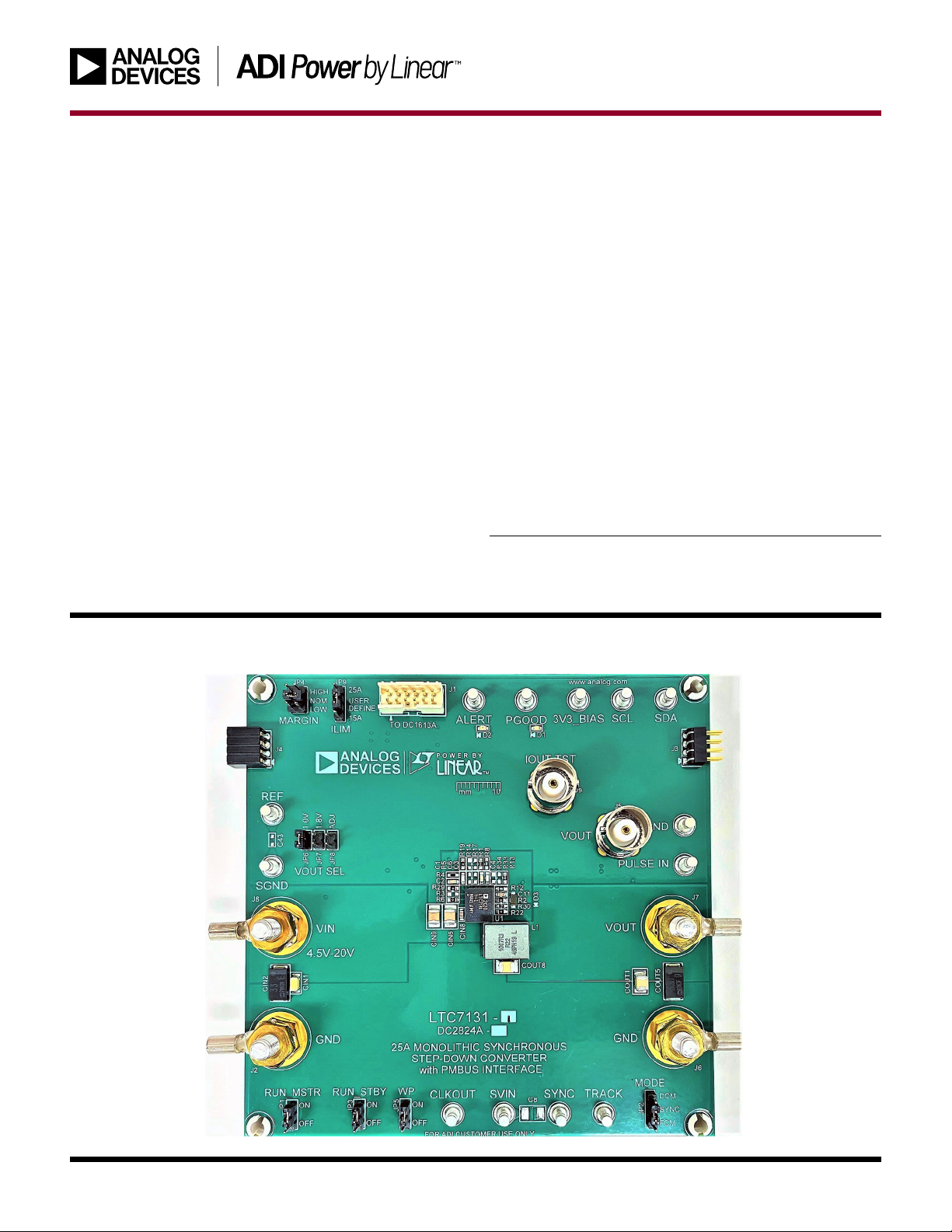
DEMO MANUAL
DC2824A-A
Rev. 0
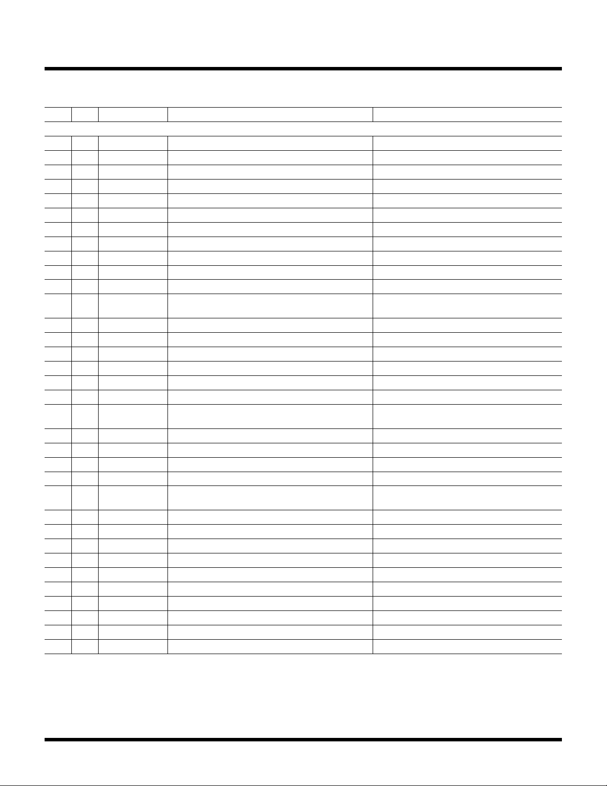
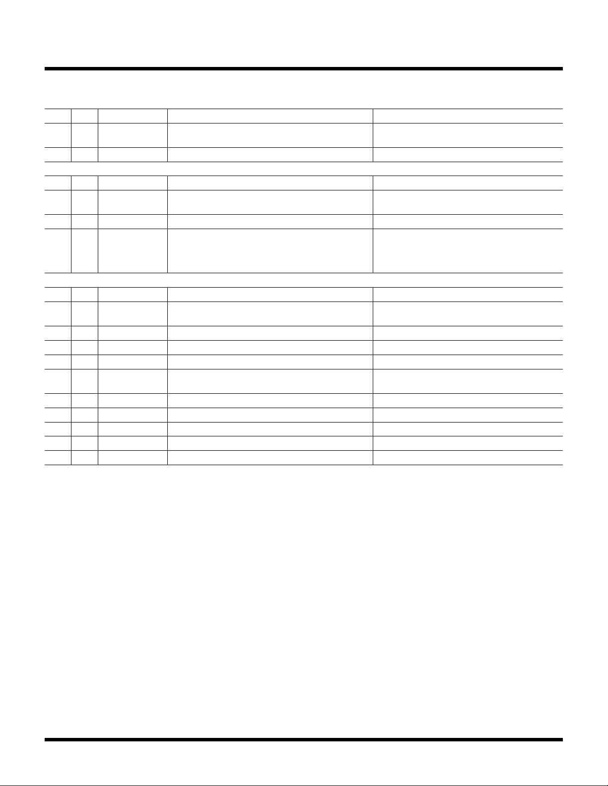
ITEM QTY REFERENCE PART DESCRIPTION MANUFACTURER/PART NUMBER
Required Circuit
1 1 C1 CAP., 47pF, C0G, 50V, 5%, 0603 VISHAY, VJ0603A470JXAAC
2 1 C2 CAP., 4700pF, X7R, 50V, 10%, 0603 AVX, 06035C472KAT2A
3 1 C3 CAP., 0.01µF, X7R, 25V, 10%, 0603 AVX, 06033C103KAT2A
4 1 C4 CAP., 47pF, X7R, 50V, 10%, 0603 AVX, 06035C470KAT2A
5 2 C5, C9 CAP., 0.1µF, X7R, 50V, 10%, 0603 AVX, 06035C104KAT2A
6 1 C7 CAP., 1µF, X7R, 25V, 10%, 0603 KEMET, C0603C105K3RACTU
7 2 C11, CIN8 CAP., 4.7µF, X5R, 25V, 20%, 0603 MURATA, GRM188R61E475ME11D
8 1 C41 CAP., 2.2µF, X7R, 25V, 10%, 0805 SAMSUNG, CL21B225KAFNNNE
9 1 C42 CAP., 0.1µF, X7R, 25V, 10%, 0603 AVX, 06033C104KAT2A
10 3 CIN1, CIN3, CIN5 CAP., 22µF, X5R, 25V, 10%, 1206 AVX, 12063D226KAT2A
11 2 CIN2, CIN4 CAP., 33µF, ALUM POLY, 25V, 20%, 7343 PANASONIC, EEFCX1E330R
12 4 CIN6, CIN7, CIN9,
CIN10
CAP., 10µF, X7R, 25V, 10%, 1210 AVX, 12103C106KAT2A
13 2 COUT1, COUT8 CAP., 100µF, X5R, 6.3V, 20%, 1210 MURATA, GRM32ER60J107ME20L
14 3 COUT5-COUT7 CAP., 330µF, ALUM POLY, 4V, 20%, 7343 PANASONIC, EEF-SX0G331XE
15 1 D1 LED, GREEN, WATER CLEAR, 0603 WURTH ELEKTRONIK, 150060GS75000
16 1 D2 LED, RED, WATER CLEAR, 0603 WURTH ELEKTRONIK, 150060RS75000
17 1 D3 DIODE, SCHOTTKY, 30V, 100mA, SOD-323 CENTRAL SEMI., CMHSH-3 TR
18 4 J2, J6-J8 EVAL BOARD STUD HARDWARE SET, #10-32 ANALOG DEVICES, 720-0010
19 1 L1 IND., 215nH, PWR, FERRITE, 10%, 61A, 0.29mΩ, 10.4mm
× 8.0mm SMD
EATON, FP1007R3-R22-R
20 1 Q1 XSTR., MOSFET, P-CH, 20V, 5.9A, TO-236 (SOT23-3) VISHAY, Si2365EDS-T1-GE3
21 1 Q2 XSTR., MOSFET N-CH, 60V, 300mA, SOT-23 VISHAY, 2N7002K-T1-GE3
22 1 Q15 XSTR., MOSFET, N-CH, 30V, 30A, LFPAK RENESAS, RJK0305DPB-00#J0
23 1 R1 RES., 1k, 1%, 1/10W, 0603, AEC-Q200 VISHAY, CRCW06031K00FKEA
24 6 R2, R6, R19, R22,
R29, R30
RES., 0Ω, 1/10W, 0603, AEC-Q200 VISHAY, CRCW06030000Z0EA
25 1 R4 RES., 6.04k, 1%, 1/10W, 0603, AEC-Q200 KOA SPEER, RK73H1JTTD6041F
26 2 R7, R20 RES., 10Ω, 1%, 1/10W, 0603 VISHAY, CRCW060310R0FKEA
27 5 R8-R10, R12, R58 RES., 10k, 1%, 1/10W, 0603, AEC-Q200 VISHAY, CRCW060310K0FKEA
28 1 R11 RES., 10k, 0.1%, 1/8W, 0603, ANTI-SULFUR, AEC-Q200 VISHAY, TNPW060310K0BEEA
29 1 R13 RES., AEC-Q200, 2.2Ω, 1%, 1/10W, 0603 NIC, NRC06F2R20TRF
30 2 R15, R16 RES., 4.99k, 1%, 1/10W, 0603 PANASONIC, ERJ3EKF4991V
31 1 R18 RES., 18k, 0.1%, 1/10W, 0603, AEC-Q200 VISHAY, TNPW060318K0BEEA
32 1 R27 RES., 200Ω, 1%, 1/10W, 0603 VISHAY, CRCW0603200RFKEA
33 1 R28 RES., AEC-Q200, 127Ω, 1%, 1/10W, 0603 NIC, NRC06F1270TRF
34 1 R68 RES., 0.01Ω, 1%, 1W, 2512, METAL, SENSE PANASONIC, ERJM1WSF10MU
PARTS LIST