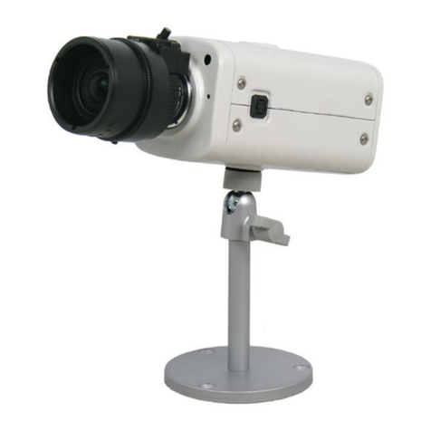
Linear ATMN58KTS User manual

ATM Camera
ATMN58KTS
CAM690ATM
CAM690ATM-28


3
Unpacking
Unpack carefully. This is electromechanical equipment
and should be handled with care. If an item appears to
have been damaged in shipment, replace it properly in
its carton and notify the shipper. If any items are
missing, notify Linear LLC. The shipping carton is the
safest container in which the unit may be transported.
Save it for possible future use.
Service
If the unit ever needs repair service, the customer
should contact Linear LLC for a return product
authorization (RPA) and shipping instructions.
Care and Maintenance
Clean the lens as needed with a soft cloth or Kimtech™
Kim Wipe delicate task wipes. Use a mild detergent
solution or water.
Model Designation
CAM690ATM ATM Camera, 690TVL, Pixim
Seawolf, 3.6mm lens, generic
mounting bracket, 12VDC
CAM690ATM-28 ATM Camera, 690TVL, Pixim
Seawolf, 2.8mm lens, generic
mounting bracket, 12VDC
ATM58KTS ATM Camera Kit, 690TVL, Pixim
Seawolf, 2.8mm lens, mount
bracket for NCR™ 5800 Series
ATM’s, 12VDC
Description
The ATM Camera series features Pixim™ DPS imaging
technology in a compact design. A wide angle lens is
used with an adjustable mounting bracket to provide a
wide range of installation options. A mounting bracket
specific to certain NCR™ ATM’s is included with the
camera in model # ATM58KTS.
Installation Note
Installation of this device should be performed by a
licensed professional where required and should
conform to the National Electrical Code (NEC) and all
applicable local codes.
Hardware Kit
CAM690ATM-xx 1 x Cable Tie
1 x ¼-20 Thumb Screw
1 x ¼” Fender Washer
1 x ATM Bracket
1 x Camera Bracket
1 x #10-32 x 3/8” Screw
1 x #10 Washer
1 x Power Adapter
3 x #4-40 Screws
ATMN58KTS 1 x Cable Tie
1 x ¼-20 Thumb Screw
1 x ¼” Fender Washer
1 x Bracket
1 x Power Adapter
Installation – ATM58KTS
1. This unit ships pre-assembled, ready to install in an
ATM.
2. Refer to installation manual 100 0234 001 AIG for
instructions on installing this camera in a NCR 5800
Series ATM’s.
3. Skip to Appendix A for information on camera
settings.
Installation – CAM690ATM-xx
This camera ships with a pre-installed plastic & metal
base for wall or ceiling- mount installations. If installing
the unit in an ATM, remove the base and attach the
generic ATM bracket.
1. Remove the two screws in the bracket arms (see
Figure 1). Two gaskets surround each screw. Do
not discard these gaskets.
2. If installing the unit using the plastic/metal bracket,
continue to the next section.
3. If installing the unit using the generic metal ATM
bracket, skip to the section titled “Installing Camera
Using ATM Bracket”.
4
Figure 1 - ATM Camera with Plastic/Metal Bracket
Installing Camera Using the Plastic/Metal Bracket:
4. Remove the center screw to separate the metal
bracket from the plastic one.
5. Figure 2 shows the parts referenced in this
section.
6. Use the camera’s metal bracket as a template
to mark the hole pattern in the mounting
surface.
7. Attach the metal bracket to the mounting
surface using the three #4-40 screws included in
the hardware kit, or other appropriate
customer-supplied fasteners.
8. To attach the plastic bracket to the metal
bracket, place the center screw through the
center hole in the plastic bracket, with the
nylon washer under the head of the screw.
9. On the opposite side, place the gasket over the
threads of the screw. The gasket should hold
the screw/washer in place.
10. Align the center screw with the hole in the
metal bracket and tighten the screw.
11. Orient the camera with the “Pixim” logo facing
down (towards the ground). This will ensure the
image is not upside down on screen.
12. Reattach the camera to the plastic bracket using the
two screws and gaskets.
13. Run power and coax to the site. Terminate the coax
cable with a BNC plug.
14. Provide strain relief for the power connection, if
needed.
15. Supply power to the camera.
16. Use a test monitor to ensure the camera is in focus
and pointing in the desired direction.
17. If the camera is out of focus, loosen the nut
surrounding the lens, twist the lens right or left until
the image is in focus, then tighten the nut to secure
the lens in place.
Remove screws, retain gaskets
Metal Bracket
#4-40 Screws
Nylon Washer
Center Screw
Camera
Gasket
Plastic Bracket
Side screws with
gaskets (2 per)
Zip Tie
Figure 2 - Disassembled Camera Bracket

5
Installing Camera Using ATM Bracket
4. Cut the zip tie strain relief being careful not to cut
the power or video wire. Damaged cables are not
covered under this product’s warranty.
HINT: Slide the zip tie off the plastic arm before
cutting the zip tie.
5. Attach the camera bracket to the camera using the
screws and gaskets from step 1. Orient the camera
as needed. The Pixim logo on the camera should
point towards the floor, or the image will be upside
down on screen.
6. Attach the camera bracket to the ATM bracket (see
Figure 3) using the #10 washer and #10-32 screw
from the hardware kit. Adjust the camera bracket
up/down as needed before tightening the screw.
7. Drill a mounting hole in the mounting surface that
will accept a ¼” fastener.
8. Position the bracket under the mounting hole and
attach the camera assembly to the mounting
surface using the thumb screw.
9. Position the camera as needed, then securely
tighten all fasteners.
10. Provide strain relief to the camera cable using the
zip tie from the hardware kit.
11. Supply power to the camera.
12. Use a test monitor to ensure the camera is in focus
and pointing in the desired direction.
13. If the camera is out of focus, loosen the nut
surrounding the lens, twist the lens right or left until
the image is in focus, then tighten the nut to secure
the lens in place.
Camera Configuration
The camera’s on-screen display (OSD) controls are
located on the back of the camera (see Figure 1).
Use the controls to navigate the OSD menu. Features
and options are shown in Appendix A. OSD controls
include Up, Down, Left, Right, and Select (center
button).
Hold down Select to enter the menu.
Figure 3 - Completed Assembly Using ATM Bracket
Thumb screw
ATM Bracket
#10 Washer
#10
-32 x 3/8”
Screw
Camera Brac
ket
Camera

6
APPENDIX A – OSD Features and Settings
To enter the OSD (On-Screen Display) menu, locate the OSD Menu Control shown in Figure 1. Push and hold the select
button to enter the menu. Press Up/Down to navigate between menu items, and press Left/Right to adjust settings.
When exiting, highlight Save&Exit and click the select button to save changes. Highlight Default and press select to reset
the camera to factory defaults.
Feature/Function
Default Value
Description
WDR Control
Medium
Wide Dynamic Range (WDR) is a feature that measures light levels on a
pixel-by-pixel basis so that areas of the image that are too bright are
toned down, and underexposed areas are amplified. This provides
more usable footage in difficult lighting scenarios. Setting the menu
option to “High” indicates the video is being highly processed to evenly
distribute the light levels. A “Low” setting indicates the video is not
altered much from its original state.
BLC (cont’d)
Off
Select the BLC Level (off/low/mid/high) then change the size of the
target region. BLC stands for Backlight Compensation. Use this
feature when the image routinely involves a bright background, a
darker foreground, and the area of interest in the foreground (i.e.
entrance to a store). In normal operation, the camera takes an
average light level to determine the overall screen brightness. This
may cause a dark area in the foreground (i.e. a face) to be too dark to
recognize. The user could use BLC to target where the faces generally
appear. The camera will ignore brighter parts of the image and make
sure the target area is bright enough. The background may appear
washed out at times when the target region is relatively dark.
AGC (Auto Gain Control)
Normal
Select low/normal/high. This feature determines how much the AGC
chip will increase the brightness of incoming light. If the image is too
dark, set the AGC chip increases the signal to provide a brighter image.
A “High” AGC setting means the camera measures the light more often
and adjusts quicker to changing light levels.
Lens Select
DC
This menu item refers to the type of iris used in the camera lens. This
camera uses a Manual Iris lens (i.e. fixed iris).
Flourescent
Off
Certain types of fluorescent lighting can interfere with the camera’s
imager and cause distortion. If the camera is flickering or displaying
wavy lines, switch this menu item from Off to CRR.
Day & Night
n/a
This camera can produce a color image during the day and a
black/white image at night to improve low-light sensitivity. The switch
from color to black/white can be done automatically based on the
input light levels(AUTO), it can be switched using an external trigger
(GPIO, n/a for this unit) or it can be set to color mode only (Off)
Language
English
Select the language for the OSD screen. If your camera is stuck in the
wrong language, exit the menu, hold the center button for 2 seconds,
press Up twice, then the left/right buttons will change languages.
100 0232 003 AIG 03/12
Printed in the U.S.A.
This manual suits for next models
2
Table of contents
Other Linear Security Camera manuals

Linear
Linear D5 User manual

Linear
Linear LINEAR CCM-1A User manual

Linear
Linear LV-B3MDIW-312 User manual

Linear
Linear ChannelPlus 7440 User manual

Linear
Linear LV-D4-2MDI User manual

Linear
Linear CCTV CAMERA RE-BWC1 User manual

Linear
Linear Nice IV400 User manual

Linear
Linear Nice IV400 User manual

Linear
Linear RE-BWC User manual

Linear
Linear CCM-2A User manual