Linergy SPY CENTER BASIC SCB050 Series User manual

USER MANUAL
CENTRAL POWER SUPPLY SYSTEM FOR
EMERGENCY SYSTEM


Please strictly observe all warnings and instructions in this operating manual.
Please keep this manual properly for future reference, and not to use this fi no units when they are
not carefully read all information and warnings described.

PROGRAMMING AND INSTALLATION MANUAL FOR CPS
index
CHAPTER 1
INTRODUCTION
1
CHAPTER 2
INSTALLATION
2
1.1 Intro
1.2 Description of the system
2.1 Intro
2.2 Description of the system
2.3 Positioning
2.4 Rules for making connections
CHAPTER 3
ELECTRICAL CONNECTIONS
3
3.1 Connections battery circuit
3.2 Measures for the maintenance of the batteries
3.3 Rear view of the CPS
3.4 Electrical connection diagram
CHAPTER 5
DISPLAY LCD DISPLAY AND OPERATION KEYBOARD
5
5.1 Functionality LCD display and keypad functionality.
5.2 Switching CPS with mains present
5.3 Switching CPS without mains present
5.4 without mains power off CPS present.
pag.1
pag.6
Pg. 14
pag.18
CHAPTER 7
COMMUNICATION PORTS
1
7
CHAPTER 8
FAILURES AND FAULTS
1
7 1
8
CHAPTER 6
FUNCTIONS
6
6.1 Operation Mode
6.2 Battery Mode
6.3 CPS shutdown with mains present.
6.4 failure mode.
Pg. 25
Pg. 22
Pg. 20

1
INTRODUCTION
Thank you for choosing this product.
This manual provides instructions for safety, installation and of 'equipment operation.
It also allows the most complete product knowledge in order to obtain from it the best service.
Please keep this manual.
WARNING!
The system described in this manual must be used exclusively to 'use for which they have been specifically designed.
Any other use is considered improper and dangerous. The Central Power Supply of the SPY CENTER BASIC series, provide
electrical continuity to every kind of user, in case of lack of main power supply.
Designed specifically for emergency power systems applications, provide a pure sine wave output, and allow different
and various possibilities of load management thanks to differentiated outputs.
When evaluating packaging, the choice of material has been made favoring recyclable materials.
For proper disposal, please separate and identi fi cation of the type of material constituting the packaging according to the table.
Dispose of all materials in accordance with local laws governing the use of the product.
ENVIRONMENTAL PROTECTION
All our products meet the objectives de fi ned in the environmental management system developed by the policy in
accordance with current legislation.
DISPOSAL OF THE PRODUCT
The rescuer contains in its interior materials that in the case of disposal / disposal, are considered re fi toxic and
hazardous waste, such as electronic circuit boards and batteries. Treat these materials in accordance with current
legislation addressing qualified.
CHAPTER 1

2
DESCRIPTION OF THE SYSTEM
This unit online double conversion ensures continuous feeding in of d 'emergency lighting systems or security systems.
The double conversion system has primary to eliminate noise from the main. VFI (Voltage and Frequency
Independent): where in the CPS output voltage is independent of the variations of the mains voltage and frequency variations are
controlled within the limits prescribed by the European Standard (IEC 110-10).
A rectifier converts the alternating current from the direct current network. This charge current batteries and activates the 'inverter.
On the basis of this current l 'inverter generates a sinusoidal alternating current which constantly feeds the loads.
Installations of lighting or security are thus powered entirely by the CPS. If there is a 'power cut, the batteries feed the' inverter.
This manual can be used for the following models:
SCB050 Series
SCB060 Series
SCB080 Series
SCB100 Series
DESCRIPTION OF SYMBOLS
The following symbols shown may appear in the CPS during operation. Therefore, all users should have familiarity to
understand the significance.
Symbols
Meaning Meaning Notice
Attention
Danger High Voltage
Turning ON
Off OFF INVERTER
CPS total shutdown
source of alternating current (AC)
Sources of direct current (DC)
Ground Protection
Audio alarm disabled
Overload indication Batteries
connected
recyclable
Do not dispose of with ordinary garbage
PRINCIPLE OF OPERATION

3
UNPACKING AND INSPECTION
1) Unpack the 'packaging and check the contents inside. The dell 'package
content includes:
CPS;
the manual for the 'installer;
the comunicazone cable to board relay
Relay card (already assembled in 'units)
Battery Box (with battery connected)
Kit cables and fuses.
2) Check 'aspect of the pallet upon delivery to make sure there have not been any damage during transport.
In case there are known defects fi carli immediately to the carrier and to the sender.
CPS
User Manual CD + Safety manual
Cable Kit + fuses
battery Box

4
RULES FOR MAKING ELECTRICAL CONNECTIONS
L 'installation of this equipment must be done by personnel quali fi ed.
The connections must be carried out in the absence of tension.The connections must be carried out in the absence of tension.
Respect the links Phase - Neutral.Respect the links Phase - Neutral.
always to the polarity shown.always to the polarity shown.
L 'reverse polarity cause immediate and irreversible damage to the rescuer. The damage due to reverse polarity are
not in any case covered by the warranty of the SRL Linergy
Use tools with the 'insulated handle. Use tools with the 'insulated handle.
1. Open the terminal cover positioned on the rear PANEL of the rescuer.
We recommend using cable with 4 mm².
The inputs MUST BE PROTECTED BY CIRCUIT BREAKER.
Before making connections open all the thermal magnetic breakers.
2. Make the ground connections to the terminals marked by the conventional symbol.
3. Perform the connection of the output line to the terminals marked OUTPUT, respecting the directions of phase (L) and
NEUTRAL (N).
4. Ensure the cables firmly to the terminals.4. Ensure the cables firmly to the terminals.
The UPS permanently connected to the mains are equipped with a single emergency stop command (ESD = Emergency
Switching Device or EPO = Emergency Power Off) embedded UPS or terminal for connection to an external device that allows l
' remote shutdown of the load and the supply of UPS energy in any operating state. Normally required by the Fire Department.
5. Optional: Perform the connection of 'remote off switch to the contact marked by EPO (Emergency Power Off).5. Optional: Perform the connection of 'remote off switch to the contact marked by EPO (Emergency Power Off).
The EPO contact is normally closed. The rescuer turns off all 'opening of the contact.
.The rescuer is provided with the contact EPO bridged.
1 3

5
PROJECT OF THE FAN TO EN 50272-2 and CEI EN IEC 62458-2
The quantity of air "Q" necessary for the ventilation of a battery compartment, must be calculated according to the formula simpli fi ed:
- 3 3
Q = 0.05 x xnx Igas Crt x 10 (m / h)
= 0.05 vxqxs (v = hydrogen density; q = hydrogen generated; s = safety factor) n = number of battery
elements
Igas = current that produces gas expressed in mA per Ah of capacity delivered, for the charging current fl octant (I fl oat) or for
the rapid charging current (Iboost). Crt = nominal battery capacity (Ah per single battery)
The formula for the calculation of the quantity of air "Q" varies according to the technology of the battery The amount
of the fl ow of air ventilation should be ensured preferably by natural or forced ventilation (arti fi cial).
For natural ventilation, rooms or cabinets of the batteries must have sockets and s fi ati having surface free calculated with the
following formula. A = 28 x Q
3
Q = amount of air ventilation (m / h)
2
A = surface free of the socket and the s fi ato of air (cm)
Example of calculation: for VRLA batteries with AGM technology (maintenance-free batteries) UPS: with 40 12V
batteries (6 2V for battery elements), with capacity of 100Ah
-3 3
Q = 0.05 x xnx Igas Crt x 10 (m / h)
3
0.05 m / Ah
n = number of batteries x N = 240 elements of battery elements (total number of elements) Igas: 1 (mA / Ah) (for
the voltage fl octant) Crt = 100 (Ah)
- 3 3
Q = 0.05 x 240 x 1 x 100 x 10 = 1.2m / h
2
A = 28 x 1.2 = 33,6cm
The quantity of air "Q" necessary for the ventilation of a battery compartment, must be calculated according to when reported by
legislation.
A
h
A
h
h greater than or equal to 2 meters.
VAIN
BEATS
RIE
VAIN
BEATS
RIE
1
3 1 3
6
RULES FOR INSTALLATION
Warning: Before installing the system carefully read the safety instructions:
Do not install 'central unit (CPS) and the battery box next to' water or in moist environments.
Do not install 'central unit (CPS) and the battery box in places exposed to direct sunlight
or heat sources.
Do not obstruct the grids for ventilation posed in the 'housing of the rescuer.
Do not connect appliances or devices that may overload the CPS.
Arrange cables so no one can step on or trip over it.
Nell 'installation of' electrical system dell 'edi fi ce is necessary to provide an appropriate
Disconnection device for short-circuit protection.
the 'emergency system must be installed by quali fi ed service personnel.
The connection to ground is essential before connecting to the end of '
electrical system dell 'edi fi ce.
Do not disconnect the ground wire placed on the CPS or the BACK of 'electrical system terminals
dell 'edi fi ce as this could cause the cancellation of the set up of the PSC protective earth and of all connected loads.
The output terminal of the CPS may also be electrically activated when the rescuer is not
connected to the terminal of 'electrical system dell' edi fi ce, be careful.
To conserve battery life, you must install the 'unity and the box with the batteries in a ventilated area where the
ambient temperature does not exceed 20-25 ° C. A higher temperature can lead to 'excessive stress dell' accumulator
causing an irrevesibile damage.
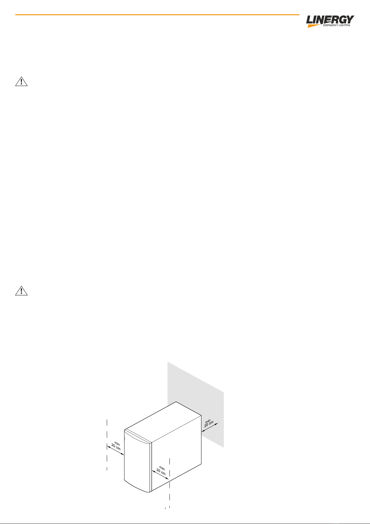
POSITIONING
Install in a dry, well ventilated area
Do not block the cooling vents.
Do not expose to weather (rain, wind, etc.)
Do not install or store the CPS in a non-protected from dust, dirt etc.
Ensuring aeration by placing the apparatus at least 20 cm away from walls
Do not cover the front, rear and side air zones.
CHAPTER 2
7
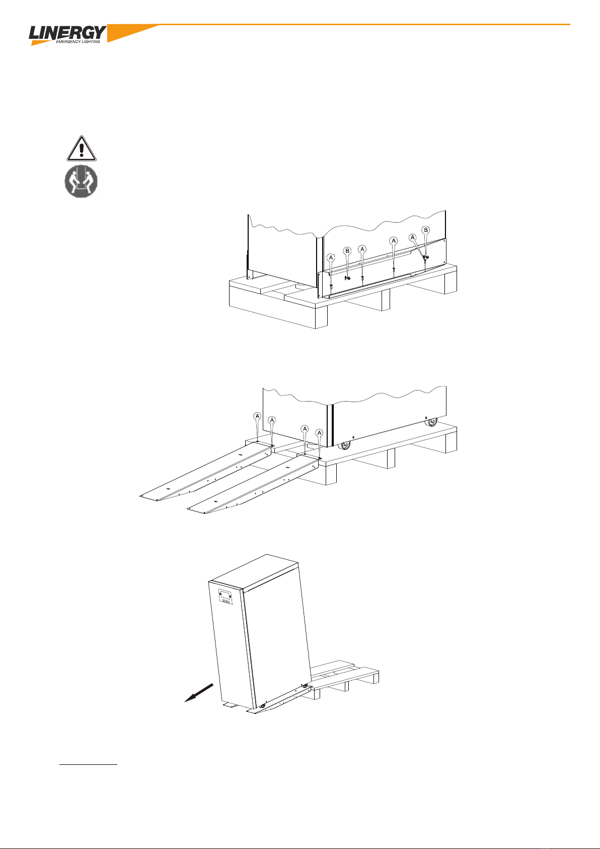
REMOVING THE PARAMEDIC AND THE BATTERY BOX
WARNING: TO PREVENT DAMAGE TO PEOPLE AND / OR EQUIPMENT FOLLOW THE
FOLLOWING.
SOME OF THE FOLLOWING OPERATIONS REQUIRE THE TWO PEOPLE WORK.
Cut the straps. Remove the packaging material.
Remove the 2 brackets that fi xes the CPS to the pallet by unscrewing screws type A and B.
The brackets also serve as slides which were previously removed. Attach the slides to the pallet using type A screws and
being careful to align them in correspondence with the wheels.
Screw the leg fi no bottom so as to distance it as much as possible from the floor of the pallet
Make sure the door is firmly closed.
CAUTION: It is recommended to lower the CPS pushing it from the back, with the utmost caution and
by accompanying the descent. Given the weight of the equipment, this requires the work of two people.
NOTE: Please retain all packaging materials for future use
1
3 1 3
8
ROOM TEMPERATURE
The life expectancy for lead-acid batteries is reduced by half for every increase of 10 degrees with respect to the design
temperature of 20/25 ° C.
Wherever possible, where it is necessary an optimal duty cycle, it is preferable to choose a temperature controlled environment.
It will ensure the proper ventilation, af fi nche any potentially explosive mixtures of hydrogen and oxygen are dispersed before
reaching dangerous concentrations. The ventilation will be designed according to EN 50272-2 "Safety requirements for batteries
and installations".
The EN 50272-2, section 2, is the theme of the batteries of stationary batteries, typically used in applications with CPS. The
standard describes the safety requirements, including the protections from harm generated electricity, electrolytes and explosive
gases. other requirements are also provided for maintaining the functional safety of batteries and installations. The VRLA (Valve
Regulated Lead Acid), better known as sealed lead acid batteries with internal gas recombination, can often be installed without
special safety requirements, since the fl ow of air needed for these batteries is very low.
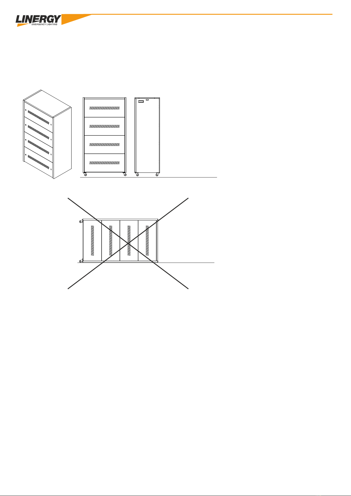
DO NOT TURN THE BATTERY BOX
CORRECT
DO NOT TURN IN NO EVENT
SHALL THE BATTERY BOX
1
3 1 3

9
BATTERY MAINTENANCE
This series of CPS requires minimal maintenance. The batteries used for standard models
are normal batteries LEAD VRLA AGM with life expectancy 10 years. These batteries require minimal adjustments. L 'only
demand is to keep the PSC regularly in the network to charge the batteries and maximize their life. When the machine is
turned on and under the CPS network maintains the batteries charged and also offers a protection against overload or
excessive battery discharge.
The PSC should be fed every 4 to 6 months if not used for a long time.
In countries with high temperatures, the batteries should be recharged every two months. The time of
A standard charge is at least 12 hours.
Under normal conditions, the battery life is about 10 years. If the batteries are not
found in good condition must be replaced as soon as possible.
Batteries should be replaced by qualified.
Replace if necessary Linergy the batteries with batteries of the same type.
Do not replace the batteries individually. All batteries should be replaced at the same
time following the instructions of Linergy Srl.
Normally, the batteries should be charged and discharged every 4- 6 months. The charge should
be carried out after the CPS switches off completely in battery mode, the standard full charging time is 12 hours.
Do not place the battery pack to a heat source, they may crack.
Do not open or cut in any way the batteries, the 'electrolyte is highly poisonous and harmful to
eyes and skin.
Do not connect the positive and negative pole of the batteries, it may cause an electric shock Do not connect
or fire.
Make sure there is no voltage before touching the batteries. The battery circuit is not isolated from the
d 'input circuit. It could occur before a hazardous voltage between the battery terminals and the ground.
1
3 1 3
10
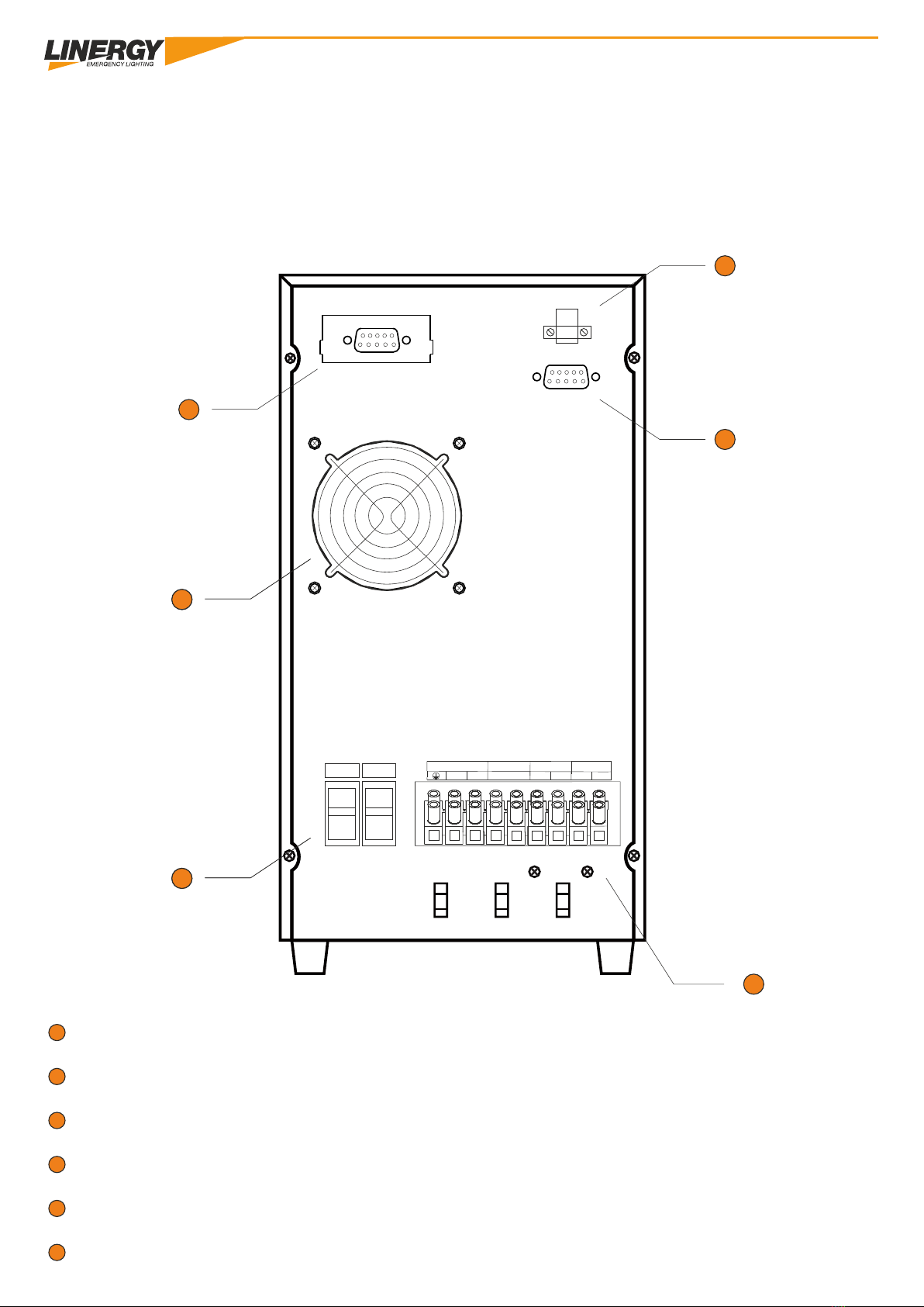
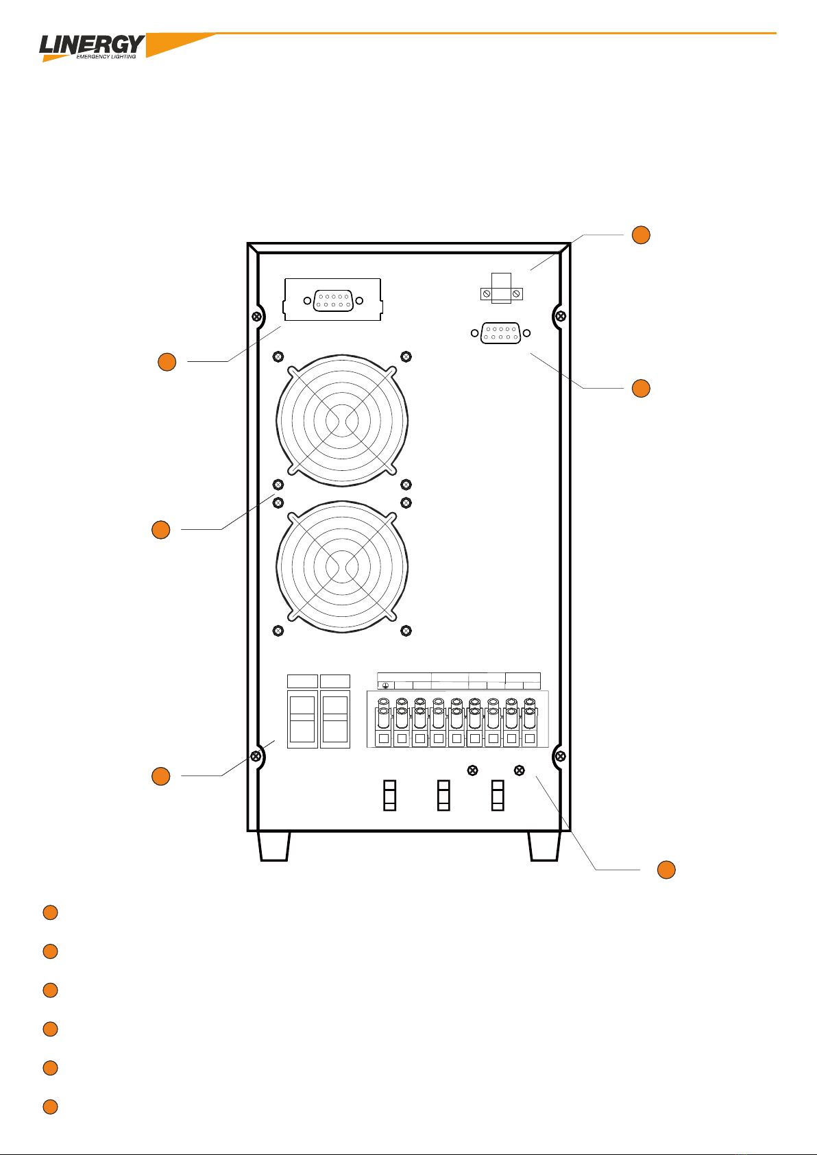
REAR VIEW CPS
1 1 1
1
PROTECTION EARTH EPO
SWITCH
COOLING FANS
SCB050SCB050
SCB060SCB060
2
3
4
5
6
6
1 3
2
4
5
Input Battery
ON
OFF
THE
N +-L1 N1 L2 N2
AC Input Battery Output 1 (SA) AC Output 2 (SE)
1
3 1 3
1
3
RS232
INTELLIGENT SLOT
EPO
11
REAR VIEW CPS
models:
SCB080SCB080
SCB100SCB100
THE
N +-L1 N1 L2 N2
AC Input Battery Output 1 (SA) AC Output 2 (SE)
6
1 3
2
4
5
Input Battery
ON
OFF
1
PROTECTION EARTH
SWITCH
COOLING FANS
2
3
4
5
6
1
3 1 3
1
3
RS232
INTELLIGENT SLOT
EPO

12
OUTPUT NOT MAINTAINED
OUTPUT MAINTAINED
ELECTRICAL CONNECTIONS
battery
Box
1
3 1 3
LN +-L1 N1 L2 N2
AC Imput Battery Output 1 (SA) AC Output 2 (SE)

13
DETAIL CLAMP EPO
Off EPO (Emergency enabled) Activated EPO (Emergency disabled)
INT
11
12
EPO deactivated (Emergency enabled) are visualized on
an external module *
INT
11
12
EPO deactivated (Emergency disabled) with
visualization on external module *
DETAIL WITH TERMINAL EPO FORM OF OPTIONAL cod.SCBMOD STOP FUNCTION (EPO)
The emergency stop function (EPO = Emergency Power-Off) serves the immediate shutdown at a distance of the UPS system
and the connected loads. To this end it is necessary to remove the jumper from the emergency stop plug (on the back of the UPS
system) and connect an external emergency stop switch.
2
Section of the connection cable = 0.5 - 2.5mm (AWG 13-20)
2
Section recommended the connection cable = 1.5mm (AWG 15)
1
3 1 3

14
CONNECT THE BATTERY BOX CPS
The BOX batteries is supplied with the battery circuit already connected to its interior.
BOX To connect the batteries to the machine to use the RED and BLACK CABLE with fast connector (supplied in the kit together
with fuses) connecting them to the BATTERY terminal respecting the polarity as shown in the diagram
L 'reverse polarity cause immediate and irreversible damage to the rescuer. The damage due to reverse
polarity are not in any case covered by the warranty of the SRL Linergy
After connecting the batteries to the PSC Box close the circuit by inserting the fuses provided in the fuse holder on the inside.
CHAPTER 3
THE N +-THE N THE N
AC Input Output 1 (SA) AC Output 2 (SE)
Input Battery
ON
OFF
Battery
BATTERY

15
Input Battery
ON
OFF
POWER CPS
To turn on the central correctly. On the back of the
rescuer
Turn ON the first switch battery, then turn ON switch Input (AC input)
OFF CPS
To properly ATurn the center. On the back of the
rescuer
Turn OFF the first switch input, then turn OFF switch Battery (Battery)
WARNING! FOLLOW THE PROCEDURE.
1
3 1 3
16
IGNITION CPS with electricity mains present (Line mode / AC mode).
1) After making sure that all connections are made correctly place the first 'switch' s entry into the
ON position. At this point the cooling fans start and the SPC lights up in standby mode.
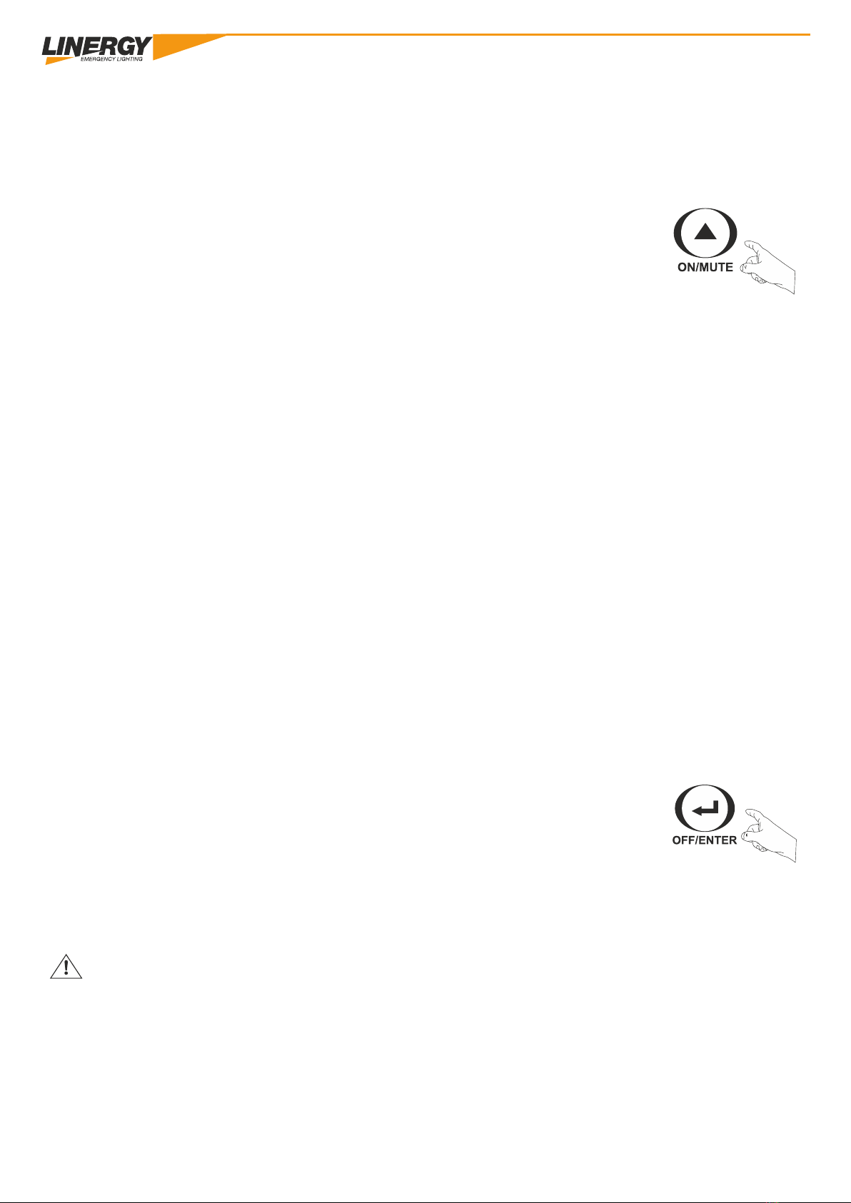
2) To activate the CPS mode, hold down the ON / OFF button continuously for more than one
second.
3) When the CPS is turned on, the control unit initiates a self-diagnosis, which controls the charging
of the batteries and turn on the battery level scale indicating the charging status. After a few seconds,
it turns on the signaling symbol INVERTER LED ACTIVE: in this mode the machine continues to
function, and in case there was a 'power outage, the PSC works in battery mode without interrupting
the mains supply to the load connected output all 'SA output (output 1) while the' IF output (output 2)
turns on.
POWER CPS without main power grid (in Battery mode / battery mode).
1) Hold down continuously for more than one second the power button to turn on the machine. Make sure the 'safety
switch of the battery is ON.
2) In this mode, the PSC operates as if it were connected to the grid except for the fact that the AC input LED is turned off
and the symbol signaling Battery mode is switched on instead.
OFF CPS supplied without mains.
To turn off the CPS must be completely put in the OFF position 'of the mains switch located
behind the machine.
After this hold for more than one second the power button. In this way, power will be interrupted at
'output as soon as the display appears completely off.
Caution is advised to switch off all loads connected to the CPS before turning it off both in battery mode in which
electric network mode present.
1
3 1 3
Other manuals for SPY CENTER BASIC SCB050 Series
1
This manual suits for next models
15
Table of contents
Other Linergy Power Supply manuals


