liniLED Side Photon 1200 User manual
LED strip manual
liniLED® Side Photon 1200
24
V DC
UV RESISTANT
GLOW WIRE
850 °C
FROST
RESISTANT
F
CLEANING AGENTS
RESISTANT
IP40/IP68 SWIMMING POOL
ENVIRONMENT
IK08 SWIMMING POOL
SUBMERSIBLE
MAC
ADAM
2
S D C M
BEND RADIUS
R
30 mm CRI
80+
5
System
RoHS SEA WATER
RESISTANT
V110920


Technical notes 4
Side Photon 1200 - Product drawings 5
Product information 5
Product specications 5
Cable selection 6
Area advice 7
Product care and handling 8
Cutting instructions 9
Solder 11
Connect IP40 13
Uninstalling the connector 15
Welded connector 16
Power supply 17
Symbols 18
liniLED® Side Photon 1200

4LED strip manual | liniLED® Side Photon 1200
Read the instructions and safety precautions before installation, usage and storage of the products to secure safety of the user and reliability of the product.
- Hand over the instructions to the end user and those responsible for installation and usage.
- Triolight B.V. cannot be held responsible for improper handling, product installation, usage or storage.
Handling
- Handle with care.
- The product may not be modied or converted otherwise than prescribed.
- Products are transported in proper packaging. Products should remain packed until installation.
- Take ESD (Electrostatic Discharge) protection measures when handling liniLED® products.
- The products and their components may not be exposed to mechanical, static loads and other tension/compression other than from the product itself.
Installation
- Attention: The power has to be switched o the main power supply or the connection before installation. Not doing so may damage the product.
- Use a suitable LED power supply/driver: 24 V DC constant voltage. Do not drive the product on other voltages than described in their datasheet/products
specications.
- Installation has to be done by a certied professional with knowledge of electrical circuits or a specialised maintenance person known with valid directives.
- General and local construction-, safety- and installation regulations should be respected.
- Use only supplied parts, accessories and required tools as prescribed in the installation manual to guarantee a safe installation and use of the product.
- Products may solely be installed in the areas according to their prescribed IP-rating, IK-rating, temperature range and chemical resistances.
- The LED strip should be installed on an adequate cooling body for proper heat dissipation to ensure smooth operation and long lifetime.
- Do not fasten anything to the product. The same applies when hanging.
- Do not install the product in the following cases:
- Damage is visible on the product or its cables.
- The inside of the product is moistened or dirty.
- The product or its cables have been modied. This could lead to an electrical shock or a short circuit may occur.
- Children may not play unsupervised with electrical products as they cannot judge the dangers in dealing with electrical circuits correctly.
- Use proper mounting surfaces when installing in environments with large variations in temperature and operating lengths more than 2 metres. This should
absorb the stress of any dierence in expansion.
Operation and use
Solely use the product when it’s working correctly. If not, switch the power o immediately and ask an electrical specialist for advice in the following cases:
- Damage is visible on the product and/or the product does not function.
- The product is overheating and/or smoke or steam rises from the product.
- Crackling sounds are noticeable.
Repairs on the installation may only be performed by qualied electricians. Product repairs may solely be done by Triolight B.V.
Cleaning and maintenance
- Attention: Disconnect the power before maintenance and cleaning.
- Dust and dirt accumulated over time should be removed from the light emitting surface to assure optimal functioning of the product.
- Paints, solvents and corrosive cleaning chemicals may not contact and thus aect the product.
Environment and waste
- Exterior decorative lighting should only be used after sunset.
- This product may not be treated as household waste. Dispose of the material through the waste recycling of electrical and electronic equipment.
Warranty
This product comes with a 2 year warranty. Warranty void if:
- The installation guide has not been consulted (installation mistake).
- The installation is not done by a certied installer.
- Local rules and guidelines are not respected.
- The invoice cannot be shown and/or has been altered.
- Damage is caused by negligence, abnormal use or improper handling, use, maintenance and/or cleaning of the product.
Technical notes
5LED strip manual | liniLED® Side Photon 1200
The liniLED® LED strip Top Photon 1200 - White (IP40/IP67*) is a high quality, exible LED strip with an outstanding ecacy. The combination of high quality,
exceptional exibility and a unique co-extrusion technology, allow for an endless range of indoor and outdoor applications. The liniLED® LED strip Top Photon
is available in various white colours.
* Connect the Top LED strips with the liniLED® Top Connector Sets (1 m 11200 or 5 m 11201). Use the liniLED® Top Extension Cord (11208) to extend.
For IP67 usage, combine with the liniLED® Top IP67 Kit (11490) and the liniLED® Top IP67 Extension Kit (11491).
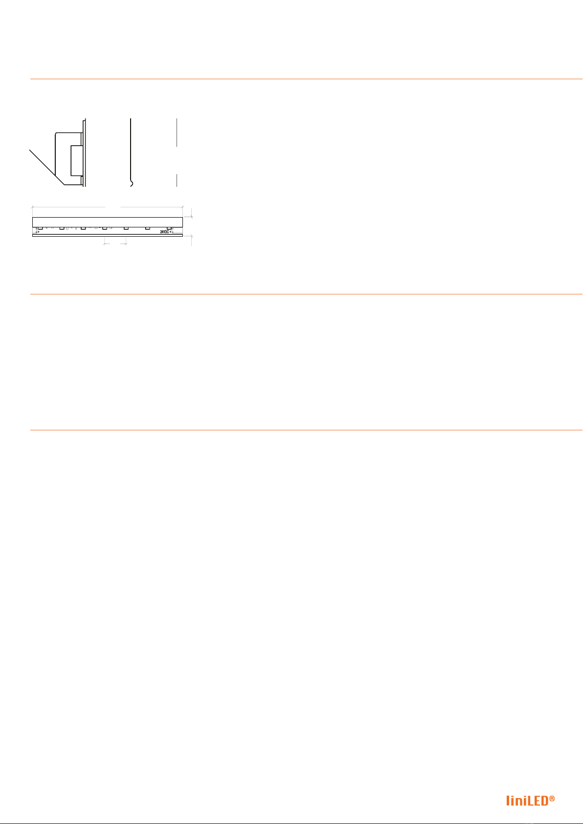
LED strip top view
LED strip front view
12
12
100
12
14.3
Product information
Product specications
Colour LED/m V DC W/m lm/m Temp ˚C Max. Length B70/L50
2000K 70 24 10.6 811 -30...559 m > 60.000 h
2400K 70 24 10.6 958 -30...559 m > 60.000 h
2700K 70 24 8.9 997 -30...559 m > 60.000 h
3000K 70 24 8.9 1023 -30...559 m > 60.000 h
4000K 70 24 8.1 1008 -30...559 m > 60.000 h
6500K 70 24 8.1 1003 -30...559 m > 60.000 h
Max. connection length between -30 °C and -20 °C is 6.3 metres.
Side Photon 1200 - Product drawings

6LED strip manual | liniLED® Side Photon 1200
1. Colour temperature Photon 1200
2. LED strip length 1 m 2 m 5 m 9 m
3. Voltage 24 V DC 25 V DC 24 V DC 25 V DC 24 V DC 25 V DC 24 V DC 25 V DC
4. Cable cross section 0.50 mm - 0.035 Ω/m 36.9 m 72.1 m 17.8 m 35.4 m 6.3 m 13.4 m 2.9 m 6.8 m
0.75 mm - 0.023 Ω/m 55.6 m 108.5 m 26.8 m 53.3 m 9.5 m 20.1 m 4.4 m 10.3 m
1.00 mm - 0.018 Ω/m 73.9 m 144.3 m 35.6 m 70.8 m 12.7 m 26.8 m 5.9 m 13.7 m
1.50 mm - 0.012 Ω/m 111.2 m 217.1 m 53.6 m 106.6 m 19.1 m 40.3 m 8.9 m 20.6 m
2.50 mm - 0.007 Ω/m 185.1 m 361.4 m 89.3 m 177.4 m 31.8 m 67.1 m 14.8 m 34.4 m
Note: Calculations are based on a standard connector with 1 metre cable (0.5 mm).
1= Select colour temperature.
2 = Select LED strip length.
3= Select output voltage.
4= Select cable cross section.
Result = Maximum cable length based
on the cable thickness and power supply
voltage.
Cable selection
-+
Top/Side Connector (1000 mm)
1
2
3
4
Result
Cable selection

7LED strip manual | liniLED® Side Photon 1200
Depending on the installation area of the liniLED® LED strip we oer a range of IP40 and IP68 solutions to cope with external factors. Below the dierent
connectors are displayed for use in dierent environments. See corresponding pages or individual product manual for further instructions.
Indoor environment | (IP20)
Solder
Indoor environment | (IP40) | liniLED® Side Connector set.
Product code: 11202 (1 m), 11203 (5 m)
Wet environment | (IP68) | liniLED® Cast Joint IP68
Product code: 11533
See Manual liniLED® Cast Joint IP68 for installation instructions.
Submersible, chlorine resistant | (IP68) | Welded Connector
Product code: 12293 1m
12294 5m
The connector is pre-assembled to the LED strip.
Area advice
8LED strip manual | liniLED® Side Photon 1200
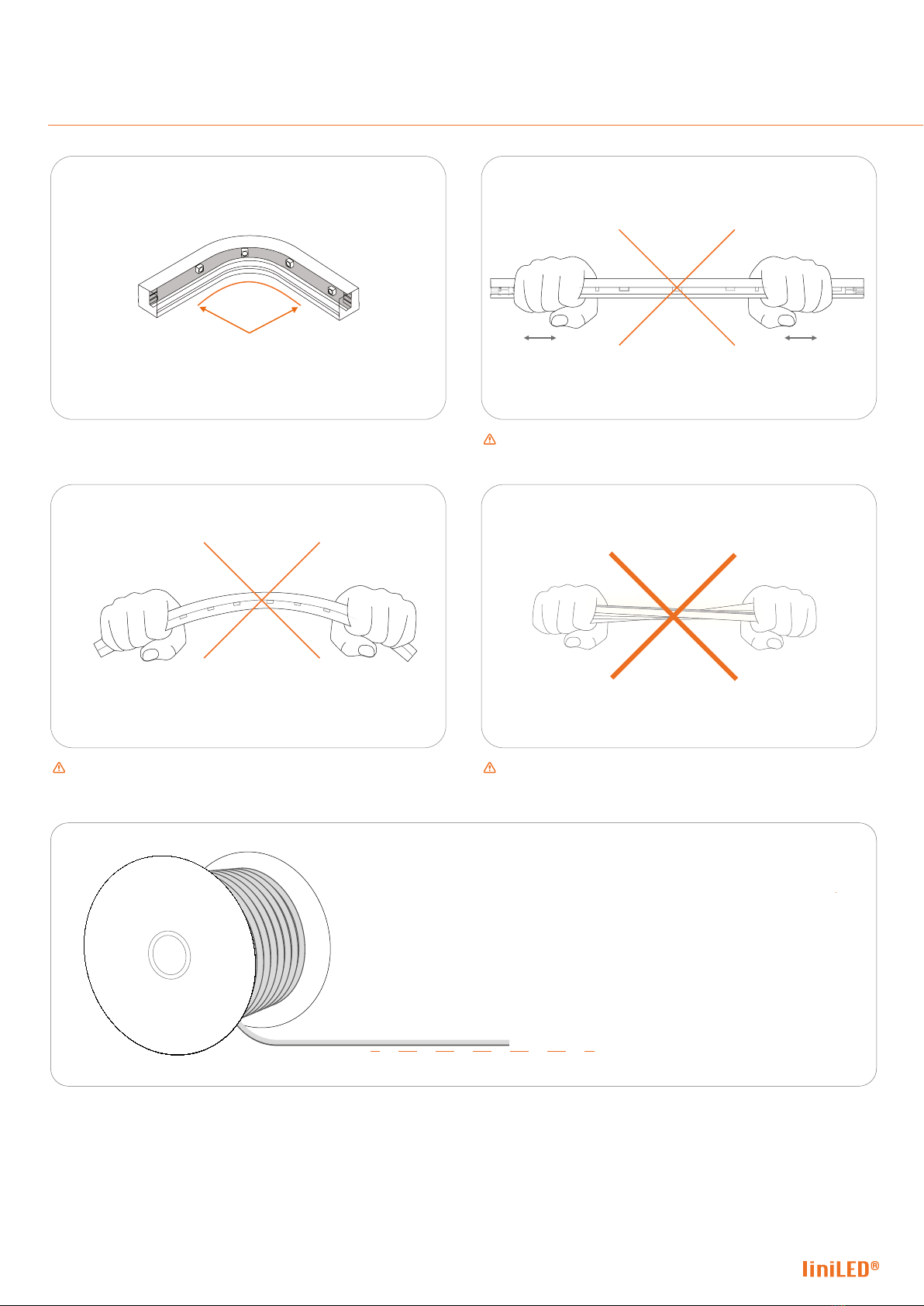
Product care and handling
30 mm
Maximum bending radius is 30 mm. Solely bend up or downward. Do not compress or stretch the LED strip.
Do not bend the LED strip sidewards. Do not twist the LED strip.
The LED strip has to be unreeled on a horizontal surface at the time of installation. Do not unreel the spool of LED strip before installation.

9LED strip manual | liniLED® Side Photon 1200
30 mm
Maximum bending radius is 30 mm. Solely bend up or downward. Do not compress or stretch the LED strip.
Do not bend the LED strip sidewards. Do not twist the LED strip.
The LED strip has to be unreeled on a horizontal surface at the time of installation. Do not unreel the spool of LED strip before installation.
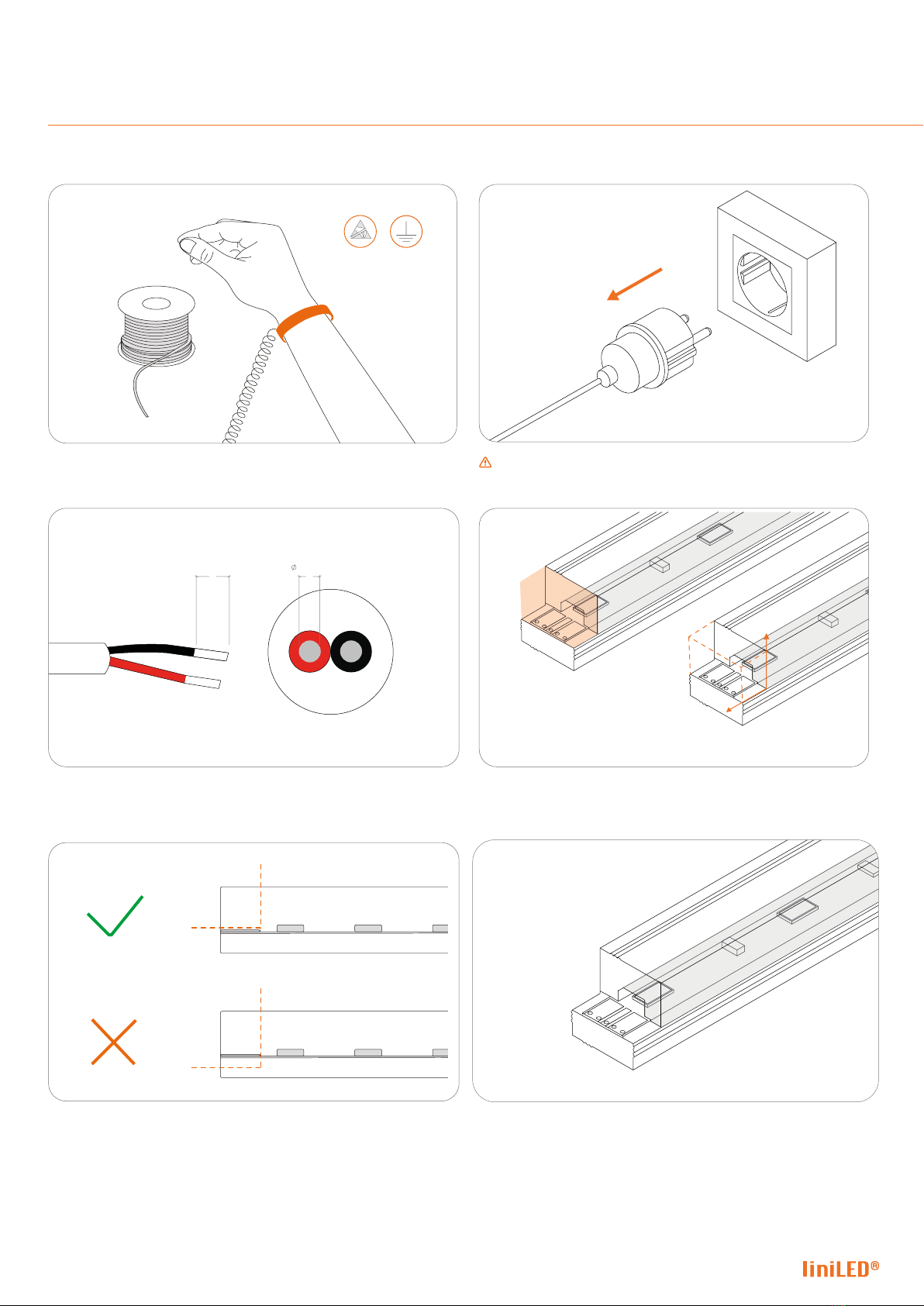
Work in an ESD protected environment. Make use of an anti-static
strap.
Turn o the power before cutting the LED strip.
Side view | Make sure the cut is vertical as illustraded in the image
above.
Top view | Make sure the cut is vertical as illustraded in the image
above.
Top view | Only cut on the dotted lines to prevent damaging the LED
strip.
Dispose of the unnecessary material through waste recycling of
electrical and electronic equipment.
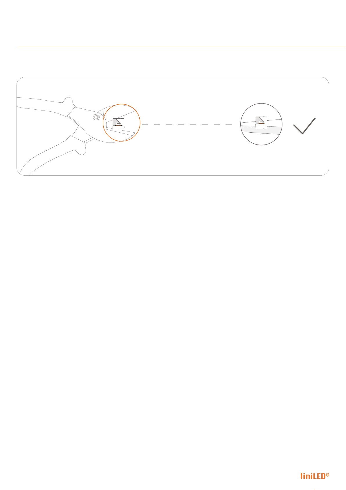
Cutting instructions
5
3
2
4
6
1
10 LED strip manual | liniLED® Side Photon 1200
Place the liniLED® LED strip on the base of the cutting tool. Not doing so may result in a deformed LED strip.
Cutting instructions
11 LED strip manual | liniLED® Side Photon 1200
Solder
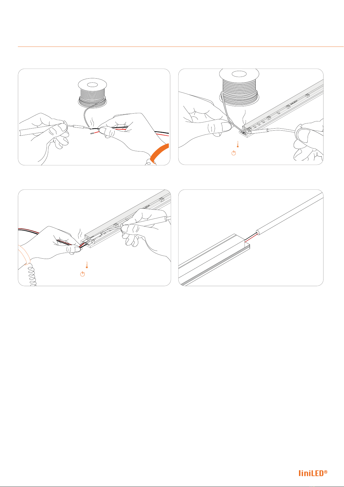
Work in an ESD protected environment. Make use of an anti-static
strap.
Turn o the power. Make sure the wires are not under electric
current.
0.5 mm
2
8 mm
Solder the wires to the PCB. We advise to use a cable with an area not
higher then 0.5 mm
Top view | Only cut the LED strip extrusion on the dotted line of
the extrusion to prevent damaging the PCB. Carefully cut away this
part of the extrusion.
Side view | Do not cut the PCB! The end result after cutting the LED strip extrusion should look
similar to the image above.
5
3
2
4
6
1
12 LED strip manual | liniLED® Side Photon 1200
300°C
Max. 4 sec.
Pre-solder the wires. Pre-solder the connector pads.
300°C
Max. 4 sec.
Solder the wires to the connector pads. Connect the liniLED® LED strip to the power supply (24 V DC) con-
stant voltage.
Solder
9
8
10
7

13 LED strip manual | liniLED® Side Photon 1200
Connect IP40
1
2
3
4
The liniLED® IP40 Connector consists of: End cap (1), Shell (2),
Connector (3), Clamp (4).
Take into account the direction of the arrow on the bottom of the
liniLED® LED strip and allign it with the arrow on the clamp (4).
Place the shell (2) over the LED strip. Make sure the side with the
smallest opening is put on rst.
Front view | Make sure the connector and the PCB are perfectly
horizontally alligned.
Slide the connector (3) sideways into the hollow chamber of the
liniLED® LED strip.
Side view | Slide the clamp (4) over the cable to reveal the
connector (3).

14 LED strip manual | liniLED® Side Photon 1200
Test the liniLED® LED strip before you slide it fully over the clamp (4). Slide the shell (2) entirely over the clamp (4) and push rmly until it
‘clicks‘.
‘ Click ’
Slide the shell (2) partly over the clamp (4).Slide the clamp (4) over the connector (3) and make sure that the
arrow is on the upper side.
Finish the connection by inserting an end cap (1) in the hollow
chamber on the end side of the liniLED® LED strip.
Connect IP40

15 LED strip manual | liniLED® Side Photon 1200
Article number
11202
11203
11209
Description
liniLED® Side Connector set 1 m
liniLED® Side Connector set 5 m
liniLED® Side Extension Cord
The connector should look like this when it is removed.
Firmly grab the outer shell and gently grab the liniLED® LED strip. Gently wiggle the connector and pull in opposite direction.
Firmly press the sides of the shell and pull gently while holding the
cable to remove it.
Uninstalling the connector
16 LED strip manual | liniLED® Side Photon 1200
Welded connector
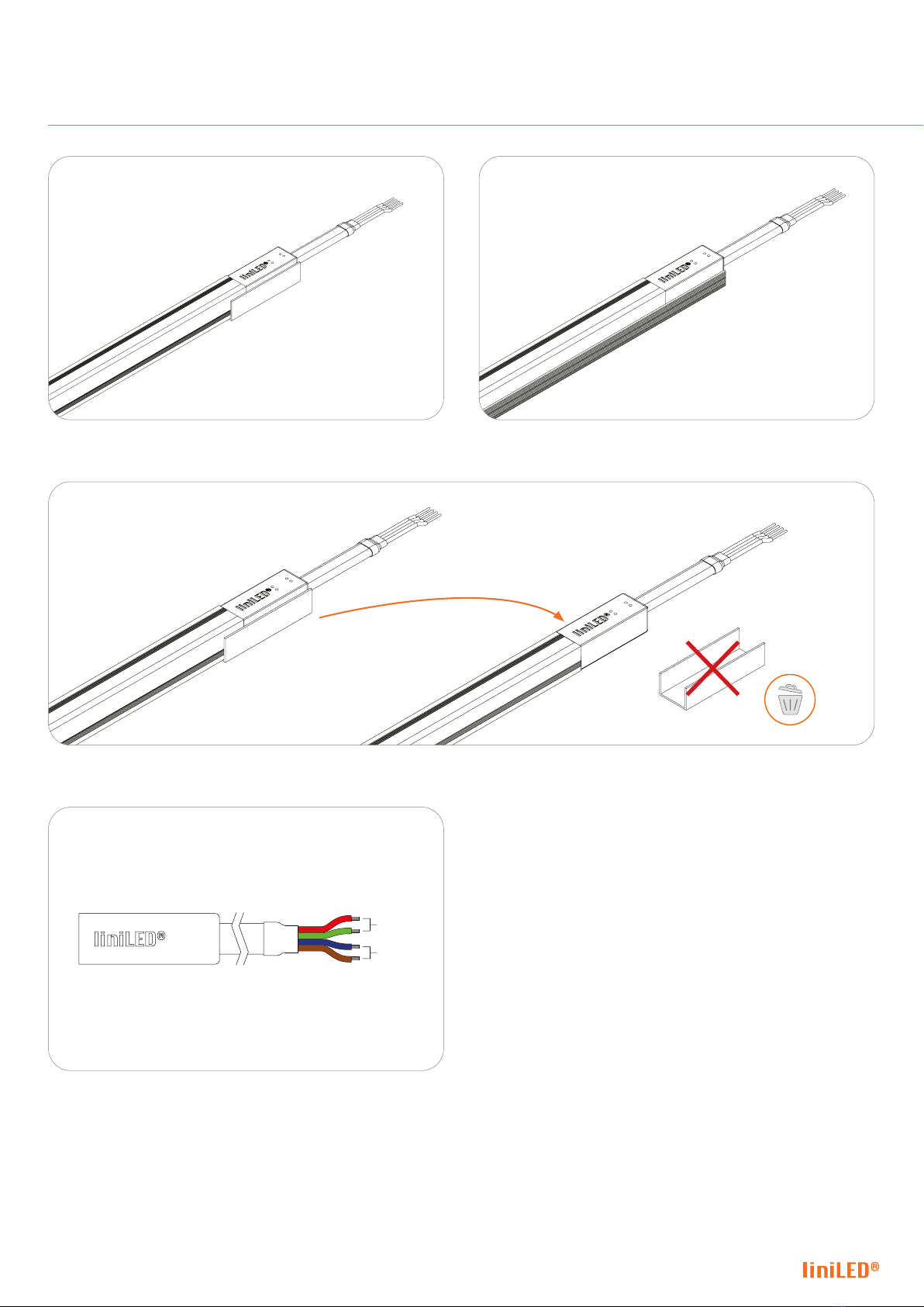
Option 1 Glued profile | Please do not try to remove the U-prole
because this damages the connector.
Option 2 Pre-installed | The liniLED® Welded connector and LED
strip are pre-installed in a xture/prole.
After installation
Option 3 Removable sleeve | The U-prole can be removed after installation, but this will void warranty.
+
-
How to connect | Please use Blue and Brown for + and use Red
and Green for -.
Welded connector

17 LED strip manual | liniLED® Side Photon 1200
Turn o the power before connecting the LED strip to the power
liniLED® Control
(Optional)
L
NPower
Supply
24 V
DC -
+
230 V
AC
Measure output (23-25 V DC)
before installing liniLED® system
Connect the LED strip as indicated in the gure above. The wires should be connected as follows: Red (+) and Black (-).
Insert the power plug.
Power supply
Option 1 Glued profile | Please do not try to remove the U-prole
because this damages the connector.
Option 2 Pre-installed | The liniLED® Welded connector and LED
strip are pre-installed in a xture/prole.
After installation
Option 3 Removable sleeve | The U-prole can be removed after installation, but this will void warranty.
+
-
How to connect | Please use Blue and Brown for + and use Red
and Green for -.
Welded connector

18 LED strip manual | liniLED® Side Photon 1200
Symbols
Manufacturer’s declaration that the product meets the applicable EC directives.
GLOW WIRE
850 °C
Passed glow wire test at 850 degrees Celsius. Global European regulations specify 650 degrees Celsius by default.
This product can be both IP40 and IP68 depending on the conguration and application. See the documentation for the exact IP rating.
IP40/IP68
IP40/IP68
Bending of the LED strip is possible with a radius of ≥ 30 millimetres in the specied direction.
BEND RADIUS
R
30 mm
Electrical appliance class III: this product is designed to be supplied from an extra-low voltage (≤ 60.0 V DC or ≤ 42.4 V AC).
Product can be cleaned with normal cleaning agents.
CLEANING
This product can be applied in seawater and its environment. Elements in seawater will have no harmful eect on the product.
For chemical specications of these elements see the liniLED® material sheet. Verify the IP rating for proper use.
SEA
MAC
ADAM
2
S D C M
White colour consistency up to 2 SDCM ellipse over an entire single strip length. LEDs used are single BIN 3 SDCM ellipse, but their careful
combination in a LED strip during the production process, results in a mixed light through a diusive material which is within a 2 SDCM ellipse
(probability >90%). Due to variability this is not legally binding. The guaranteed colour consistency can be found in the technical specications.
This product can be applied inside swimming pool environments. Elements in the air will have no harmful eect on the product.
For chemical specications of these elements see the liniLED® material sheet. Verify IP rating for proper use.
SWIMMING POOL
ENVIRONMENT
FSuitable for mounting on all surfaces and suitable to cover with insulating material.
RoHS
Restriction of Hazardous Substances (RoHS): product complies with the RoHS directive and each homogeneous material does not exceed
the limits for the materials mentioned under the RoHS directive (Pb, Hg, Cd, Cr6+, PBB and PBDE).
Protected against impact energy of 5 joules.
IK08
IK08
Operating voltage of 24 V DC.
24
24
V D
C
Product is resistant against ultraviolet (UV) light or sunlight. Non-UV resistant products can degrade or discolour fast when exposed to UV light.
UV
This product can be stored and used below 0 degrees Celsius. Verify the minimum storage and operating temperature in the datasheet or manual
for the lowest temperature allowed.
FROST
This product is available on request and can be applied submerged in swimming pools and their environment. Disinfectants will have
no harmful eect on the product. For chemical specications of these elements see the liniLED® material sheet. Verify IP rating for proper use.
SWIMMING POOL
SUBMERSIBLE
This product needs to be disposed of separately from normal household waste so it can be recycled. Verify the IP rating for proper use.
The CRI value of this product is 80 or higher.
CRI
80
+
5
5
System
System guarantee of 5 years when the complete system consist of liniLED® products with the 5 years system warranty logo.
Terms & conditions apply.
Disclaimer
The published information is checked to be as accurate as possible, however Triolight B.V. or any reseller of liniLED® cannot be held liable for any damages resulting
from misprints, errors, modications or outdated information. No legal rights can be derived from this document. Triolight B.V. reserves the right to modify the
information without informing the customers. Please check for the latest version on www.liniLED.com. This product should not be used in applications, devices or
systems where incorrect operation of the product may result in personal injury (includes emergency lighting) without written permission from the board of Triolight
B.V. If nevertheless used in such applications, devices or systems, Triolight B.V. cannot be held liable for any resulting injury. liniLED® is a registered trademark of
Triolight B.V.

19 LED strip manual | liniLED® Side Photon 1200
Disclaimer
The published information is checked to be as accurate as possible, however Triolight B.V. or any reseller of liniLED® cannot be held liable for any damages resulting
from misprints, errors, modications or outdated information. No legal rights can be derived from this document. Triolight B.V. reserves the right to modify the
information without informing the customers. Please check for the latest version on www.liniLED.com. This product should not be used in applications, devices or
systems where incorrect operation of the product may result in personal injury (includes emergency lighting) without written permission from the board of Triolight
B.V. If nevertheless used in such applications, devices or systems, Triolight B.V. cannot be held liable for any resulting injury. liniLED® is a registered trademark of
Triolight B.V.

Table of contents
Other liniLED Lighting Equipment manuals


Popular Lighting Equipment manuals by other brands


Wolf
Wolf ATEX TURBOLITE A-TL44C Operation & maintenance instructions

Command Light
Command Light C-Lite Guide

Eaton
Eaton Halo RL460 Series instructions

SloanLED
SloanLED SignBOX 3 Slim installation guide

kim lighting
kim lighting Hubbell LIGHTVAULT LTV30 installation instructions

Verilux
Verilux HappyLight Liberty Series manual


