FT Technologies FT742 User manual

1 FT742 (4-20mA) –DM Sensors - User Manual
FT TECHNOLOGIES LTD.
SUNBURY HOUSE
BROOKLANDS CLOSE
SUNBURY-ON-THAMES
MIDDLESEX TW16 7DX
TEL: +44 (0)20 8943 0801
FAX: +44 (0)20 8943 3283
WEB: www.fttechnologies.com
E-MAIL: info@fttechnologies.com
A4277-3-EN
November 2017
The FT and Acu-Res logos are registered trademarks of FT Technologies Ltd.
Copyright © 2017 FT Technologies Ltd. All rights reserved.
FT742 - Analogue (4-20mA) Wind Sensor Manual
Direct-Mount Variant

2 FT742 (4-20mA) –DM Sensors - User Manual
Contents
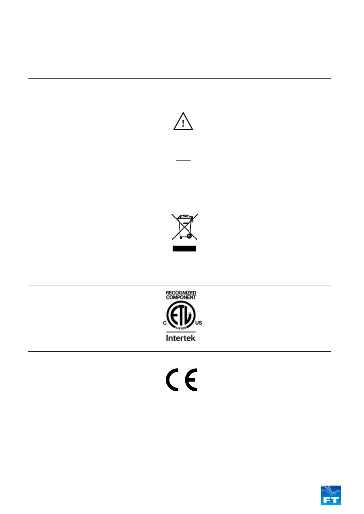
Safety Instructions .......................................................................................4
Consignes de sécurité...................................................................................5
1INTRODUCTION ......................................................................................6
1.1 Product Overview....................................................................................................6
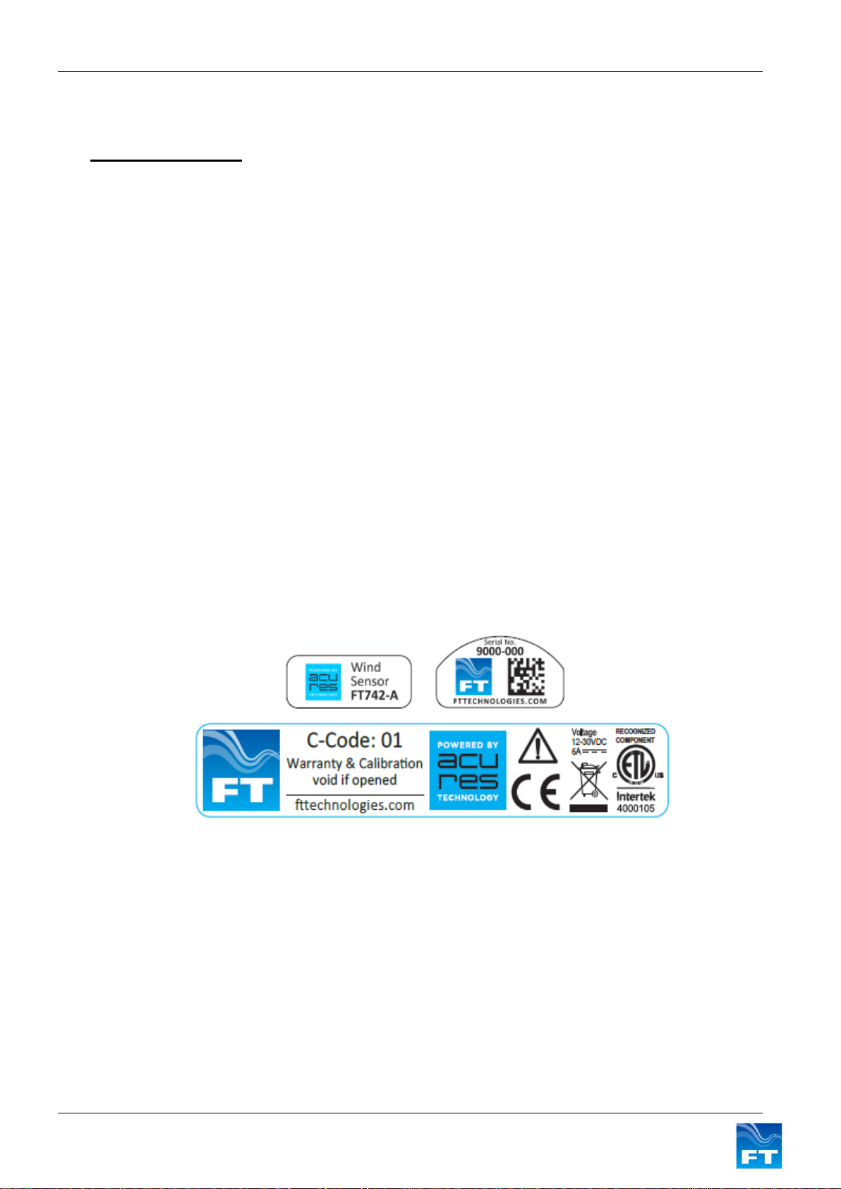
1.2 Build Versions & Labelling.....................................................................................6
1.3 Scope of Use............................................................................................................6
1.4 Disclaimer ................................................................................................................7
2FUNCTIONAL DESCRIPTION.................................................................8
2.1 Technical Performance...........................................................................................8
2.2 Current Loops..........................................................................................................9
2.2.1 Current Loop Characteristics................................................................................9
2.2.2 Using the Averaging Filter.....................................................................................9
2.2.3 Wind Speed Loop .................................................................................................9
2.2.4 Wind Direction Loop........................................................................................... 10
2.2.5 Changing the Wind Datum Direction ................................................................. 11
2.2.6 Error Conditions................................................................................................. 12
2.3 Heater Operation .................................................................................................. 13
2.4 Low Power Operation .......................................................................................... 13
3MECHANICAL & ELECTRICAL INSTALLATION .................................14
3.1 Connector Details................................................................................................. 21
3.2 Cable Details......................................................................................................... 21
3.3 Lightning, Surge & EMI Protection..................................................................... 22
4SERVICE, CONFIGURATION & TESTING............................................24
4.1 Inspection ............................................................................................................. 24
4.2 Fault Finding & Troubleshooting........................................................................ 25
4.3 Returns.................................................................................................................. 26
4.4 The Acu Test Evaluation PC Software............................................................... 27

3 FT742 (4-20mA) –DM Sensors - User Manual
Product Symbols
The following symbols may be used upon the product and within the manual.
Meaning / Description
Symbol
Signification / Description
Warning/ Caution
An appropriate safety instruction should be
followed, or caution to a potential hazard
exists
Avertissement / Attention
Une instruction de sécurité doit être
suivie ou attention portée à un danger
potentiel qui existe.
DC Current only
Equipment operates under Direct Current
(DC) supply only.
Courant continu uniquement
L'équipement fonctionne sous une
alimentation en courant continu (CC)
uniquement.
Product Disposal
In accordance with European directive
2012/19/EU on Waste Electrical and
Electronic Equipment (WEEE), these
product components must be recycled. This
should be done by returning the product to
FT Technologies or by using an appropriate
waste disposal company. This product
should not be disposed of in general waste
of landfill. This product complies with the
RoHS2 (2011/65/EU) directive.
Élimination du produit
Conformément à la directive
européenne 2012/19/EU relative aux
déchets d'équipements électriques et
électroniques (DEEE), ces composants
du produit doivent être recyclés. Cela
doit être fait par le retour du produit à FT
Technologies ou en utilisant une
entreprise d'élimination de déchets. Ce
produit ne doit pas être éliminé avec les
ordures ménagères ou en décharge. Ce
produit est conforme à la directive
RoHS2 (2011/65/EU).
Recognized Component
Sensors marked with the ETL label indicate
that the product conforms to UL Standard
61010-1 and is certified to CSA Standard
C22.2 No. 61010-1.
4000105
Composant Reconnu
Les capteurs marqués avec l’étiquette
ETL indiquent que le produit est
conforme à la norme UL 61010-01 et est
certifié à la norme CSA22.2 61010-01.
CE Mark
The EU Declaration of Conformity complies
with the essential requirements of the
following applicable EMC Directive
2014/30/EU, and carries the CE Marking
accordingly.
Marquage CE
Déclaration de conformité CE de la
compatibilité électromagnétique (EMC)
et marquage CE conformément à la
directive CE 2014/30/EU.

4 FT742 (4-20mA) –DM Sensors - User Manual
Safety Instructions
English
To ensure the safe installation and operation of this product
•The equipment must be installed and integrated;
oUsing suitably qualified and trained personnel
oIn accordance with any regional electrical codes
oIn accordance with the instructions set out in this manual, observing all information, warnings
and instructions
oIn accordance with any other instructions or guidance FT Technologies provides
•To ensure that the product remains compliant with the electrical safety requirements of the UL / CSA
61010-1 Standards it must be;
oConnected to an appropriately approved isolated power supply (for example UL/CSA IEC
60950-1:2005 + A1:2009 + A2:2013) rated 12-30VDC and be current limited (6A Max)
oProtected by UL 1449 listed surge protection devices
oConnected with an approved interface cable (for example UL/ CSA recognised AWM style
21198, rated 300V, 80°C)
•The equipment must only be operated within the range of the specified technical data and used for the
purposes for which it was designed
•The equipment should always be transported in packaging which is appropriate, that will prevent any
accidental damage from occurring.
•Always ensure that any failures or errors from the product cannot cause any damage to any other
equipment or property or cause any other consequential effects.

5 FT742 (4-20mA) –DM Sensors - User Manual
Consignes de sécurité
Français
Pour assurer la sécurité de l'installation et le fonctionnement de ce produit
•L'équipement doit être installé et intégré ;
oÀ l'aide de personnel qualifié et formé.
oConformément à tous les codes électriques régionaux.
oConformément aux instructions figurant dans ce manuel et en observant toutes les
informations, avertissements et instructions.
oConformément à d'autres instructions ou directives que FT Technologies fournit.
•Pour garantir que le produit reste compatible avec les exigences de sécurité électrique de l'UL/CSA
61010-1 normes, l'équipement doit être :
oConnecté à une alimentation agrée convenablement isolée (par exemple UL/CSA IEC 60950-
1:2005 + A1:2009 + A2:2013) de tension nominale 12-30 VCC et avec courant limité (6 A
max).
oProtégé par des dispositifs de protection UL 1449 contre les surtensions.
oConnecté avec un câble d'interface (par exemple UL/CSA reconnu AWM style 21198, de
valeur nominale 300 V, 80°C).
•L'équipement doit être utilisé uniquement dans la plage des données techniques spécifiées et utilisé
aux fins pour lesquelles il a été conçu.
•L'équipement doit toujours être transporté dans un emballage qui est approprié, qui permettra d'éviter
qu'un quelconque dommage accidentel ne survienne.
•En toutes circonstances, garantir que les défaillances ou les erreurs du produit ne puissent pas causer
des dommages à d'autres équipements ou autres biens ou provoquer d'autres effets indirects.

Section 1 - Introduction
6 FT742-DM (4-20mA) –Sensors - User Manual
1 INTRODUCTION
1.1 Product Overview
The FT742-A-DM sensor is designed for general meteorological applications - particularly in harsh
environments such as areas of icing, sand, dust and offshore installation. The solid-state ultrasonic wind sensor
uses acoustic resonance airflow sensing techniques to measure both wind speed and direction. The wind
sensor has no moving parts to degrade or wear-out and is designed for applications requiring high reliability.
Mounting and aligning the sensor is simple. A compass (not supplied) can be used to align the sensor with
magnetic North (0°) using the 0° wind datum marking feature (see Figure 12). For operation in ice-prone areas,
the FT742 is fitted with a highly-effective thermostatically controlled all-body heating system. A three-element
heater is used to ensure heat is evenly distributed over the entire surface area.
FT sensors are configurable and can be factory programmed to the required customer settings, contact FT
Technologies for further details.
Note: The FT742-DM range is not suitable for turbine control applications. The FT742-FF and FT742-PM ranges
are designed for this application.
The standard FT742-DM, when installed to FT Technologies recommendations, is electrically isolated from the
mounting pole, making it unsuitable for conductively-grounded lightning protection schemes. The addition of the
FT035 grounding accessory provides a reliable, low-resistance grounding path. Refer to Section 3.3 or contact
FT Technologies for further information.
1.2 Build Versions & Labelling
Figure 1 shows how to identify a sensor, the serial number and calibration code (if applicable). Section 2.2.3
describes how you can use the wind speed scaling reference to identify the calibration of the sensor.
Additional labels may be attached. Only sensors marked with the Intertek label conform to the UL Standard
61010-1 and are certified to CSA Standard C22.2 No. 61010-1.
Figure 1: Examples of Main Sensor Labels
1.3 Scope of Use
The sensors are designed, manufactured and optimised for high availability.
No promise in part or full can be given to guarantee a wind sensor’s continuous operation, as exceptional
circumstances can occur that may result in the failure of the output from a sensor. Exceptional circumstances
can include;
•Poor installation
•Inadequate inspection
•Power supply failures
•Poor quality electrical connections

Section 1 - Introduction
7 FT742-DM (4-20mA) –Sensors - User Manual
•Lightning exposure
•Physical damage
•Problematic environmental conditions or combination of conditions
1.4 Disclaimer
There are no warranties, representations or conditions, expressed or implied of any kind given in this manual for
any particular design application. The Purchaser should independently undertake sufficient testing to confirm
validity and suitability of any design. The Purchaser assumes all risks and liability in conjunction with the use of
the information given.
Any warranty given by FT Technologies in respect of the equipment is conditional upon the sensor being handled,
installed, integrated and operated in accordance within the guidelines given in this manual.
FT Technologies can take no responsibility for the effectiveness of any sensor lightning protection scheme
implemented.
Information supplied by FT Technologies Ltd. shall not be construed as permission to license to operate under,
or recommendation to infringe any existing or pending patent, patent applications or trademarks.

Section 2 –Functional Description
8 FT742-DM (4-20mA) –Sensors - User Manual
2 FUNCTIONAL DESCRIPTION
2.1 Technical Performance
Sensor Performance1 & 2
Measurement Principle Acoustic Resonance, compensated against variations in temperature,
pressure and humidity.
Wind speed Measurement
Range 0-75m/s
Resolution 0.1m/s
Accuracy ±0.3m/s (0-16m/s)
±2% (16m/s-40m/s)
±4% (40m/s-75m/s)
Wind Direction Measurement
Range 0 to 360
Accuracy 4RMS
Resolution 1
Environment
Temperature Range -40 to +85C (operating & storage)
Humidity 0 - 100%
Altitude 0 - 4000m
Data I/O
Analogue Option 4-20mA, galvanically isolated from power supply lines and case
Format 1x 4-20mA current loop for wind speed (see Section 2.2 for scaling factors)
1x 4-20mA current loop for wind direction (4-20mA = 0 to 360°) (see
Figure 5 for offset options)
Reading Update Rate 10Hz
Configuration Port3RS485 half-duplex, non-isolated relative to power ground
Power Requirements4
Supply Voltage 24VDC nominal (12-30VDC range)
Supply Current (Heater off) 31mA typical for the sensor + 2x current loops (4-20mA)
Supply Current (Heater on) 6A (max) 5 –The heater is thermostatically controlled. Heater power
consumption will depend on the heater energy required to keep the sensor’s
temperature at a user determined set point. The sensor is limited to 4A and
99W5by the default software settings (the current limit can be modified, see
Section 4 or contact FT for details).
Physical
Weight 380g (without size adaptors)
Material Aluminium alloy (hard-anodised)
I/O Connector 8 way
Mounting Method Pipe-Mount screw-fix (33.7mm external diameter EN10255 pipe).
Various size adaptors and pipe-inserts available.
Notes:
1.All specifications subject to change without notice.
2.Specifications calculated with default settings.
3.The Configuration Port is provided to allow the user to change the internal settings of the sensor and to
perform diagnostic testing. This interface should only be used for configuration and test purposes. This
interface is not intended for permanent connection to the computer.
4.The heater set point and current limit can be pre-configured in the factory or adjusted using the FT Acu-Test
Analogue kit.
5.See safety instruction requirements (pages 4 and 5).

Section 2 –Functional Description
9 FT742-DM (4-20mA) –Sensors - User Manual
2.2 Current Loops
2.2.1 Current Loop Characteristics
The wind sensor incorporates two galvanically isolated 4-20mA current loop outputs, one loop for wind speed
and one loop for wind direction. These current loop outputs can be converted into measurable output voltages
with the addition of external resistors.
Each loop should be powered from a DC supply in the range 12V to 30V. A positive supply must be provided to
one of the current loop wires. The other wire must then be connected through a current meter to ground. This is
because the current loops sink current, they do not source it. A common supply can be used if required. Loop
connections are polarity insensitive so that the +ve or –ve loop supply connection can be made to either of the
current loop connection pins. See example wiring in Section 4.4.
The current loops are able to operate over long cable distances; however the overall loop resistance should not
exceed the values given in Figure 2. It is recommended that twisted pair interconnection cabling should be
used. The cable should also include an overall braided screen.
Loop Supply
Maximum Loop Resistance
12V
100 Ω
20V
500 Ω
24V
700 Ω
30V
1000 Ω
Figure 2: Maximum Current Loop Resistance
The wind sensor’s current loop outputs are updated at a rate of 10 times per second. An average of several
readings should always be used for any calculations because single readings can accidentally become
corrupted (see Section 2.2.6).
2.2.2 Using the Averaging Filter
The sensor has an internal averaging filter enabled by default, which dampens the speed and wind direction
outputs by averaging previous data values. By default this feature averages the last 16 readings (1.6s), this can
be factory configured to values 0.1-6.4s in 0.1s increments. It is possible to disable the internal filter (but not
recommended) via the Acu-Test Analogue test software. Contact FT technologies for further details.
Selective Filter
In addition to the averaging filter described above, the sensor has an optional feature called the Selective Filter
that may improve data quality. The scheme allows the user to set a “validity period”, during which the sensor will
exclude invalid readings from entering the averaging filter. The output will freeze on the last previous “good”
reading and only raise an error flag (see Section 2.2.6) once the number of bad readings exceeds the validity
period. This scheme can be enabled by factory configuration. The filter is turned off by default.
2.2.3 Wind Speed Loop
The default wind speed scaling is such that a change from 4 to 20mA represents 0-75m/s. This corresponds to
a scaling factor of 0.2133mA per m/s. The wind speed scaling factor can be factory programmed to the
customer requirements, contact FT for further details. Figure 3 shows the available wind speed scalings.

Section 2 –Functional Description
10 FT742-DM (4-20mA) –Sensors - User Manual
Wind Speed Scaling
References (m/s)
Value @
4mA
Value @ 20mA
Scaling Factor
(mA per m/s)
30
0m/s
30m/s
0.5333
35
0m/s
35m/s
0.4571
40
0m/s
40m/s
0.4000
45
0m/s
45m/s
0.3556
50
0m/s
50m/s
0.3200
55
0m/s
55m/s
0.2909
60
0m/s
60m/s
0.2666
65
0m/s
65m/s
0.2462
70
0m/s
70m/s
0.2286
75
0m/s
75m/s
0.2133
80
0m/s
80m/s
0.2000
85
0m/s
85m/s
0.1882
90
0m/s
90m/s
0.1778
95
0m/s
95m/s
0.1684
100
0m/s
100m/s
0.1600
Figure 3: Wind Speed Scaling Factors
On models where the full scale current has been configured above the maximum speed of the sensor, the
maximum output current will be limited to an amount equivalent to the maximum speed.
The wind speed loop can also be calibrated with non-linear scaling functions. For further information on this
advanced feature contact FT Technologies.
If a wind sensor is replaced care must be taken to ensure that the replacement sensor has
the same scaling. Otherwise the data will have reduced quality.
2.2.4 Wind Direction Loop
The wind direction scaling is such that a change from 4 to 20mA represents 360 degrees (with no dead band)
which corresponds to a scaling factor of 0.0444mA per degree.
The sensor measures the wind direction relative to the 0° datum. The 0° datum location for the sensor is shown
in Figure 4.
The default current loop output when the wind is blowing towards the 0° datum direction is 12mA. If required,
the direction loop can be set to give an output of 4mA at the datum direction. The output options are shown in
Figure 5.

Section 2 –Functional Description
11 FT742-DM (4-20mA) –Sensors - User Manual
Figure 4: Wind Direction (view from above)
Figure 5: Visualisation of direction with 4mA (left) and 12mA (right) current offsets
When operating in the 4mA datum current mode there is a 16mA transition each time the wind direction crosses
the datum. In the 12mA datum current mode the output current varies linearly about the 12mA value as the wind
direction moves around the datum.
2.2.5 Changing the Wind Datum Direction
The datum direction can be electronically rotated (either clockwise or counter clockwise) in 1° increments using
the Acu Vis Analogue software (see Section 4.4) to apply this adjustment. Once the datum offset has been set it
will be retained in the sensor’s Flash memory.
180 225 270 315 0 45 90 135 180

Section 2 –Functional Description
12 FT742-DM (4-20mA) –Sensors - User Manual
2.2.6 Error Conditions
If the sensor detects that a reading may be invalid this is signalled to the data logger by setting the current of
both loops to a value of 1.4mA by default. The error current level can be configured (see Section 4.4) by the user
from 1.4mA up to 3.9mA in steps of 0.1mA.
Note: An optional Overspeed Warning Scheme can be enabled (disabled by default). See below for further
details.
The error condition must occur for more than 0.5 seconds for the current loops to be set to this condition. If an
error occurs for less than 0.5 seconds then the loop outputs will be held at the last valid reading for the duration
of the error.
Figure 6: 4-20mA valid readings range
Always use an average of many readings for any calculations or control decisions because
single readings can accidentally become corrupted.
The data acquisition system needs to not only sample the 4-20mA measurement range, but also should include
logic to process and exclude data if it is outside of this range. The data acquisition system should distinguish
between a status flag error sent by the wind sensor and other out of range readings (see Figure 6) in order to
help diagnose if a fault has occurred with the power supply, cable or wind sensor.
It is important that error flags are not ignored. The datalogger should be able to recognise and interpret error
codes within the data. If errors are ongoing (more than several seconds), a power reset of the sensor should be
performed.
It is recommended that errors are monitored and logged. If the frequency of errors has recently increased, then
inspection of the sensor for physical blockages may be required (see Section 4.1).
Overspeed Warning Scheme
During periods where the sensor detects wind speed beyond the rating of the sensor, the sensor will (by default
settings) indicate an error by setting both current loops to the error flag current level, the same as it does for
other invalid readings. This is to match the legacy behaviour of the FT702LT/D sensor.
An additional feature is included in the FT742 sensor called the Overspeed Warning Scheme (disabled by
default). This scheme can be used to distinguish between overspeed events and other invalid readings. When
enabled and during overspeed events, the scheme works in the following way:
1. The direction current loop will be set to the error flag current level (1.4mA by default).
2. If the wind speed scaling range is equal or above the maximum speed; the speed current loop is set
to maximum (FT742 example: default 0-75m/s range, will read 20mA in overspeed conditions).
3. For scaling ranges below the maximum speed; the speed current loop is set to a value of
20.48mA. (FT742 example, set to 0-40m/s range, set to 20.48mA).

Section 2 –Functional Description
13 FT742-DM (4-20mA) –Sensors - User Manual
The Overspeed Warning Scheme can be enabled in the factory, or by the user using the Acu Vis test software.
2.3 Heater Operation
The sensor is fitted with an integral three-element distributed heater that can be used to prevent icing-up of the
sensor in freezing temperatures. The heater is controlled automatically by the sensor using a user
programmable ‘set point’ temperature. The sensor uses a control scheme which dynamically changes the
current supplied to each individual heater element in order to maintain the programmed set point temperature.
We recommend selecting a suitable set-point temperature for the sensor environment. Factors to consider
include ambient temperature, relative humidity, wind speed and ice/snow conditions. This setting can be
programmed by the factory, or by using the Acu-Test software (see Section 4.4).
It is important to consider cable resistance losses and use a suitably rated cable of an appropriate length. FT
recommends cable types in Section 3.2.
Since the heater circuit is thermostatically controlled, the actual power being drawn from the supply will depend
on the programmed set-point and the environmental conditions (i.e. ambient temperature, wind speed,
precipitation etc.). The maximum power that the sensor can consume is by default limited to 99W (4A with the
heater enabled). The power supply must be rated to provide the maximum power that the sensor can consume.
The maximum current limit of the sensor can be adjusted in software from 0.1 –6A (from the default of 4A and
in increments of 0.1A). The current limit can be programmed at the factory or modified using the Acu-Test PC
software (see Section 4.4). By default the heater requires a minimum of 11V for operation.
2.4 Low Power Operation
The sensor is designed for typical operation at 24VDC, however the sensor can operate below this with reduced
performance between 12-30VDC. By default, the heater will shut down at approximately 11VDC. Below
approximately 8V the sensor may shut down. Lower voltages reduce the overall power consumption and heater
performance.
For further advice on power and heater management strategies, contact FT Technologies.

Chapter 3 –Mechanical & Electrical Installation
14 FT742-DM (4-20mA) –Sensors - User Manual
3 MECHANICAL & ELECTRICAL INSTALLATION
The wind sensor has no moving parts to degrade or wear-out and is designed for applications requiring high
reliability and cold weather operation.
Figure 7: Direct-Mount Wind Sensor
Direct Mount sensors are mounted vertically with the cable connector routed through a 33.7mm (outer diameter)
hollow pipe (EN10255 standard sizes). 4 M6 screws are required to secure the sensor onto the pipe (Figure 11).
The sensor body is manufactured from hard-anodised aluminium and the cavity has a water-repellent coating.
A suitable compass (not supplied) can be used to align the sensor with magnetic North using the convenient ‘N’
alignment marking and the alignment flat. The magnetic North marking indicates 0° and rotates clockwise when
viewed from above (Figure 10). The alignment flat is used with a square-sided compass for rotational alignment.
Magnetic North should be lined up to face parallel to the ‘N’ marking feature (Figure 12).
Ensure the airflow into the sensor is not obstructed or influenced by nearby objects.
In order to keep the pressure within the sensor equalised with the atmospheric pressure, a small breather hole
is located within the connector housing compartment that should not be blocked.
See safety instruction requirements on pages 4 and 5.
The wind sensor installation must be properly designed to ensure the correct operation of
the sensor. This section is for guidance only. It is the responsibility of the designer and
installer to ensure that the installation and its design are safe and fit for purpose. Please
see disclaimer Section 1.4.

Chapter 3 –Mechanical & Electrical Installation
15 FT742-DM (4-20mA) –Sensors - User Manual
The mounting pipe should have a minimum galvanising thickness of 50μm to ensure long-term protection
against corrosion (a relevant galvanising design standard should be considered, for example ASTM A123 or
ISO 1461-2009). Aluminium components of the appropriate grade could be used as an alternative.
At the base of the sensor the mounting pipe meets the sensor (visible when viewed from below). The contact
surface ring (see Figure 8 left image) is hard-anodised and unsuitable for electrical grounding between the
sensor body and ground. This connection should be checked as part of the annual inspection of the sensor as
detailed in Section 4.2. The FT035 grounding accessory can be fitted within the connector chamber and can
provide a low-resistance grounding path to the outer edge of the mounting pipe. The FT035 is comprised of a
coiled metallic spring fitted within the circular inner wall, mating with the outer edge of the mounting pipe, it can
be viewed from the below viewpoint:
Figure 8: Direct-Mount –Connector (View From Below and FT035 Location)
The following replacement parts are available:
FT027
O-ring (3.53 CS x 32.92 ID)
FT031
Size Adaptor 25mm (1”) for FT742-DM (includes a FT033 tapered pipe insert & 4x FT034
self-locking fasteners)
FT032
Size Adaptor 50mm (2”) for FT742-DM (includes a FT033 tapered pipe insert & 4x FT034
self-locking fasteners)
FT033
Tapered Pipe Insert (33.7mm OD)
FT034
1x Self-locking Fastener
FT035
Grounding Accessory

Chapter 3 –Mechanical & Electrical Installation
16 FT742-DM (4-20mA) –Sensors - User Manual

Chapter 3 –Mechanical & Electrical Installation
17 FT742-DM (4-20mA) –Sensors - User Manual
Figure 9: Direct-Mount Wind Sensor (mm)

Chapter 3 –Mechanical & Electrical Installation
18 FT742-DM (4-20mA) –Sensors - User Manual
The sensor measures the wind direction relative to the central datum feature. When the wind sensor is correctly
aligned the wind direction measurements will be as shown in
Figure 10.
Figure 10: Wind Direction (view from above)

Chapter 3 –Mechanical & Electrical Installation
19 FT742-DM (4-20mA) –Sensors - User Manual
1. Pass the cable through the mounting pipe and pipe insert
2. Push the slotted end of the pipe insert into the mounting pipe.
Apply a continuous seam of all-weather adhesive sealant
around each of the two channels, before pushing the insert
fully into the pipe, ensuring the shoulder is flat and any surplus
sealant is wiped away. This insert provides a smooth transition
for the sensor O ring to facilitate easy mounting of the DM with
no damage to the internal O ring (for alternative pipe sizes use
the available size adaptors)
3. Connect the cable to the wind sensor and lower the DM base
onto the pipe
4. Rotate the sensor to align the central North (‘N’ datum,
feature) with magnetic North (or an alternative reference)
5. Tighten the four self-locking fasteners (4x part FT034)
ensuring an even distribution of pressure and firm contact with
the mounting pipe. The fixings use a thread-locking insert and
will provide resistance before they are fully engaged. In highly
corrosive environments (such as coastal installations) the use
of marine grade self-adhesive tape (such as USCGFP by 3M)
is recommended to apply over the top of the mounting
fasteners to ensure ease of removal. In these environments, it
is also beneficial to apply sealant around the base of the
sensor at the pipe interface to reduce build-up of corrosion that
could make sensor removal difficult.
Confirm the installation is safe and appropriate for the
environment.
FT provides optional size adaptors to suit mounting diameters of
25mm (FT031) and 50mm (FT032). Ensure the internal diameter
allows the interface cable to pass through.
Pipe Insert (FT033)
25mm size adaptor (FT031)
50mm size adaptor (FT032)
Figure 11: Direct-Mount Sensor Pipe Installation –Including tapered pipe insert and size adaptors

Chapter 3 –Mechanical & Electrical Installation
20 FT742-DM (4-20mA) –Sensors - User Manual
Figure 12: Direct-Mount Compass Alignment
Table of contents
Other FT Technologies Accessories manuals

FT Technologies
FT Technologies acures FT742-SM User manual

FT Technologies
FT Technologies acures FT742-SM User manual

FT Technologies
FT Technologies acures FT722 User manual

FT Technologies
FT Technologies FT742-D-SM User manual

FT Technologies
FT Technologies FT702LT/D User manual

FT Technologies
FT Technologies FT205EV User manual