Servicevision Scorpio Light Series User manual
Servicevision Bis S.L.
Scorpio
Light Series
10’/17’/23’L
User’s manual v1.04


SCORPIO LIGHT SERIES 10’/17’/23’L - INDEX - Basic information
Version 1.04 May 26, 2022
SERVICEVISION BIS SL
Ríos Rosas, 20 · 08940 CORNELLA DE LLOBREGAT (Barcelona) Spain · Tel. 34 93 223 86 30 · Fax 34 93 223 86 31 3
comercial@servicevision.es · www.servicevision.es
0 INDEX
0INDEX .......................................................................................................................................3
1TECHNICAL INFORMATION.....................................................................................................7
1.1 Basic information................................................................................................................7
1.2 SCORPIO 10’ Technical specifications...............................................................................9
1.3 SCORPIO 17’ Technical specifications.............................................................................10
1.4 SCORPIO 23’L Technical Specifications ..........................................................................11
2PARTS AND COMPONENTS DESCRIPTION.........................................................................12
2.1 Dolly .................................................................................................................................13
2.1.1 Dolly base..................................................................................................................13
2.1.2 Dolly wheels ..............................................................................................................14
2.1.3 Articulated arms.........................................................................................................14
2.1.4 Track wheels.............................................................................................................15
2.2 Column.............................................................................................................................16
2.3 Fulcrum ............................................................................................................................17
2.4 Telescopic arm.................................................................................................................18
2.4.1 Main arm ...................................................................................................................18
2.4.2 Operation bars...........................................................................................................20
2.4.3 Telescopic sections...................................................................................................21
2.5 Electronic box (E.B.).........................................................................................................23
2.5.1 Outside description....................................................................................................23
2.5.2 Inside the electronic box............................................................................................26
2.5.3 Key concepts.............................................................................................................28
2.6 Hand command................................................................................................................29
2.7 Leveling head (L.H.) .........................................................................................................30
2.7.1 Inside the leveling head.............................................................................................31
2.8 Crane accessories............................................................................................................32
2.8.1 Arm accessories........................................................................................................32
2.8.2 Dolly accessories.......................................................................................................36
3SET-UP...................................................................................................................................37
3.1 Assamble the arm (If needed)...........................................................................................37
3.2 Start-up.............................................................................................................................37
3.3 Working modes.................................................................................................................38
3.4 Balance ............................................................................................................................38
4CONTROL DISPLAY INFORMATION .....................................................................................40
4.1 Main screen......................................................................................................................41

SCORPIO LIGHT SERIES 10’/17’/23’L - INDEX - Basic information
Version 1.04 May 26, 2022
4
4.2 Operation menu................................................................................................................42
4.2.1 Limits.........................................................................................................................42
4.2.2 Memories...................................................................................................................43
4.2.2.1 Record a movement ...........................................................................................43
4.2.2.2 Playback a movement ........................................................................................44
4.2.2.3 Configure an existing movement ........................................................................44
4.2.3 Settings menu............................................................................................................45
4.2.3.1 Units...................................................................................................................45
4.2.3.2 Lift ......................................................................................................................45
4.2.3.3 Reset PAN..........................................................................................................45
4.2.3.4 Arc compensation...............................................................................................46
4.2.3.5 Motion Generator................................................................................................47
4.2.3.6 Stop Sequence...................................................................................................48
4.2.3.7 Hand Command (H.C.) buttons ..........................................................................48
4.2.3.8 Screen................................................................................................................49
4.2.4 Auxiliary.....................................................................................................................50
4.2.4.1 Bus Connections ................................................................................................50
4.2.4.2 Command Adjust................................................................................................50
4.2.4.3 Alarms................................................................................................................50
4.2.4.4 ADC Test............................................................................................................51
4.2.4.5 Encoders............................................................................................................51
4.2.4.6 TTL.....................................................................................................................51
4.2.4.7 Default Configuration..........................................................................................51
5SECURITIES & FACTORY RECOMENDATIONS...................................................................52
5.1 Basic safety information....................................................................................................52
5.2 Malfunction risks...............................................................................................................52
5.3 Potential dangers for the user...........................................................................................53
5.3.1.1 Mechanical HAZARDS: ......................................................................................54
5.3.1.2 Electrical HAZARDS:..........................................................................................54
5.4 Protection systems ...........................................................................................................55
5.4.1 Protection against overloads......................................................................................55
5.4.2 Encoder protection system ........................................................................................55
5.4.3 Security circuit board.................................................................................................55
5.4.4 Protection bars and covers........................................................................................55
5.5 System shutdown.............................................................................................................56
6SERVICE & MAINTENANCE...................................................................................................57

SCORPIO LIGHT SERIES 10’/17’/23’L - INDEX - Basic information
Version 1.04 May 26, 2022
SERVICEVISION BIS SL
Ríos Rosas, 20 · 08940 CORNELLA DE LLOBREGAT (Barcelona) Spain · Tel. 34 93 223 86 30 · Fax 34 93 223 86 31 5
comercial@servicevision.es · www.servicevision.es
6.1 Maintenance Requirements..............................................................................................57
6.2 General Maintenance .......................................................................................................57
6.3 Maintenances...................................................................................................................59
6.3.1 Arm rails and rollers...................................................................................................59
6.3.2 First section arm belt .................................................................................................59
6.3.3 Leveling head horizon adjust.....................................................................................59
6.3.4 Leveling head mechanical adjust...............................................................................60
6.4 Services............................................................................................................................60
6.4.1 Belts..........................................................................................................................60
6.4.1.1 LH belt................................................................................................................60
6.4.1.2 Encoder belts .....................................................................................................61
6.4.1.3 Main motor belt...................................................................................................61
6.4.2 Parts replacement .....................................................................................................61
6.4.2.1 Main motor .........................................................................................................61
6.4.2.2 Magnetic limits....................................................................................................62
6.4.3 Upgrade the motor and the electronic box from V1 to V2 on S10’..............................62
6.4.4 Replacement of the Electronic box ............................................................................63
6.5 Electronic Boards .............................................................................................................64
6.6 Loading software to the SERVO/CCU ..............................................................................64
6.6.1 CCU software update ................................................................................................65
6.6.2 SERVO I software update..........................................................................................65
6.7 Driver adjustment .............................................................................................................66
6.7.1 S10’ Arm driver..........................................................................................................66
6.7.2 S17’/S23’L Arm driver................................................................................................67
6.7.3 Leveling head driver..................................................................................................68
7F.A.Q. / COMMON PROBLEMS..............................................................................................69
7.1 Possible problems related to the LH.................................................................................69
7.2 Possible problems related to the column ..........................................................................70
7.3 Possible problems related to the arm................................................................................71
7.4 Fuses ...............................................................................................................................72
8SPECIAL CONFIGURATIONS ................................................................................................73
8.1 Interface with Scorpio Heads............................................................................................73
8.1.1 Set up conditions.......................................................................................................73
8.1.2 Set up........................................................................................................................73
8.1.3 Back-Pan...................................................................................................................75
8.1.4 Tracking mode...........................................................................................................76
Manual distance...................................................................................................................76

SCORPIO LIGHT SERIES 10’/17’/23’L - INDEX - Basic information
Version 1.04 May 26, 2022
6
Distance by focus M.............................................................................................................77
Distance by focus.................................................................................................................77
8.1.5 Tracking tilt................................................................................................................78
8.1.6 Focus tracking...........................................................................................................79
Track crane..........................................................................................................................79
Cinetape & Cinetape M........................................................................................................79
8.2 Matrix mode......................................................................................................................80
8.3 Record memories crane-head ..........................................................................................80
8.3.1 Set up conditions.......................................................................................................80
8.3.2 Analog trigger............................................................................................................81
8.3.3 Digital trigger .............................................................................................................81
8.4 M.G. with Scorpio Focus...................................................................................................82
8.5 Augmented reality.............................................................................................................82
9DOCUMENTATION.................................................................................................................83
9.1 PINOUTS .........................................................................................................................83
9.2 Weights of the cranes.......................................................................................................85
Commonly used weights:.........................................................................................................85
Detailed weights of the cranes:................................................................................................85
Transport weights:...................................................................................................................86
9.3 Other documentation........................................................................................................87
10 CRANE ASSEMBLY PROCESS S10’ ..................................................................................91
10.1 Description of the plywood crates.....................................................................................91
10.2 Crane assembly................................................................................................................91
11 MARKS OF THE EQUIPMENT ............................................................................................93
S10’ CE Mark..............................................................................................................................93

SCORPIO LIGHT SERIES 10’/17’/23’L - TECHNICAL INFORMATION - Basic information
Version 1.04 May 26, 2022
SERVICEVISION BIS SL
Ríos Rosas, 20 · 08940 CORNELLA DE LLOBREGAT (Barcelona) Spain · Tel. 34 93 223 86 30 · Fax 34 93 223 86 31 7
comercial@servicevision.es · www.servicevision.es
1 TECHNICAL INFORMATION
1.1 BASIC INFORMATION
Servicevision provides a completely new concept of telescopic arms to the film and television
industry. The Scorpio light series cranes had been designed to be the swiss army knife of the camera
support equipment. Bringing a new whole and never-ending full range of possibilities and solutions
on the remote camera support.
Another revolutionary feature of the light series is the possibility of displaying whole movement
manually. In manual mode, the director, the photographer, or camera operator will manually perform
the pan, tilt, and telescopic movement of the crane while the arm remains balanced, and the head
levelled to horizon…. as said, a new whole world of possibilities.
The Electronic box to control the crane is extra small and light comparing to the heavy-duty series.
With a removable touch panel display, it keeps all the functions and features developed by Scorpio
for its bigger brothers. The arc compensator, operational limits, selectable speeds, memorization and,
of course, interfaceable with the Scorpio heads to perform back pan and targeting functions.
SCORPIO 10’
THE UNIQUE ALL TERRAIN PORTABLE TELESCOPIC ARM IN THE MARKET.
Mitchel mounted in its Fulcrum; the arm it is compatible with any dolly in the market. Very compact
when retracted and light to make it very easy to move and maneuver when accessing to difficult and
small locations. A main tube plus two telescopic sections give 2.3 mts of telescopic travelling. With a
60kg payload capacity the Scorpio 10’ is robust providing a solid and smooth continuous camera
movement.
The Scorpio 10’ can be provided together Scorpio Dolly. As robust and light as the arm, designed
to be the perfect carrier for either the Scorpio 10, the Scorpio 17’ and Scorpio 23’L. The articulable
arms give the capacity of changing its width in three different positions: for 0.62mts standard dolly
tracks, for 0.41mts tracks, and the last and narrowest configuration of only 0.65 total width, to make
this telescopic arm + dolly accessible almost anywhere (this smallest configuration is not for
operational mode).
Another key component is the telescopic column provided with the Scorpio Dolly. One single
telescopic section, both manually or drill operated and as well as the Scorpio Dolly, the column has
been designed to operate either the Scorpio 10’, 17’ and 23’L arms. Rise the column and reach the
maximum tilt angle and optical height or low down the column and you will be able to get through any
doorway higher than 173cm.
The Scorpio Dolly and the column are optional accessories when purchasing the Scorpio 10’ and
included when purchasing the Scorpio 17’ or 23’L.

SCORPIO LIGHT SERIES 10’/17’/23’L - TECHNICAL INFORMATION - Basic information
Version 1.04 May 26, 2022
8
SCORPIO 17’
THE MIDDLE RANGE LIGHT COMPACT TELESCOPIC CRANE...
Mitchell mounted Fulcrum and with a main arm section with 3 telescopic sections, instead of 2, It
keeps the advantages and characteristics of the Scorpio 10’ but reaching a longer range of 4.05mts
and keeping it in the light and compact crane concept, not affecting the portability and mobility. Using
the very same Scorpio dolly as the Scorpio 10’ warranties flexibility and accessibility to any location.
As well as the Scorpio 10 and Scorpio 23’L, the 17’ belongs to the light line of cranes for Scorpio,
where the arm can be removed very easy and quick, without the need of lifting or towing machine,
only between 2- and 4-men operation can remove, assemble, and transport any of the arms (10’, 17’
and 23’L). The Michell mounted fulcrum allows to mount it in any Mitchell mount support and all the
light series cranes range (Scorpio 10, 17 and 23’L) it gives the possibility of splitting the system in
three separate operational parts, arm and fulcrum, the dolly and the column.
With the same payload capacity (60kgs.), it is the good match to be used in a vehicle, it is also a
versatile small telescopic crane for any shooting situations such as stages, studios, small locations…
a good solution for any job.
SCORPIO 23’L
THE LONGEST RANGE WITH THE LIGHTEST WEIGHT…
This crane is designed to reach up to 5.6meters of telescopic range for a little bit less of payload
capacity. The 40kgs payload warrantiesthe capacity of taking any two axisor small stabilized remote
head in the market with it and be able to reach 23 feet with a very light arm. Following the concept of
the light series, the 23’L crane is also Mitchel mounted fulcrum and it consist in a main tube with 3
telescopic sections, like the Scorpio17 and keeping the concept of compatibility, maneuverability and
portability of these light series.
In comparation to the regular Scorpio23’, this crane has the same length but much lighter and
maneuverable. Mounted in the Scorpio Dolly gives this extra plus in maneuverability and accessibility
to small or difficult access locations. And because is mounted in the same telescopic column allows
to get a 23’ telescopic crane fully mounted and loaded through any doorway.
SCORPIO LIGHT SERIES 10’/17’/23’L - TECHNICAL INFORMATION - SCORPIO 10’ Technical specifications
Version 1.04 May 26, 2022
SERVICEVISION BIS SL
Ríos Rosas, 20 · 08940 CORNELLA DE LLOBREGAT (Barcelona) Spain · Tel. 34 93 223 86 30 · Fax 34 93 223 86 31 9
comercial@servicevision.es · www.servicevision.es
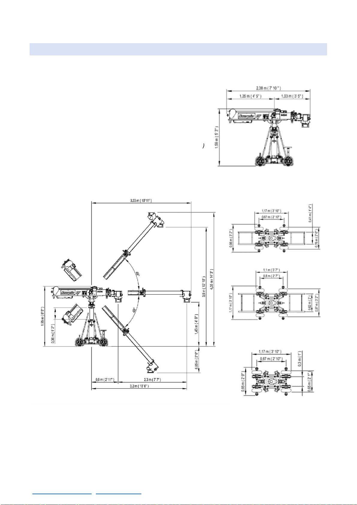
1.2 SCORPIO 10’ TECHNICAL SPECIFICATIONS
Max. length: 3,33m (10’ 11’’)
Min. length: 1,03m (3’ 5’’)
Back length of the arm: 1,35m (4’ 5’’)
Telescopic Range: 2,30m (7’ 7’’)
Max. height: 4,35m (14’3’’)
Telescopic column range: 0,36m (1’2’’)
Payload in Underslung: 60kg (132lbs)
Payload in Over slung: 40kg (88lbs)
Power requirements: DC 30 v/ 40 A (for max speed, max
payload; 20A for normal operation)
Output power for monitor: DC 12 v/ 3 A
Speed of the arm: 1,3 m/s
Weight of the crane empty: 273,4kg. (602.7 lbs.)
Max. Weight when loaded: 544,6kg. (1200.6 lbs.)
Weight of the arm (empty): 68kg. (149.9lbs.)
Weight of the dolly, column & fulcrum: 162kg. (357.2lbs.)
0,41 m (1’ 4’’) TRACKS
0,62 m (2’) TRACKS
SMALLEST CONFIGURATION
(FOR TRANSPORT ONLY)

SCORPIO LIGHT SERIES 10’/17’/23’L - TECHNICAL INFORMATION - SCORPIO 17’ Technical specifications
Version 1.04 May 26, 2022
10
1.3 SCORPIO 17’ TECHNICAL SPECIFICATIONS
Max. length: 5,3m (17’5”)
Min. length: 1,2m (3’11”)
Back length of the arm: 1,7m (5’7”)
Telescopic Range: 4,05m (13’3”)
Max. height: 5,85m (19’2”)
Telescopic column range: 0,36m (1’2’’)
Payload in Underslung: 60kg (132lbs)
Payload in Over slung: 40kg (88lbs)
Power requirements: DC 30 v/ 40 A (for max speed, max
payload; 20A for normal operation)
Output power for monitor: DC 12 v/ 3 A
Speed of the arm: 1,5 m/s
Weight of the crane empty: 338,4kg. (746 lbs.)
Max. Weight when loaded: 744,3kg. (1641 lbs.)
Weight of the arm (empty): 122kg. (268.9lbs.)
Weight of the dolly, column & fulcrum: 166.1kg. (366.2lbs.)
0,62 m (2’) TRACKS
0,41 m (1’ 4’’) TRACKS
SMALLEST CONFIGURATION
(FOR TRANSPORT ONLY)
SCORPIO LIGHT SERIES 10’/17’/23’L - TECHNICAL INFORMATION - SCORPIO 23’L Technical Specifications
Version 1.04 May 26, 2022
SERVICEVISION BIS SL
Ríos Rosas, 20 · 08940 CORNELLA DE LLOBREGAT (Barcelona) Spain · Tel. 34 93 223 86 30 · Fax 34 93 223 86 31 11
comercial@servicevision.es · www.servicevision.es
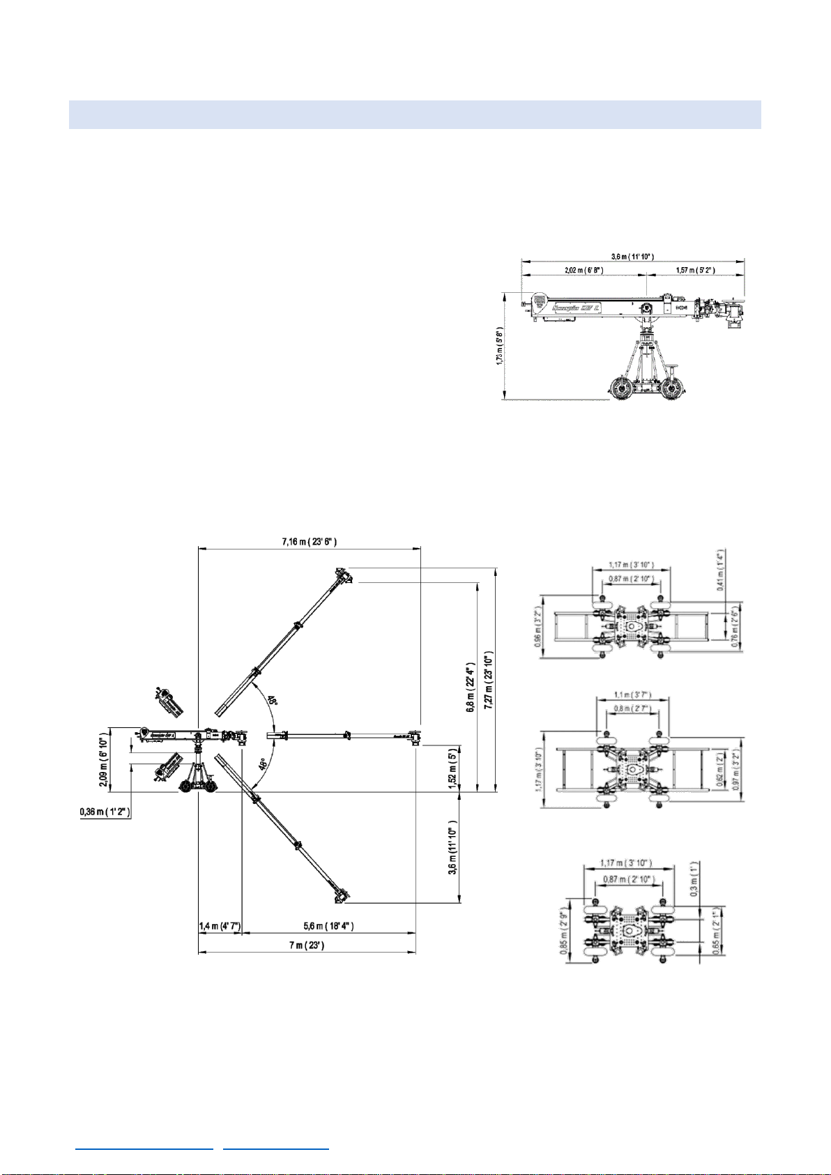
1.4 SCORPIO 23’L TECHNICAL SPECIFICATIONS
Max. length: 7.16 m (23’6”)
Min. length: 1.57m (5’2”)
Back length of the arm: 2.02m (6’8”)
Telescopic Range: 5.6m (18’4”)
Max. height: 7.27m (23’10”)
Telescopic column range: 0,36m (1’2’’)
Payload in Underslung: 40kg (88lbs.)
Payload in Over slung: 40kg (88lbs.)
Power requirements: DC 30 v/ 40 A (for max speed, max
payload; 20 A for normal operation)
Output power for monitor: DC 12 v/ 3 A
Speed of the arm: 1,7 m/s
Weight of the crane empty: 369,4 Kg. (814,4 lb.)
Max. Weight when loaded: 752,8 Kg. (1660lb.)
Weight of the arm (empty): 150kg. (330.7lbs.)
Weight of the dolly, column & fulcrum: 166.1kg. (366.2lbs.)
0,62 m (2’) TRACKS
0,41 m (1’ 4’’) TRACKS
SMALLEST CONFIGURATION
(FOR TRANSPORT ONLY)
SCORPIO LIGHT SERIES 10’/17’/23’L - PARTS AND COMPONENTS DESCRIPTION - SCORPIO 23’L Technical Specifications
Version 1.04 May 26, 2022
12
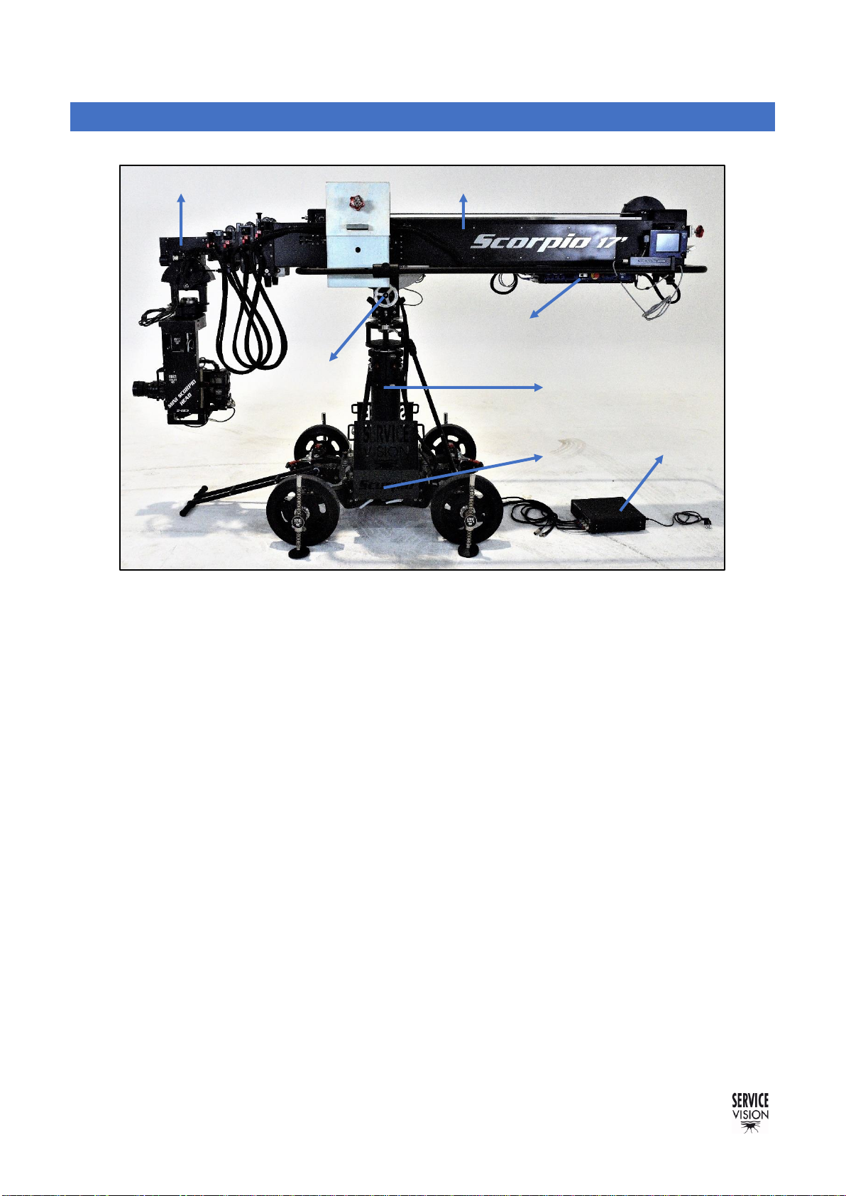
2 PARTS AND COMPONENTS DESCRIPTION
This is a general view of the general components on the telescopic light cranes:
The dolly is the part that locates the crane in the position where it will be operated, either with the
travelling wheels or the dolly wheels. The removable column gives the possibility to mount any
standard Mitchell mount remote head in the base.
The column holds the arm and can be extended or retracted to the desired high to perform different
movements depending on the needs of the user. It has a Mitchell mount on top to attach the fulcrum
or a remote head on it in case it is needed.
The fulcrum is where the arm pivots in the pan and tilt axes. The information from the movement of
the arm is gathered from here. It has a Mitchell mount on its base to operate the arm in different
supports with it.
The Telescopic arm can be extended or retracted in order to reach different positions for the remote
head. It has a counterweight support to keep the arm balanced in any position.
The Electronic box is the main brain of the crane. All the electronic components are located in the
Electronic box and the Leveling Head.
The Leveling Head holds the real horizon automatically on its Mitchell mount when the telescopic
arm moves up or down.
Besides the crane, there are some accessories needed in order to operate and to do regular
maintenances on the crane such as the power unit or the counterweight supports for the dolly. In the
following chapters there will be a brief description of every component on the crane and the
adjustments that can be done by the user on each part.
2.01 Parts of the crane.
Leveling Head
Column
Dolly
Fulcrum
Power unit
Telescopic arm
Electronic box
SCORPIO LIGHT SERIES 10’/17’/23’L - PARTS AND COMPONENTS DESCRIPTION - Dolly
Version 1.04 May 26, 2022
SERVICEVISION BIS SL
Ríos Rosas, 20 · 08940 CORNELLA DE LLOBREGAT (Barcelona) Spain · Tel. 34 93 223 86 30 · Fax 34 93 223 86 31 13
comercial@servicevision.es · www.servicevision.es
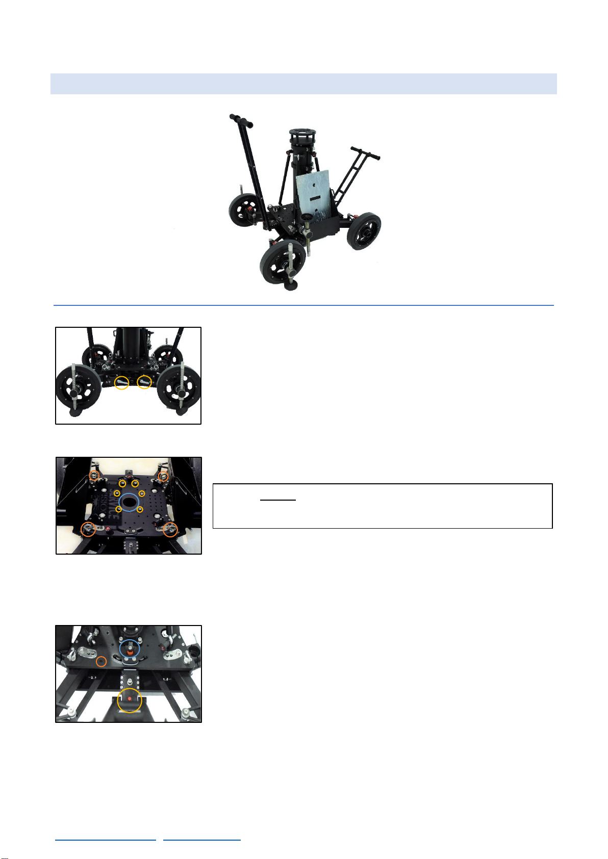
2.1 DOLLY
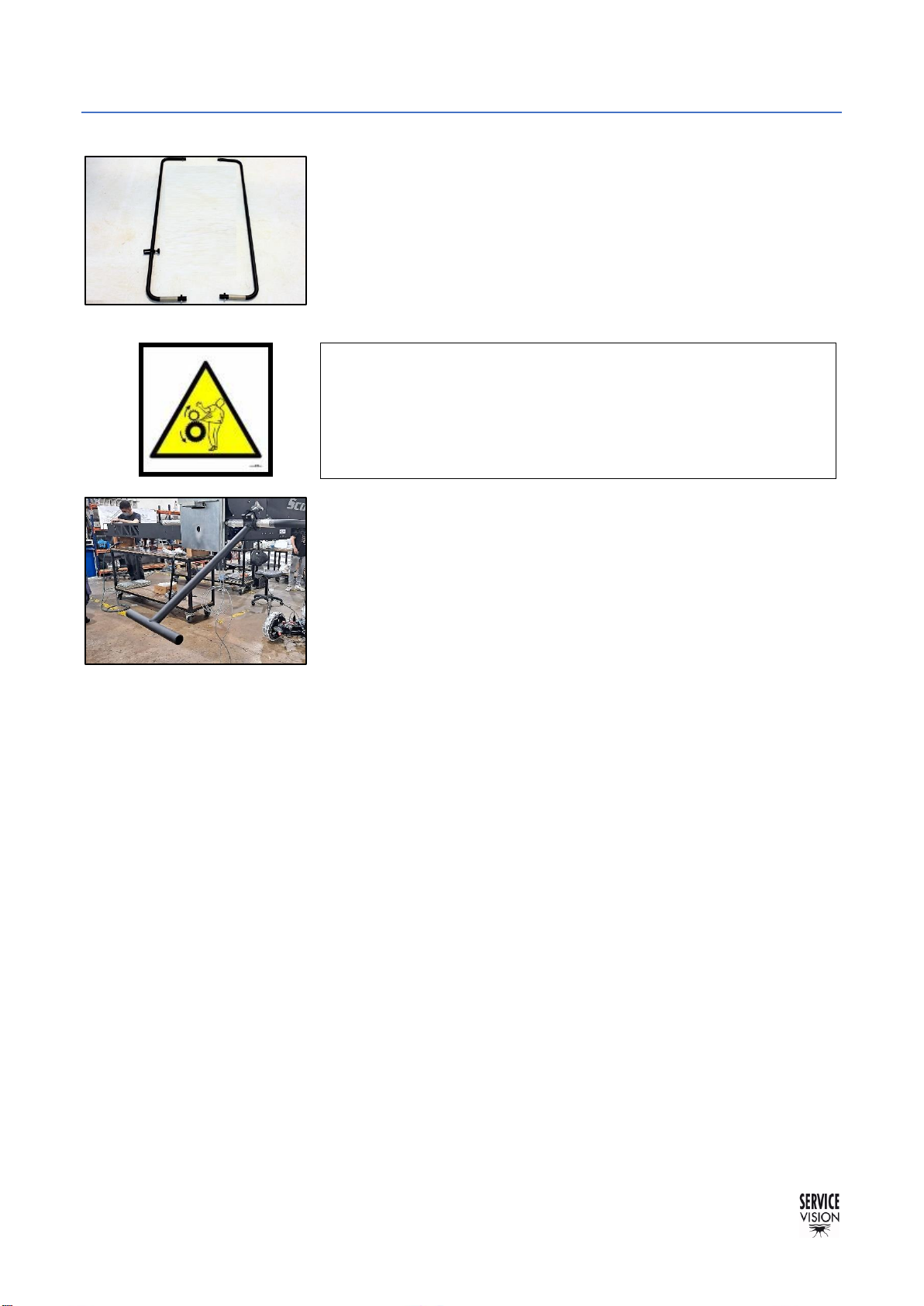
2.1.1 DOLLY BASE The dolly is the base of the crane, it is the same dolly for all the light
cranes, and it can be pushed using 48mm or 50mm aluminum pipes
attached into the supports (A in fig. 02.03). The bars are locked into
the supports by tightening the white handle knobs in the supports.
These supports can also be used as a locking point for the
counterweight buckets. There are four supports for the pushing bars
or the counterweight buckets, two per side.
The dolly also has four strap rings to hold the telescopic arm into the
dolly when the arm is mounted (C in fig.02.04).
In the center of the dolly there is a Mitchell mount support (A in
fig.02.04). If the column is not assembled into the dolly, it is possible
to attach a remote head here. Notice that the dolly’s base is threaded
at M10 in case the user wants to attach different accessories to the
dolly.
The dolly has 2 independent steering handles that allow the
movement of the crane through tight corners. The steering handles
can be locked introducing the locking pin (D10x40mm) in the locking
direction position (fig.02.05). There is a storage position for the locking
pin (C in fig.02.05) in case it is not locking the direction.
It is possible to easily remove the steering handle by unscrewing the
screw (DIN912 M10x30mm) next to the steering locking knob on the
steering handle support. This friction knob (C in fig.02.05), is used to
apply friction on the vertical movement of the steering handle.
02.02 Light cranes Dolly.
A- Supports for pushing bars.
02.03 Dolly sideview.
A–Mitchell mount.
02.04 Dolly base.
B–Column attachment threads.
C–Strap rings.
02.05 Direction detail.
A–Locking pin.
B–Steering lock knob.
C–Storage pin position.
Note: Do not lift the crane from the strap rings. If the crane
needs to be lifted, use straps under the chassis.
SCORPIO LIGHT SERIES 10’/17’/23’L - PARTS AND COMPONENTS DESCRIPTION - Dolly
Version 1.04 May 26, 2022
14
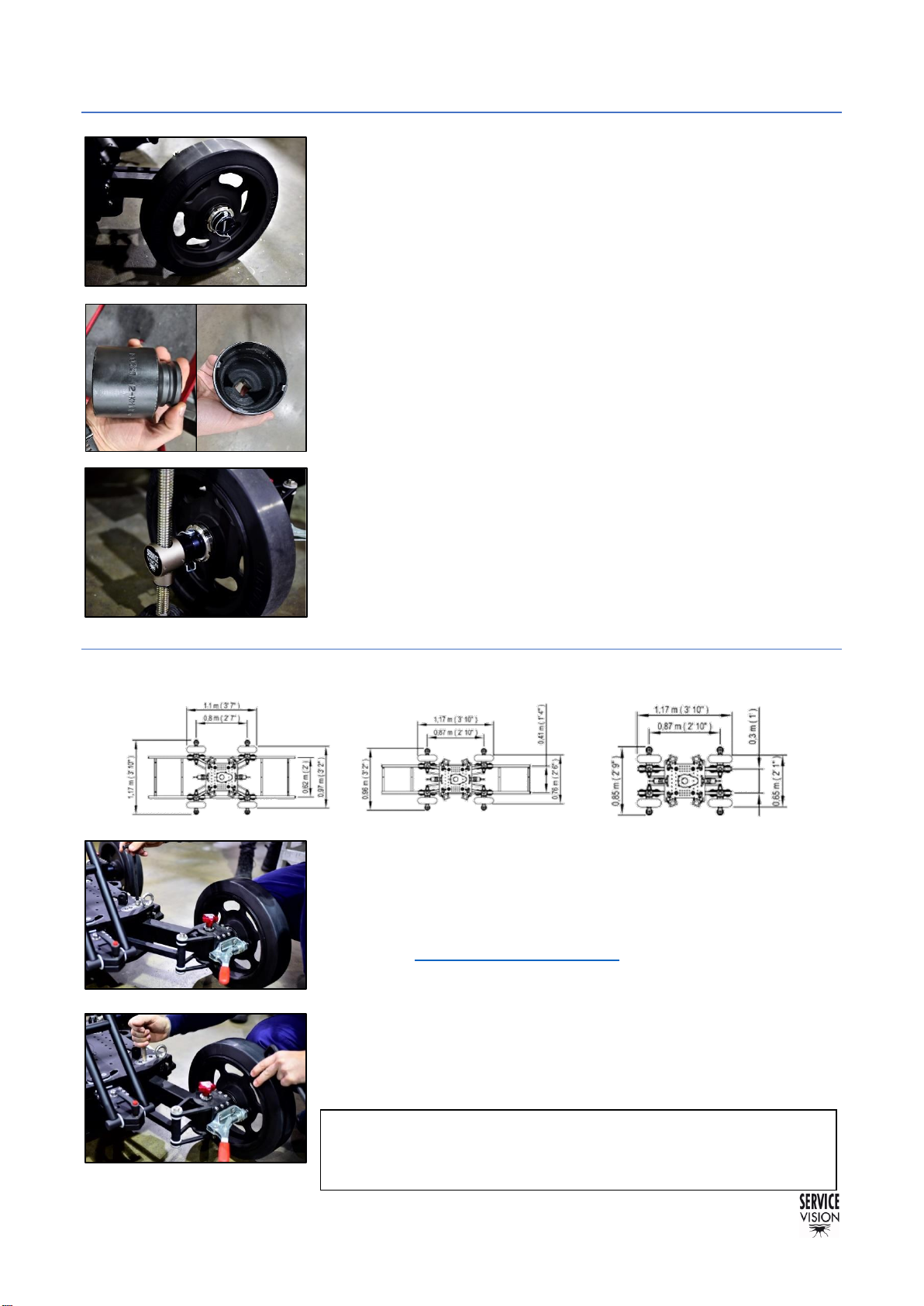
2.1.2 DOLLY WHEELS The wheels are attached to the dolly with KM-11 nuts. To remove
the wheels, remove the pin on the hub and loose the KM-11 (metric
55x2) nut using a 6 teeth KM tool or cutting 2 teeth from a 4 teeth tool
(fig.02.06b).
On the inner side there are the pressure brakes of the wheels (red
handle on fig.02.09). The holes inside the wheel hubs are prepared to
receive the leveling jack’s shafts and hold them with the locking pins
for them(08x60mm). There is the possibility to change the wheels to
pneumatic wheels to move the crane through rough terrains (Ref.
7474).
There is one leveling jack for each wheel. To move the crane
around, they can be removed to reduce the width of the base. To
operate the crane, the 4 of them need to be touching the ground and
they may be used to level the base. To introduce the leveling jack,
remove the locking pin, introduce the shaft of the jack through the
wheel hub and lock it with the pin. Then bring the pad down using the
24mm ratchet wrench provided with the crane.
2.1.3 ARTICULATED ARMS
To change the dolly from one configuration to another the leveling
jacks must be mounted in the wheels, and it can be done with the
crane fully assembled. The telescopic arm needs to be strapped to
the dolly. It is not needed to remove the counterweights or the remote
head, but the arm needs to be completely retracted and secured with
the pin (see chapter 2.4 Telescopic arm). Use all the leveling jacks to
lift the dolly until the wheels can spin freely. Then, one at atime, loose
the screw on the base of the articulated arm (DIN912 M12x160mm)
and move the leg tothe desired position with the hands tolock it again
with the same screw (fig.02.09-02.10). Repeat the process for the rest
of the dolly’s articulated arms and lowerthe dolly base untilthe wheels
touch the ground.
02.07 Leveling Jack attached.
02.06 Rubber wheel with locking pin.
0,62 m (2’) TRACKS
0,41 m (1’ 4’’) TRACKS
SMALLEST CONFIGURATION
02.08 Dolly configurations.
02.10 Changing the dolly’s arm position.
02.09 Loosen the arm screw.
Note: The smallest configuration is only for transport, it is not
safe to operate the crane with the dolly in this configuration.
02.06b Socket KM tool with 2 teeth cut.
SCORPIO LIGHT SERIES 10’/17’/23’L - PARTS AND COMPONENTS DESCRIPTION - Dolly
Version 1.04 May 26, 2022
SERVICEVISION BIS SL
Ríos Rosas, 20 · 08940 CORNELLA DE LLOBREGAT (Barcelona) Spain · Tel. 34 93 223 86 30 · Fax 34 93 223 86 31 15
comercial@servicevision.es · www.servicevision.es
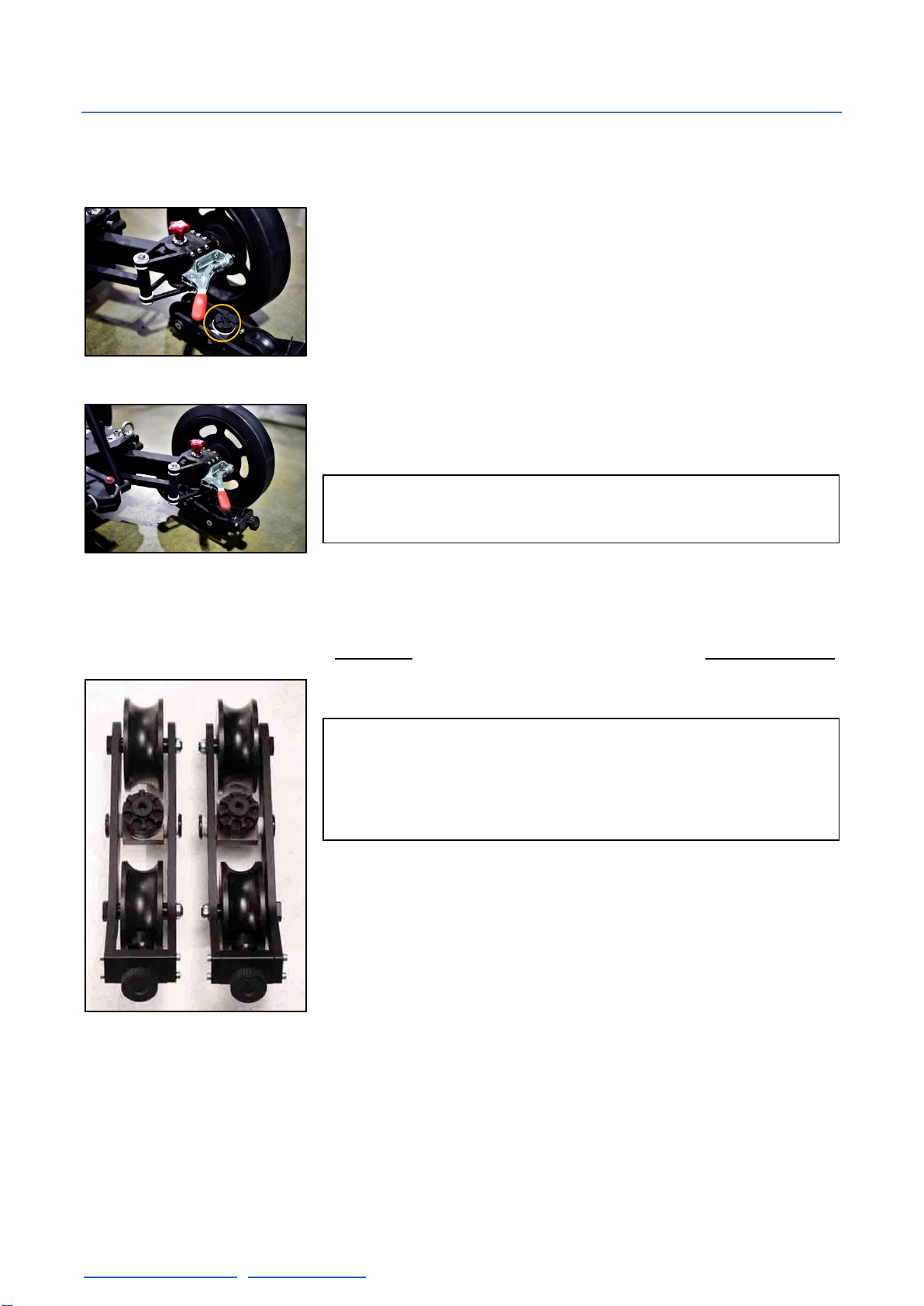
2.1.4 TRACK WHEELS
The dolly can be used indifferent tracks depending on the articulated arms configuration. To do this,
the track wheels need to be assembled into the dolly as shown in this chapter:
To fix or remove the tracking wheels they need to be introduced
under the chassis of the dolly, next to the rubber wheels with the
positioner pin of the track wheels facing top (fig. 02.11).
Once the pin is aligned under the hub, it can be locked in place by
screwing the red knob on top. In case it is needed, this red knob can
be removed by pulling it up and unscrewing it at the same time.
Once the track wheels are assembled, the crane can be introduced
into the tracks using a ramp. In case the user wants to stop the dolly
in any position, there are brakes on each track wheel to lock it in place.
The leveling jacks can also be used as brakes.
Notice before assembling the track wheels that there are 2 of them with a movable axis side to side
and 2 fixed. This is to correct the minor differences between both sides of the track. To make this
system work properly, mount the same kind of track wheels (movable or fix) at the same dolly’s side.
Important note: When using the travelling wheels, DO NOT
leave the crane mounted in tracks overnight, the track wheels
may get flat if they are long periods of time in the same
position.
Note: Ensure that the track is leveled before mounting the
crane on it.
02.11 Track wheel disassembled.
A–Pin from the track wheels.
02.12 Track wheel assembled.
02.13 Different track wheels.

SCORPIO LIGHT SERIES 10’/17’/23’L - PARTS AND COMPONENTS DESCRIPTION - Column
Version 1.04 May 26, 2022
16
2.2 COLUMN
The dolly comes with a two-section telescopic column with a Mitchel mount support on top.
It is attached to the base of the dolly with 6 screws (DIN912
M10x25mm) shown in fig.02.04. There is only one position to
assemble it. Once it is mounted, there are 4 tensor bars that locks the
column in place and prevent it to flex. To attach them, use the locking
pins (D10x25mm) in the base of the dolly and adjust the length of the
tensors to match the holes in the column (fig. 02.14). Then secure
them to the column and tight the tensors by hand to prevent the
column to flex while using the crane.
To change the height of the column, loose the column bracer nuts
(B in fig. 02.14) and use the column lifting mechanism to do so. The
column lifting mechanism (C in fig.02.14) can be operated with a
24mm rachet wrench and a drill using a drill adaptor.
Notice that to loosen up the lower column nuts, the tensors can be
removed to access easily with a 24mm rachet wrench (a fix wrench
can be used sideways without removing the tensors).
There is a white mark in the limit of the column section to
acknowledge when the limit has been reached and stop telescoping
the column out. Once the desired high is achieved, tight the column
nuts again by cross tighten both sides equally.
0,36 m (1’2’’)
1,16 m (3’10’’)
02.16 Column max and min size.
Note: If the arm is assembled, before lifting the column
balance the arm with the CW carriage in the center of the
column, remove the arm straps, fix the pan & tilt brakes, and
ensure the column bolts are loose.
02.14 10’/17’/23’L Column.
A–Tensor support point.
B–Column bracer nut.
C–Column raising point.
02.15 Visual limit column mark.
SCORPIO LIGHT SERIES 10’/17’/23’L - PARTS AND COMPONENTS DESCRIPTION - Fulcrum
Version 1.04 May 26, 2022
SERVICEVISION BIS SL
Ríos Rosas, 20 · 08940 CORNELLA DE LLOBREGAT (Barcelona) Spain · Tel. 34 93 223 86 30 · Fax 34 93 223 86 31 17
comercial@servicevision.es · www.servicevision.es
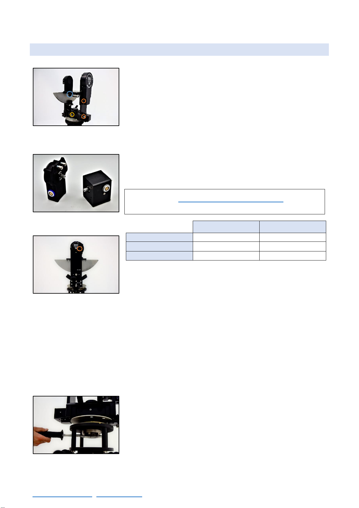
2.3 FULCRUM
The fulcrum is where the crane arm pivots in pan and tilt axes.
The fulcrum has encoders on the right side connected to the
Electronic box. Those encoders are linked to the fulcrum by belts and
inform the E.B. regarding any change in the position of the arm. That
information is used to display data in the portable display and to
perform functions as the Arc compensation or the motion generator
among other functions.
Both encoders give the same kind of signal and have the same
pinout. For troubleshooting they can be swapped to check if the
signal in the electronic box is received. The cables for the encoder
also have the same pinout but different color. The differences are the
housing and the color code of the connector (blue for tilt and grey for
pan).
There is only one way to mount the arm into the fulcrum since one
side is wider than the other. To lock the arm into the fulcrum, there
are two locking points under the arm support point in the fulcrum (C
in fig.02.17) where two knobs or two screws (M8x25mm) lockthe arm
depending on the model of the crane.
On the left side of the fulcrum there are two brake screws (fig.02.19). The brakes are not blockers:
when they are used, the crane is just hold in place by friction pads and it can be moved if the force
applied to move it is stronger than the friction of the pads. There is a slot for a M10 Allen key to
operate the PAN brakes and the TILT on the Scorpio 10’. On the Scorpio 17’ and the Scorpio 23’L
there is a handwheel to operate the TILT brake. If the crane needs to be blocked, always use straps
to lock it instead of these brakes.
On top of the brakes side, next to the pivot axis there is the screw for the tilt friction (A in fig.02.19).
If the user wants to adjust the friction on the tilt axis this screw can be tight to stiffen the tilt movement
or loosen to make it softer. The pan axis adjustment can be done in
the bottom part of the fulcrum (B in fig.02.17).
The fulcrum has a Mitchell mount so the cranes arms can be
mounted either in their own dolly or any other dolly or support with a
Mitchell mount on it. The support must be able to hold the arm in its
maximum payload.
Commercial references for
encoder belts:
Pan belt
Tilt belt
Scorpio 10’
5T2.5 540
5T2.5 540
Scorpio 17’
5T2.5 600
5T2.5 540
Scorpio 23’L
5T2.5 600
5T2.5 540
Note: in the chapter 6.4.1.2: Encoder belts there are
instructions on how to access and change the encoder belts.
02.17 Fulcrum.
A–Encoder connectors.
B–Pan fluid.
C–Arm locking point.
02.18 Tilt and Pan encoders.
02.19 Fulcrum brakes side.
A–Tilt fluid.
02.20 Fulcrum’s Mitchell mount.

SCORPIO LIGHT SERIES 10’/17’/23’L - PARTS AND COMPONENTS DESCRIPTION - Telescopic arm
Version 1.04 May 26, 2022
18
2.4 TELESCOPIC ARM
The arms of the cranes are made upof one main arm and telescopic sections that extends or retracts
automatically controlled by an operator with the Hand Command. In this chapter we will focus on the
different parts build on the arm, securities, and the mechanic components on it.
The basic components of the telescopic arm are the counterweight carriage (light green), the
levelling head (blue) at the end of the telescopic sections, the electronic box (red) which controls the
system, the side protection bars (yellow) and the rear counterweight support on the back of the arm.
The arm is slipped into the fulcrum and then is locked from below
with two knobs or two screws(M8x25mm) depending on the crane
model. Once the arm is locked and empty, it will always be heavier on
the back part of it. The front strap must be always strapped once it is
assembled (fig.02.22b), and it is highly recommended to strap the
back part of the arm to ensure it is safely stored.
The arm of the cranes consists in different aluminum sections but
there is always one fix (called Main Arm) which supports the other
telescopic sections. The telescopic sections are locked between them
with a safety pin (D10x35mm) to prevent them to extend while
transporting the arm (fig.02.22).
2.4.1 MAIN ARM
The Main section is the fix part that holds the rest of the components detailed before. Underneath
of it there are four support legs to rest the arm on them if is not assembled. Under the main arm there
is also the Electronic box (E.B.). It slides from any side of the arm and it is locked with four knobs
(M5x16mm). It controls the arm motor and manages all the interaction with the user and the rest of
the components on the arm.
The counterweights support is attached to the counterweight
carriage with two nuts (19mm). This counterweight carriage is used
to balance the telescopic range of the arm. The function of this
support is detailed in the chapter 3.4 Balance.
02.22 Telescopic sections locking pin.
02.23 Counterweight carriage attached.
Note: At this point, with the arm positioned on the fulcrum
with no payload, the arm will be BACK HEAVY. DO NOT
REMOVE THE FRONT STRAP WITHOUT BALANCING IT.
02.21 Scorpio 10’ Arm retracted with color coded parts.
02.22b Front strap point.
SCORPIO LIGHT SERIES 10’/17’/23’L - PARTS AND COMPONENTS DESCRIPTION - Telescopic arm
Version 1.04 May 26, 2022
SERVICEVISION BIS SL
Ríos Rosas, 20 · 08940 CORNELLA DE LLOBREGAT (Barcelona) Spain · Tel. 34 93 223 86 30 · Fax 34 93 223 86 31 19
comercial@servicevision.es · www.servicevision.es
Inside the back part of the main arm there is the arm motor. This motor transmits the movement to
the first section belt using an internal belt and pulleys. The first section belt is attached to the first
section (fig.02.24) and to the counterweight carriage. When the motor moves the belt, the first section
telescopes in one direction and the counterweight carriage moves on the opposite direction in order
to keep the arm balanced.
Commercial reference for internal motor belt:
The motor for the Scorpio 17’ and the Scorpio 23’L is the same but
the motor for the Scorpio 10’ is different. There is a detection system
inside the Electronic Box to identify which kind of motor is connected.
It is possible swap the electronic box from one crane to another by
making some internal adjustments (see chapter Replacement of the
Electronic box).
The range of movement of these motors is limited by software to the
length of the arm but the system does not know where to start that
range. In order to know where the limits of movement are, the Scorpio
cranes have two magnetic sensors to determinate the retracted
physical limit andthe extended physical limit of the arm. The extended
magnetic limit (fig.02.25) detects the magnet on the counterweight
carriage (fig.02.26) oncethe carriage gets close tothe limit on the rear
part of the arm. The retracted limit detects a magnet attached to the
right side of the first section (fig.02.34) when the first section gets
close to the rear part of the arm. These magnetic limits are located in
the rear part of the arm and are connected to the E.B. through the
motor connector. The sensors detect the magnetic field of the magnet
and determinates where the limits of the arm are. The detection of the
magnetic field of the magnet may vary depending on the speed of the
arm arriving to these sensors.
On the back part of the crane there is the rear counterweight support (fig.02.27) where weights can
be added in order to balance the crane. The function of this support is detailed in the chapter 3.4
Balance.
Scorpio 10’
For s/n 001 to s/n 090: T5 590
Rest of s/n: 600-5M-9
Scorpio 17’
For s/n 001 to s/n 003: T5 830
Rest of s/n: 835-5M-HT
Scorpio 23’L
For s/n 001 to s/n 007: T5 830
Rest of s/n: 835-5M-HT
Note: in the chapter 6.4.1.3 Main motor there are instructions
on how to access and change the motor and its belt.
02.24 Attachment plate to the first
section.
02.25 Extended magnetic limit.
02.26 Carriage magnet.
02.27 Rear counterweight support.
SCORPIO LIGHT SERIES 10’/17’/23’L - PARTS AND COMPONENTS DESCRIPTION - Telescopic arm
Version 1.04 May 26, 2022
20
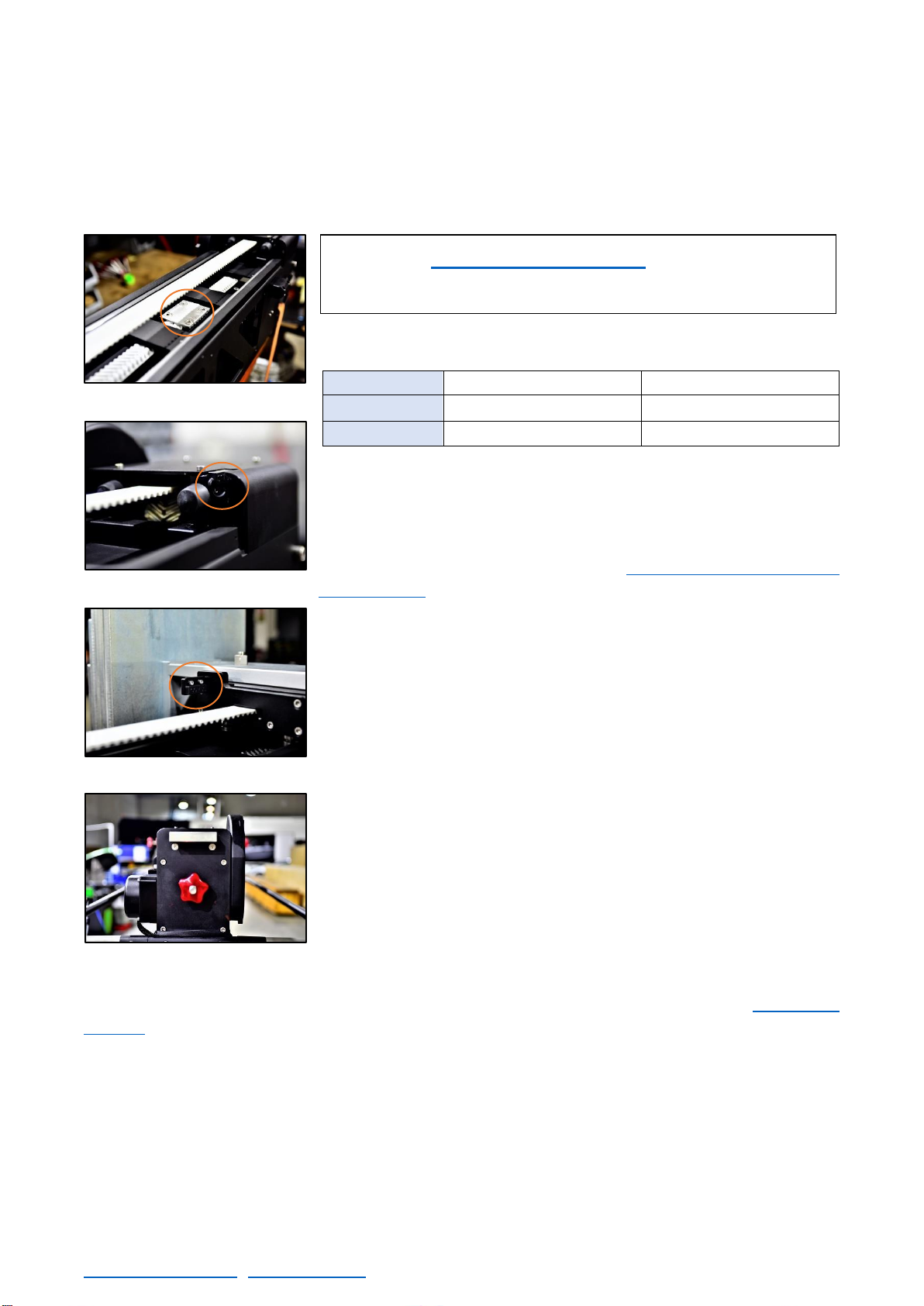
2.4.2 OPERATION BARS
There are two pivots in both sides of the main arm, two in the front
part of the arm and two in the back. These pivots are used for fixing
the Protection bars (fig.02.28) to the crane. In these pivots is where
the screw that holds the side Protection bars are screwed (DIN912
M8x45mm). Notice that both side protection bars are equal. The hand
command bracket must be introduced into the side bar before
mounting it into the arm. There are sliding weights available to attach
on these protection sidebars.
When the column is fully lifted it is hard to operate the arm using the
protection bars. There is an accessory bar (fig.02.28b) for those
situations where the operation bars are too high to control the arm of
the crane.
02.28 Protection bars.
Note: The protection bars mark the area of movement of the
Telescopic counterweights, therefore NEVER get in between
the protection bars and the crane, there is a high risk of
squashing if the crane moves. These bars are used by the
operator to control the movement of the crane.
02.28b Lower operation bar
This manual suits for next models
3
Table of contents
Other Servicevision Camera Accessories manuals


Popular Camera Accessories manuals by other brands


Fantasea
Fantasea Remora Flash Operator's manual

Invacare
Invacare XPO110 Assembly, installation and operating instructions

Bioenno Power
Bioenno Power BLF-4820A manual

Johnson Controls
Johnson Controls Illusta PRO IBWT-P-ISWB-A quick start guide

LEOFOTO
LEOFOTO LH-25 user manual

Sanyo
Sanyo N-1U Cadnica Specifications


