T
e
ctive balanced XLR and 1/4''
ack
Im
edance Balanced >50kohm, Unbalanced>25 kohm
O
eratin
level +4dBu/-10dB
Max in
ut level +21dBu balanced and unbalanced
CMRR T
icall
>55dB at 1KH
T
e XLR and 1/4''
ack
Im
edance Balanced 60ohm, Unbalanced 30 ohm
Max out
ut level >+21 dBu
T
e 1/4''
ack
Im
edance 2 k ohm
Max in
ut level >+21 dBu
T
e 1/4''
ack
Im
edance >10k ohm
Max out
ut level >+24 dBu
Bandwidth 20Hz to 20kHz, +0/-0.5dB
Noise >-90dBu, unwei
hted, 22Hz to 22kH
<0.01% T
ical at +4dBu, 1 kHz, unit
ai
<0.04% T
ical at +20 dBu, 1kHz, unit
ai
IMD <0.01% T
ical SMPTE
Crosstalk <-100dB, 22Hz to 22kH
T
e Smart Ratio control Ex
ander
Threshold variable
OFF to +15dB
Ratio variable
1:1.2 to 1:8
T
e Smart Knee control Com
ressor
Threshold variable
-40dB to +20dB
Ratio variable
1:1 to ∞:1
Threshold Characteristic variable
Smart Knee control
Mnual Attack Time variable91ms to 150 ms
uto Attack Time T
ical 15 ms at 10dB, 5ms at 20dB, 3ms at 30dB
uto Release Time
ro
ram de
endent, t
ical 125 dB/
Out
ut Level variable
+20dB to +20dB
T
e Smart Gain control Peak Limiter
Threshold variable
0 to OFF
+22 dBu
Ratio ∞:1
Sta
e 1 Limiter T
eCi
e
ttack Time ''zero''
Release Time ''zero''
Sta
e 2Limiter T
e Pro
ram Limiter
ttack
ro
ram de
endent, t
,<5ms
Release
ro
ram de
endent, t
,20dB/s
SMART Enable the "smart knee control" characteristics
SC FILTER
llow for fre
uenc
de
endent
rocessin
Enable th automatic and
ro
ram de
enden
settin
of the Attack/Release times,
disen
a
in
the manual Attack/Release controls
I/O Mete
Switches between in
ut and out
ut for level mete
BYPASS B
ass switch
Chan
es the internal reference level from
+4dBu to -10dBu
Linkin
both channels for stereo o
eration
Channel1 becomes master
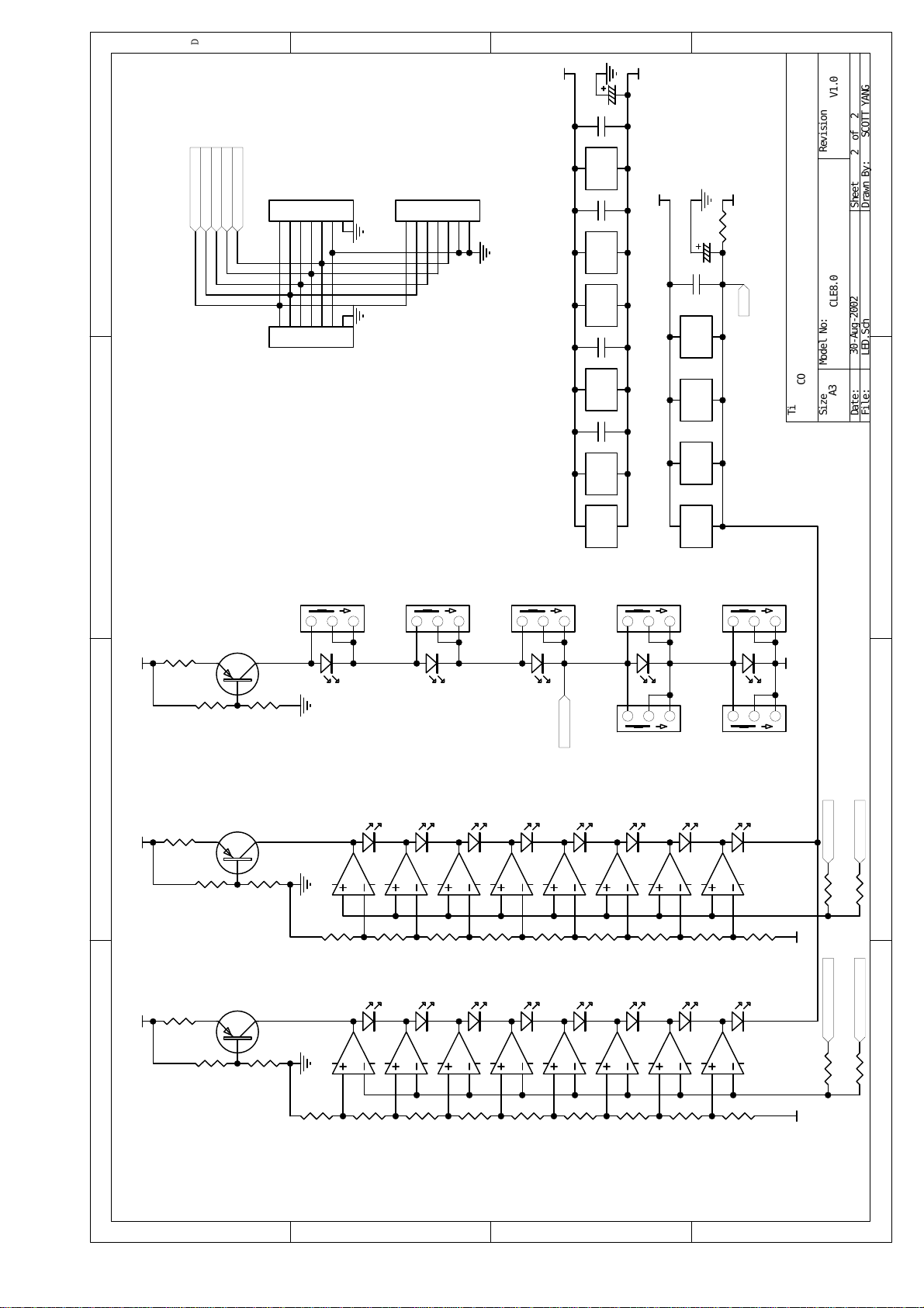
GAIN REDUCTION 8-Se
ment LED dis
la
:1/3/6/10/15/20/25/30d
INPUT/OUTPUT LEVEL 8-Se
ment LED dis
la
:-24/-18/-12/-6/0/+6/+12/+18d
Ex
ander/Gfate Threshold 2LED for under ";+" and above "-"
Com
ressor Threshold 3 LED for under"+", interactive"0", and above "-
Peak limiter Threshold 1 LED for indication of limiter function
Function Switches LED indicator for each
USA/Canada ~120VAC,60H
UK/Australia ~240VAC,50H
Euro
e ~230VAC,50H
General Ex
ort Model ~100-120VAC, ~200-240VAC, 50
100-120VAC: 630mA
SLOW-BLOW
200-240VAC:315mA
SLOW-BLOW
Power Consum
tion 40 watts
Mains Connection Standard IEC rece
tacle
Dimension
W*D*H
485.0*233.0*90.0mm
Net Wei
ht 5.2 K
THD
Mains Voltages
Fuse
Physical
Power Supply
Indicators
LINK
OPERATING LEVEL
AUTO
Function Switches
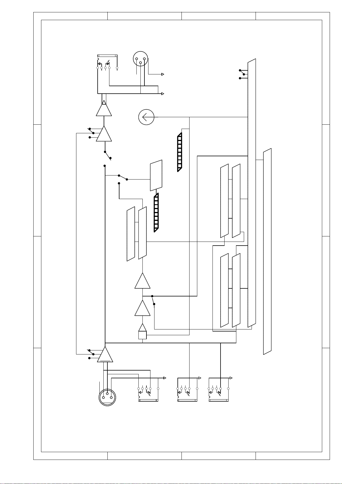
Peak Limiter Section
Compresser Section
Expander/Gate Section
System Specifications
Return
Send
Output Section
Input Section