SLI POLY User manual
Operation Manual
Ver 24-01
Flexible Wavelength Selector
POLY

www.spectrolightinc.com
1. Introduction
1.1 Poly-RED
1.2 Poly-BLUE
2. Installation
2.1 Main components
2.2 Product overview
2.3 Software installation
2.4 Product installation
3. Operation (Wavelength mode)
3.1 Setting the center wavelength and bandwidth
3.2 Scanning across a certain wavelength range
3.3 Setting or editing the preset wavelength and bandwidth
3.4 When to use “BLANK”
4. Operation (Raman mode, optional)
4.1 Setting the center Raman shift and bandwidth
4.2 Scanning across a certain Raman shift range
4.3 Setting or editing the preset Raman shift and bandwidth
5. Trouble shooting
5.1 Device connection error
5.2 Device not working
6. Software development kit
6.1 Poly DLL Manual
6.2 Overall Poly control flow using SDK via Labview
7. Accessories guide
7.1 Accessories overview
7.2 Input accessories
7.3 Output accessories
8. Product selection guide
8.1 Wavelength selection guide
8.2 Full specifications
9. Scheme drawing - Poly-RED, Poly-BLUE
TABLE OF CONTENTS

www.spectrolightinc.com
The Flexible Wavelength Selector Poly (Poly-RED, Poly-BLUE) is a tunable bandpass filter which utilizes TwinFilm™
technology to provide a simple software control (scanning or setting) of the center wavelength and the bandwidth
via a USB communication. With both high (10-6) out of band rejection and excellent (>75%) transmission, the Flexible
Wavelength Selector (FWS) is a simple, turnkey solution for various applications that require specific wavelength
excitation and detection throughout the extended wideband spectrum (255 – 1700 nm). Poly is simple to integrate
with broadband light sources, cameras, and other instruments, resulting in Tunable light source and Hyperspectral
imaging application.
Poly is divided into the Poly-RED and the Poly-BLUE product lines, depending on the bandwidth control function.
The Poly-RED model can control center wavelength and bandwidth (FWHM) simultaneously. For the Poly-BLUE
model, only the center wavelength can be controlled with the fixed bandwidth of 20 nm (nominal).
Also, Poly has different product lineups depending on input beam size. The Poly-A5 models have beam aperture of
5 mm and is mainly used in case of broadband light source with small beam size such as supercontinuum lasers.
For large beam sizes such as LEDs and lamps the Poly-A10 model with an aperture size of 10 mm is recommended.
1. Introduction
High precision
Accurate bandwidth control
Adjustable FWHM
2 - 15 nm (nominal)
1. Broadband spectral range
2. High damage threshold
3. High throughput
4. Diverse aperture size
5. Great out of band blocking
Appropriate precision
Improved output power
Fixed FWHM
20 nm (nominal)
Poly-RED Common Specifications Poly-BLUE
255 - 1700 nm
< 2 MW/cm2(CW)
> 75 %
5 / 10 mm
OD 12 at tuning range
OD 6 out of tuning range

www.spectrolightinc.com
1.1 Poly-RED
Each Poly-RED model can cover a different spectral range. The bandwidth of Poly-RED can be adjusted from 2 to
15 nm (nominal). The exact adjustable bandwidth is different for each model. Please refer to the table below for
more details on the tuning range. For the Custom model, you can configure the product by selecting the type of
filter you want according to the user's purpose from the wavelength selection table below.
* Center Wavelength tuning range can vary by a few nanometers depending on the product.
Minimum step size of center wavelength : 1 nm
Step size of bandwidth (FWHM) : 1 nm
Aperture size : 5 mm (model : Poly-A5) / 10 mm (model : Poly-A10)
1. Introduction
Bandwidth selection range according to spectral range
Poly-RED-UV
Poly-RED-VIS
Poly-RED-IR
Poly-RED-SWIR
Poly-RED-Custom
280 - 390
430 - 790
775 - 1150
1140 - 1700
Custom range
Model name Spectral range (nm)
255 - 700
701 - 890
891 - 1500
1475 - 1700
2
3
5
7
15
15
15
13
Spectral range (nm) Minimum bandwidth (nm) Maximum bandwidth (nm)
255 - 290
3 - 15 5 - 15 7 - 13
280 - 310
310 - 350
348 - 390
385 - 435
430 - 490
485 - 550
545 - 620
615 - 700
690 - 790
775 - 890
880 - 1015
1000 - 1150
1140 - 1310
1300 - 1500
1475 - 1700
Poly-RED-UV
Poly-RED-VIS
Poly-RED-IR
Poly-RED-SWIR
Poly-RED-Custom
CWL
FWHM
Up to 9 in one device
2 - 15

www.spectrolightinc.com
1.2 Poly-BLUE
Each Poly-BLUE model can also cover a different spectral range with bandwidth fixed at 20 nm (nominal). Please
refer to the table below for more details on the tuning range. For the Custom model, you can configure the product
by selecting the type of filter you want according to the user's purpose from the wavelength selection table below.
* Center Wavelength tuning range can vary by a few nanometers depending on the product.
Minimum step size of center wavelength: 1 nm
Bandwidth (FWHM) Fixed: 20 nm (nominal)
Aperture size: 5 mm (model : Poly-A5) / 10 mm (model : Poly-A10)
1. Introduction
Poly-BLUE-UV
Poly-BLUE-VIS
Poly-BLUE-IR
Poly-BLUE-SWIR
Poly-BLUE-Custom
280 - 390
430 - 790
775 - 1150
1140 - 1700
Custom range
Model name Spectral range (nm)
255 - 290
280 - 310
310 - 350
348 - 390
385 - 435
430 - 490
485 - 550
545 - 620
615 - 700
690 - 790
775 - 890
880 - 1015
1000 - 1150
1140 - 1310
1300 - 1500
1475 - 1700
Poly-BLUE-UV
Poly-BLUE-VIS
Poly-BLUE-IR
Poly-BLUE-SWIR
Poly-BLUE-Custom
CWL
FWHM
Up to 9 in one device
20 (nominal)
www.spectrolightinc.com
2. Installation
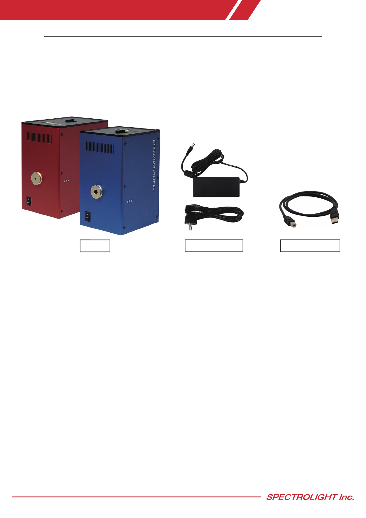
2.1 Main components:
A. Poly B. Power adapter C. USB cable (A-B)
A. Poly : Main device (Software controlled tunable bandpass filter)
B. Power adapter : Power supply cable and power adapter for the Poly
(Power plug types are provided in accordance with the country specified in the order)
C. USB cable (A-B) : A to B type USB cable for connecting the Poly to operating PC
* WARNING : When relocating the Poly, ensure that the locking switch is in the ‘LOCK’ position for
safety reasons. Change the locking switch to the ‘UNLOCK’ position when the device is in an idle
state and is ready for use.

www.spectrolightinc.com
2. Installation
A. USB port
B. Power port C. Power switch
D. Locking switch
2.2 Product overview
A. USB port : Port for connecting the USB cable from the device to the operating PC/Tablet
B. Power port : Port for connecting power supply cable
C. Power switch : Power switch for turning the device ON and OFF
D. Locking switch : Locking switch to LOCK and UNLOCK the device

www.spectrolightinc.com
2.3 Software installation
Minimum PC Requirements : Any PC or Windows Based Tablet (Windows 7 or higher).
If Windows is working properly, this software will also work properly.
– Please do not connect the device before installing the software.
1. Please go to our website www.spectrolightinc.com to download the installer file.
Software location -
Products » Tunable bandpass filters » Poly » Resources » Software
a. Download the software file from the website.
b. Unzip the zip file.
Inside the zip file there should be 4 folders -
1. User_software
2. SDK
3. C#_example
4. Labview_example
The software installer file is located in the 1. User_software folder.
a. Double click Setup.exe
b. Follow the guidelines
2. Install the Poly software on a PC/Tablet running Microsoft Windows (7 or later).
3. Copy the calibration file (.ism2 extension file) provided by the distributor/manufacturer to the default
location
→C:\SLI2\POLY2
If the calibration file is not provided to you, please contact us by email at [email protected]
This file should be copied to your installation directory.
Please select this file and click on Apply after you run the Poly software.
2. Installation
DO NOT TURN ON THE DEVICE UNTIL YOU READ AND UNDERSTAND THIS INSTALLATION GUIDE.
TURNING ON THE DEVICE WITHOUT SETTING THE LOCKING SWITCH TO THE ‘UNLOCK’ POSITION
WILL LEAD TO CRITICAL DAMAGE.

www.spectrolightinc.com
2.4 Product installation
1. WARNING : When relocating the Poly, ensure that the locking switch is in the ‘LOCK’ position for safety
reasons. Change the locking switch to the ‘UNLOCK’ position when the device is in an idle state and is
ready for use.
2. Figure below shows the ‘LOCK’ and Figure 2 below shows ‘UNLOCK’ positions, respectively.
LOCK UNLOCK
3. When the user first receives the product, the locking switch should be in the 'LOCK' position. For operation
of the device locking switch must be changed to the 'UNLOCK' position.
4. Plug the USB cable (A-B) into Poly, then connect the other end to the operating Computer/Tablet.
5. Plug the power supply cable into the power port of Poly, located just beside the USB port.
Connect the power supply to a properly grounded outlet.
6. Find the power switch just beside the power port. Turn ON the device.
7. To start operating the device, locate the software icon on your Desktop, then execute the installed software.
The software will ask for a calibration file appropriate for your device.
Select the calibration file that matches the device serial number and click the ‘Apply’ button.
(calibration file must be in the same folder as the software file)
2. Installation
www.spectrolightinc.com
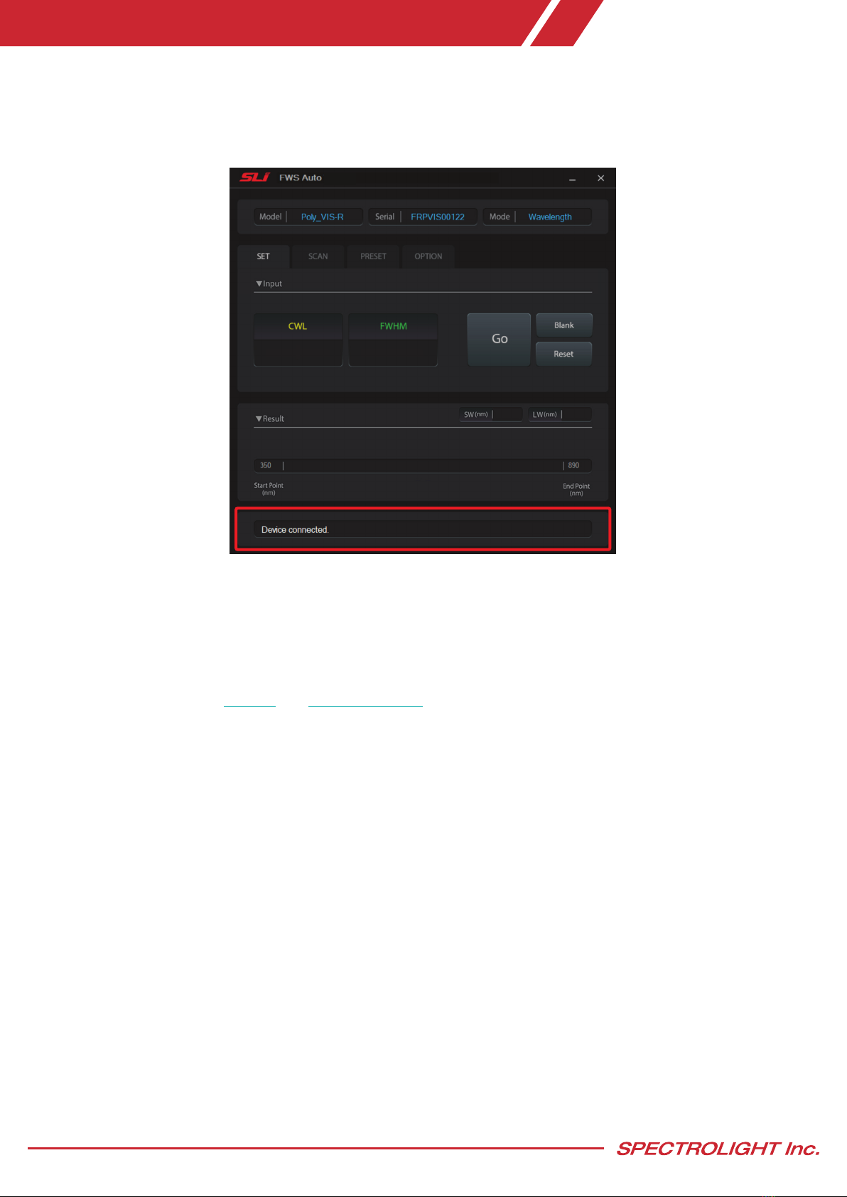
8. If there are no problems with the instrument and calibration file, the software and device should connect
promptly. If the connection is successful, the software interface should display the message 'Device connected'
at the bottom of the screen. The device is now ready to use.
9. Properly align the light source with the specified input port to direct the emitted light towards the designated
output port. Ensure that the orientation of the input beam follows the indicated arrow direction.
*For optimal performance of the product, it is recommended that the incident light be collimated.
It is possible to couple Poly with different types of broadband sources, such as supercontinuum lasers, laser
driven light sources, and fiber output broadband lamp sources. We provide connecting adapters for each type.
You can also refer to our website and YouTube channel for details about these adapters.
You can contact our support team at [email protected]
2. Installation
www.spectrolightinc.com
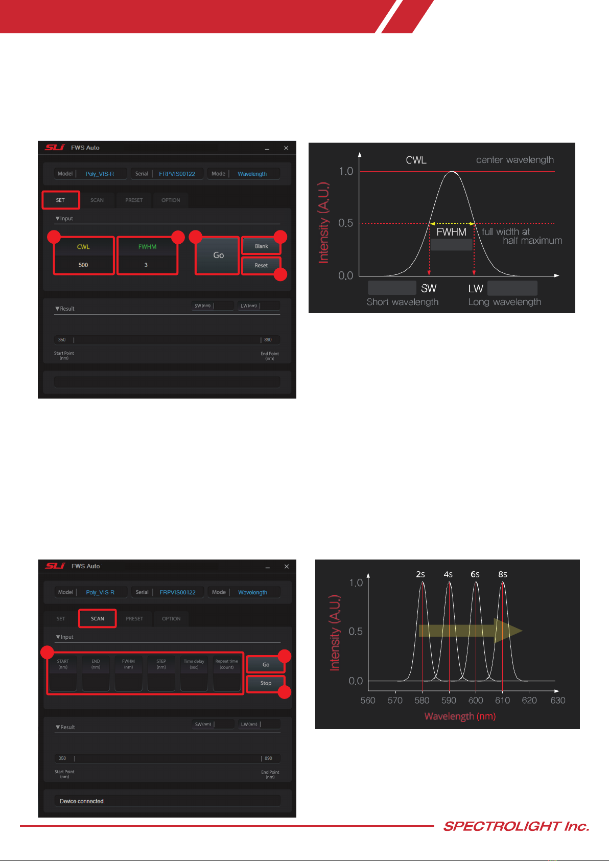
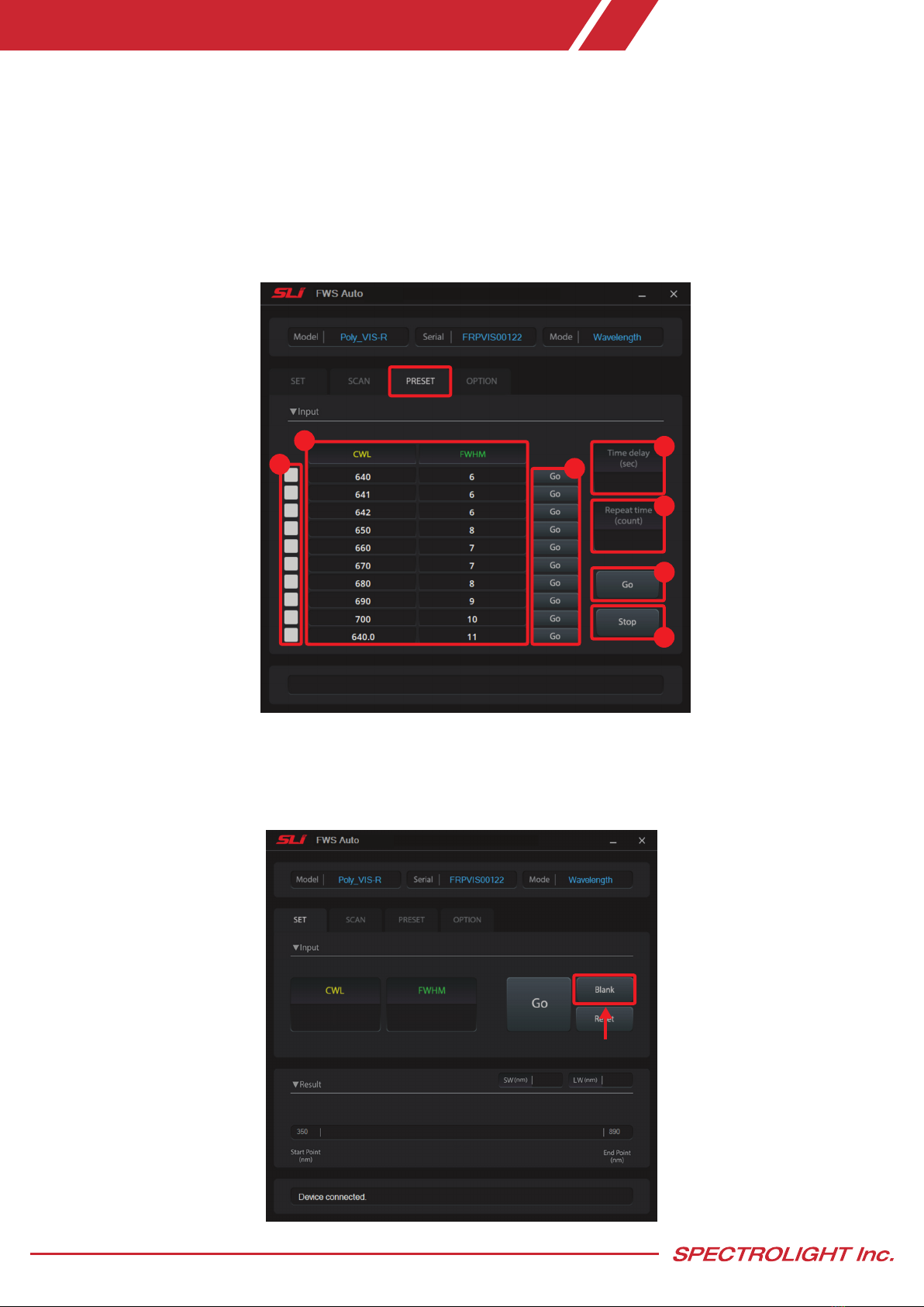
3.1 Setting the center wavelength and bandwidth
1. CWL (nm) : enter the desired CWL (center wavelength)
2. FWHM (nm) : enter the desired FWHM (full-width at half maximum)
3. Go : click to start wavelength tuning
4. Blank : click to set blank mode
5. Reset : click to reset filter
500
3.0
501.5498.5
3.2 Scanning across a certain wavelength range
1. Enter the following values
- START (nm) : wavelength to start scanning
-END (nm) : wavelength to end scanning
-FWHM (nm) : bandwidth during the scanning
-STEP (nm) : step size of the scan in nm
-Time delay (sec) : set the time delay between each individual wavelength steps
- Repeat time (count) : number of full scans
2. Go : click to start scanning
3. Stop : click to stop scanning
3. Operation (Wavelength mode)
580 610 510 210
1234
5
12
3
www.spectrolightinc.com
3. Operation (Wavelength mode)
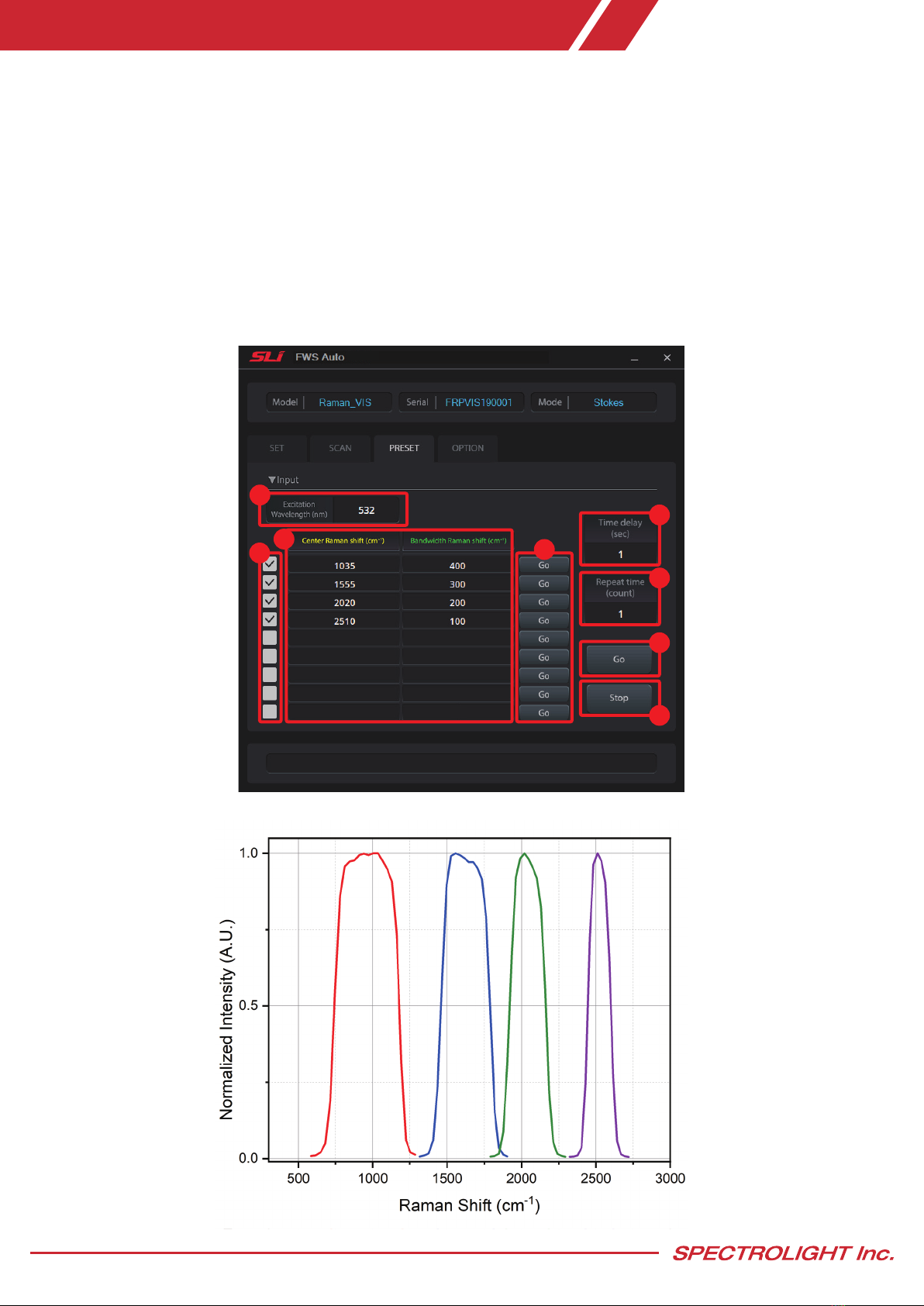
3.3 Setting or editing the preset wavelength and bandwidth
- In the PRESET tab, you can set your frequently used wavelength and bandwidth for easy access.
1. CWL, FWHM (nm) : enter the desired CWL and FWHM value
2. Preset Selection : select the presets that is to be scanned
3. Go (individual) : click to scan individual presets
4. Time delay (sec) : set the time delay between each individual presets
5. Repeat time (count) : number of full scans
6. Go : click to scan all selected presets
7. Stop : click to stop scanning
3.4 When to use blank mode
-Blank mode is the state wherein no filters are positioned in the pathway of the input light source.
This way, it is possible to check the alignment of the input light source.
1
23
4
5
6
7
www.spectrolightinc.com
4. Operation (Raman mode, optional)
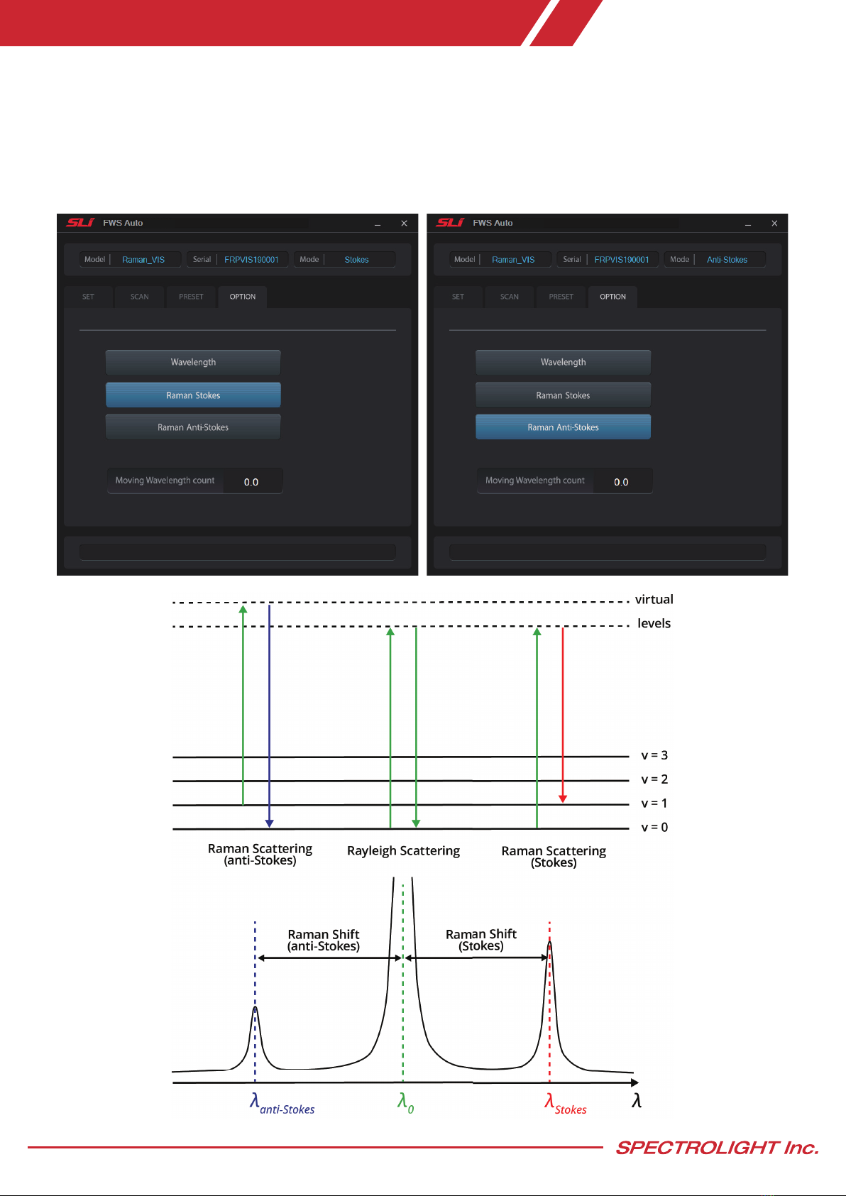
4.1 Raman mode (Optional function)
Customers who purchase the Raman model of Poly-RED can use Raman mode to detect specific Raman band for
imaging. The Raman model can select two modes (Stokes, Anti-stokes) in the options tab.
*NOTE : The Raman model is only available for the Poly-RED model.
www.spectrolightinc.com
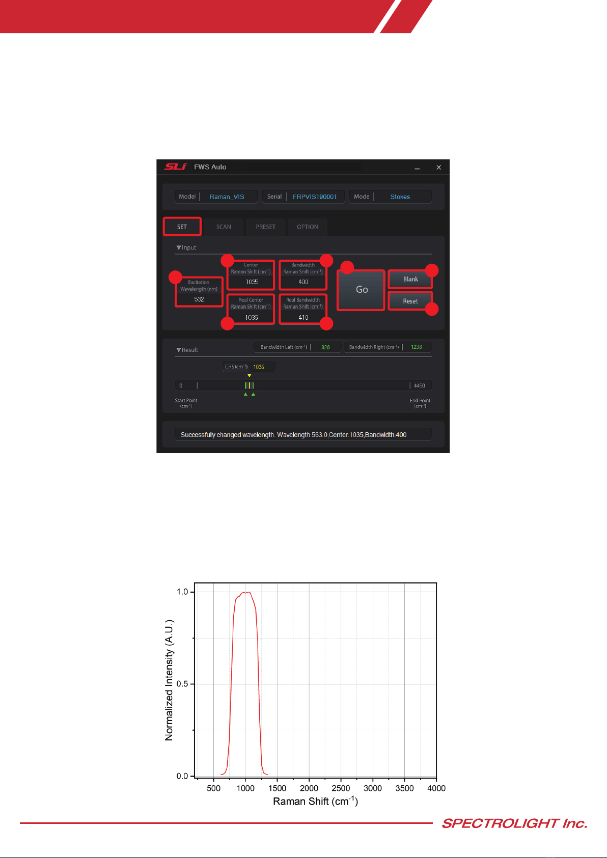
4.2 Setting the center Raman shift and bandwidth
- Since Stokes Raman shift and anti-stokes Raman shift represent the same information as mirror images, this
manual mainly explains Stokes Raman shift.
- FWS operates on Wavelength Base, and in order to use it in Raman mode, it operates by converting wavelength
to wavenumber. Because the wavenumber is inversely proportional to its wavelength, the specified wavenumber
value may not be the exact wavelength at which the Poly can move. Therefore, the Poly sets the wavelength
value closest to the user-specified wavenumber.
4. Operation (Raman mode, optional)
1. Excitation Wavelength (nm) : enter the desired Raman Excitation Wavelength
2. Center Raman Shift (cm-1) : enter the desired Center of Raman shift
3. Bandwidth Raman Shift (cm-1) : enter the desired Bandwidth of Raman shift
4. Real Center Raman Shift (cm-1): indicates the actu al moved value of Raman shift wavelength
5. Real Bandwidth Raman Shift (cm-1) : indicates the actual moved value of Raman shift bandwidth
6. Go : click to start Raman shift tuning
7. Blank : click to set blank mode
8. Reset : click to reset filter
1
23
4 5
67
8
www.spectrolightinc.com
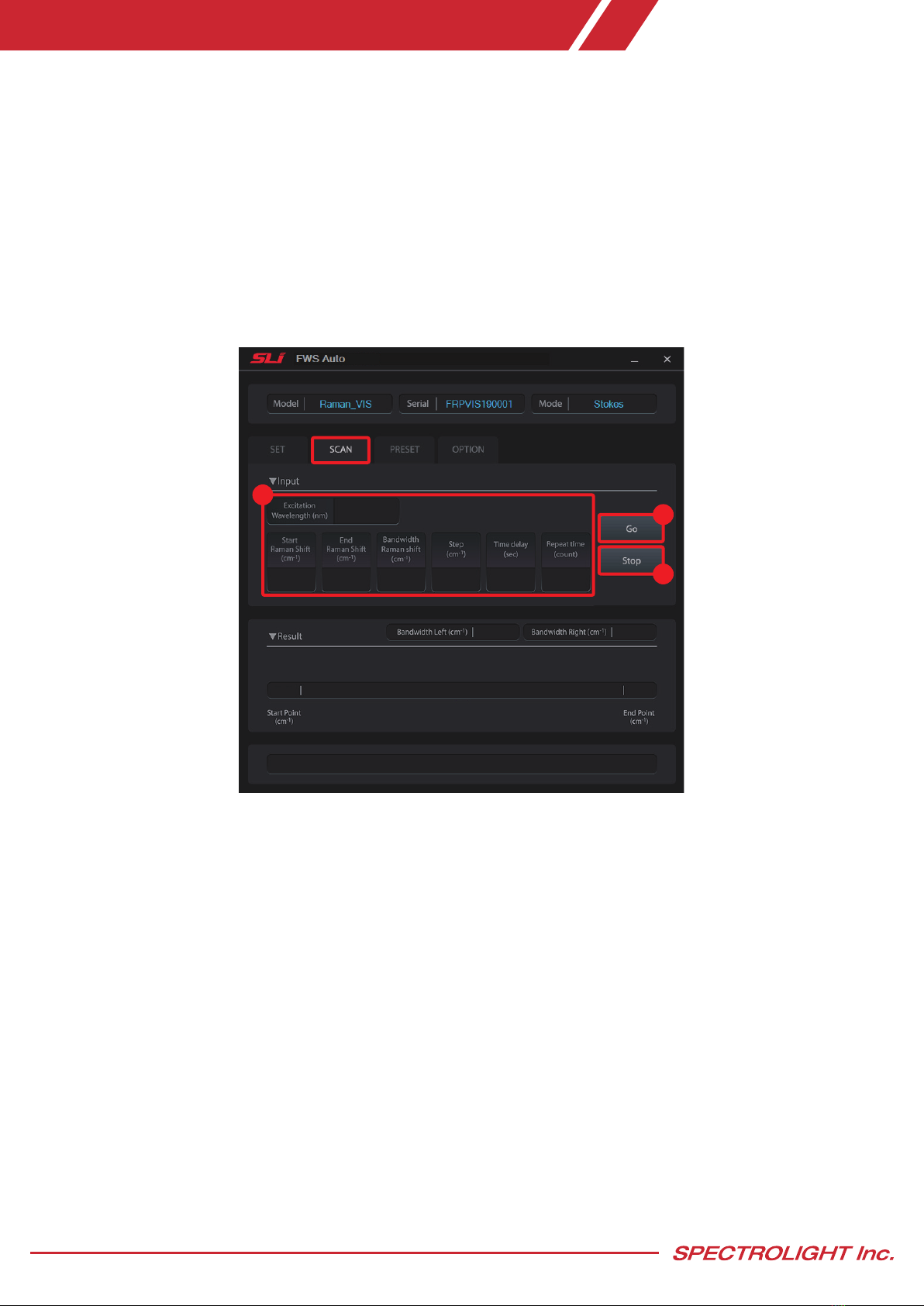
4.3 Scanning across a certain Raman shift range
1. Enter the following
- Excitation Wavelength (nm) : enter the Raman Excitation Wavelength
- Start Raman Shift (cm-1) : Raman shift to start scanning
-End Raman Shift (cm-1) : Raman shift to end scanning
-Bandwidth Raman Shift (cm-1) : bandwidth during the scanning
-Step (cm-1) : step size of the scan in wavenumber
-Time delay (sec) : set the time delay between each individual wavelength steps
- Repeat time (count) : number of full scans
2. Go : click to start scanning
3. Stop : click to stop scanning
*Note : Although the Poly has calibration data at intervals of 0.2 nm as the wavelength base, there may be instances
where a specific wavenumber does not have a corresponding value because the wavenumber is inversely proportional
to its wavelength. Consequently, scanning with a constant wavenumber step may not yield optimal results.
For scanning of a specific Raman band, it is recommended to use Preset mode to scan a specific band.
4. Operation (Raman mode, optional)
1
2
3
www.spectrolightinc.com
4.4 Setting or editing the preset Raman shift and bandwidth
- In the PRESET tab, you can set your frequently used center Raman shift and bandwidth for easy access.
1. Excitation Wavelength (nm) : enter the Raman Excitation Wavelength.
2. Preset Selection : select the desired presets to be scanned
3. Center Raman shift, Bandwidth Raman shift (cm-1) : enter the desired Center Raman shift and Bandwidth
Raman shift
4. Go (individual) : click to scan individual presets
5. Time delay (sec) : set the time delay between each individual presets
6. Repeat time (count) : amount of times selected presets are scanned
7. Go : click to scan all selected presets
8. Stop : click to stop scanning
4. Operation (Raman mode, optional)
1
234
5
6
7
8

www.spectrolightinc.com
5. Trouble shooting
5.1 Device connection error
- If the device and software cannot be properly connected, check whether the communication driver appears
properly in Device Manager. If it is a problem with the communication driver, install the latest FTDI USB
driver suitable for your OS from the following website - https://ftdichip.com/drivers/
5.2 Device not working
- Even though the device and PC are properly connected, if the device does not operate, check the locking
switch position. The locking switch must be changed to the 'UNLOCK' position to operate.

www.spectrolightinc.com
6. Software development kit
6.1 Poly DLL Manual
SDK file is based on ".NET Framework 3.0"
Namespace: ISM_Device
The class : ClassPoly.
Python supports the "Python.NET" package for the Python programmers.
Or you can check another way of this in the link below.
https://github.com/pythonnet/pythonnet
Labview also support the way to call .NET dll, please refer to a simple example file.
For the overall function flow, refer to the labview example description.
A. Function return value
DLL internal declaration
enumPolymsg:int
{
MSG_NO_ERROR = 0,
MSG_DEVICE_SEARCHING = 1,
MSG_CONNECTION_OK = 2,
MSG_SET_WAVE_OK =3,
MSG_DEVICE_INIT = 4,
MSG_DEVICE_BUSY = 5,
MSG_DEVICE_READY = 6,
MSG_DEVICE_CLOSE_PORT = 10,
ERR_DEVICE_NOT_FOUND = -1,
ERR_DEVICE_FILE_NOT_FOUND = -2,
ERR_DEVICE_FILE_ERROR = -3,
ERR_DEVICE_NOT_READY = -4,
ERR_DEVICE = -5,
ERR_DEVICE_ERROR_MODEL_NO = -6,
ERR_DEVICE_ERROR_SERIAL_NO = -7,
ERR_DEVICE_ERROR_WAVE_RANGE = -8,
ERR_DEVICE_NOTCONNECTED = -9,
ERR_COMM_CONN_ERROR = -11,
ERR_COMM_CONN_LOST = -12,
ERR_COMM_TIMEOUT = -13,
ERR_COMM_ERROR = -14,
ERR_NOT_FOUND_WAVE = -21,
ERR_SET_WAVE_ERROR = -22,
}

www.spectrolightinc.com
MSG_NO_ERROR = The command has been executed properly.
MSG_DEVICE_SEARCHING = Searching for device.
MSG_CONNECTION_OK = Device is connected.
MSG_SET_WAVE_OK = Successfully changed CWL and FWHM.
MSG_DEVICE_INIT = Device is initializing.
MSG_DEVICE_BUSY = Device is busy.
MSG_DEVICE_READY = Device is ready.
MSG_DEVICE_CLOSE_PORT = Device is not ready.
ERR_DEVICE_NOT_FOUND = Device not found.
ERR_DEVICE_FILE_NOT_FOUND = Calibration file not found.
ERR_DEVICE_FILE_ERROR = Calibration file error.
ERR_DEVICE_NOT_READY = Device is busy.
ERR_DEVICE = Communication error.
ERR_DEVICE_ERROR_MODEL_NO = Calibration file and model number doesn’t match.
ERR_DEVICE_ERROR_SERIAL_NO = Calibration file and serial number doesn’t match.
ERR_DEVICE_ERROR_WAVE_RANGE = Calibration file and wavelength range doesn’t match.
ERR_DEVICE_NOTCONNECTED = Device is not connected.
ERR_COMM_CONN_ERROR = Communication error.
ERR_COMM_CONN_LOST = Device disconnected.
ERR_COMM_TIMEOUT = Communication timeout.
ERR_COMM_ERROR = Communication command internal error.
ERR_NOT_FOUND_WAVE = Wavelength out of range.
ERR_SET_WAVE_ERROR = Returning of error for GetCurrentWavelengthdue to absence of Set wavelength
because of SetWavelengthcommand error
6. Software development kit

www.spectrolightinc.com
B. Poly commands
1. int PolyConnect(string path);
-Parameters
path : Path and location of calibration file
-Return Value
MSG_NO_ERROR
ERR_COMM_ERROR
ERR_DEVICE_ERROR_MODEL_NO
ERR_DEVICE_ERROR_SERIAL_NO
ERR_DEVICE_ERROR_WAVE_RANGE
ERR_DEVICE_NOT_FOUND
ERR_DEVICE_FILE_NOT_FOUND
ERR_DEVICE_FILE_ERROR
-Remark
Use the calibration file to activate the port then connect
2. intDisconnect();
-Parameters
-Return Value
MSG_DEVICE_CLOSE_PORT
ERR_COMM_TIMEOUT
ERR_COMM_ERROR
-Remark
Stop communication and close port.
3. intGetDeviceStatus();
-Parameters
-Return Value
MSG_DEVICE_INIT
MSG_DEVICE_BUSY
MSG_DEVICE_READY
ERR_COMM_CONN_LOST
ERR_DEVICE_NOTCONNECTED
-Remark
Read the current status of the device.
4. bool GetDeviceEnabled();
-Parameters
-Return Value
True : Port is openand device is connected.
False : Port is closedor device is not connected.
-Remark
Check the connection status of the device.
5. string GetComPortNumber();
-Parameters
-Return Value
COM port String return
-Remark
Read the connected COM port
6. Software development kit
This manual suits for next models
5
Table of contents
Popular Industrial Equipment manuals by other brands

Shaver
Shaver HD-10 Operator's manual

SCHUNK
SCHUNK SRM Series Assembly and operating manual

eta
eta HACK 130-200 Installation, configuration and maintenance

Simplex
Simplex 2120 General information

Power One
Power One Aurora Universal Industrial installation guide

BLOCK AND ROLL
BLOCK AND ROLL Multi Form 700 instruction manual


Arroyo Instruments
Arroyo Instruments LaserSource 4205 manual

Fröling
Fröling Screening screw 150 Installation and operating instructions

BIFFI
BIFFI ICON3000 Series Installation, operation and maintenance manual

Fireye
Fireye HEP-2-Z Series operating manual

DTI
DTI WINCO PSS12H2W/D Installation and operator's manual

Smartgen
Smartgen HGM9530 user manual