Linn LOUDSPEAKERS User manual

LOUDSPEAKERS
LINN

Revised Dec 97
Copyright © 1991-1997 by Linn Products Limited. All Rights Reserved.
Page2 Index
SECTION 6 - LOUDSPEAKERS
Contents: Page:
Introduction 3
Aktiv/Passive 3
GeneralSet-UpofLinnLoudspeakers 4
Cable 4
DriveUnits 4
Positioning 4
Stands 4
GeneralInformationaboutSpeakerUnits 5
DamagedUnits 5
Faulty Units 6
Faultfinding 7
Guidelinesforupdateandrepair
ChangingSpeakerUnits 10
SiliconeSealedTrebleUnits 11
Midrange / Bass units 13
Isobarik Bass Units 15
Gasket Sealed Units 16
Changing Components in the Sekrits 17
SealingSpeakers 19
SimpleSpeakerPhasingTest 20
Grilles:
NewSpeakerGrilles 21
FullLengthSpeakerGrilles 22
How to reduce the treble by 1dB 23
ConvertingfromPassivetoAktiv:
Kabers 24
Keilidhs 25
Tukans 28
Sekrits 29
Stands:
Replacing Faulty Keilidh Stand Insert 30
SpeakerStands 33
Modifying Helix / Nexus for Kustone Stand 33
Sekrit Speakers 35
LinnBrakit 37
Trebleupgradeto:
Index II Nexus II 39
HelixII 41
NexusIV 42
Kaber/1 43
ConvertIsobarikPassivetoexternalcrossover 44
LoudspeakerHistory 46
Louspeaker Specifications 55
Bi-wiringandBeyond 61
LoudspeakerAccessories 64

Copyright © 1991-1997 by Linn Products Limited. All Rights Reserved. Page3
Revised Dec 97
Index
LINN LOUDSPEAKERS
Loudspeakers are the final link in the hi fi chain. The challenge of making
loudspeakers perform properly is similar in many respects to getting the best
fromturntables. When aspeakerconvertssignalsintosoundwaves itinvolves
movementssimilarinscaletoastylusinarecordgrooveinaddition,ofcourse,
tomuch largermovements.
Toreproducemusicaccurately,thespeaker'sdriveunitmovements mustbevery
precise. Thetaskofspeakerengineering is essentiallyamechanicalone,whilst
at the same time requiring the highest quality of electrical components.
ISOBARIK
Linn's KELTIKloudspeakerhasthepatented'Isobarikequalpressure'system,
first used in the Linn Isobarik. Behind the visible bass speaker is another
mounted insidethe cabinet. With thissystem, the front speakerworks as if in
amuchbiggerenclosure.
PASSIVE PLAYBACK
With a passive loudspeaker, the signal from the amplifier is divided into three
frequency bands, (bass, mid and treble) by a passive filter built into the
loudspeakercabinet. Thisispoweredbythesignalitself,absorbingsomeofthe
amplifier power, and preventing the amplifier from accurately controlling the
loudspeaker.
Although the highest quality components are used in Linn loudspeakers, there
are several fundamental limits to the performance of a passive loudspeaker
system.
ACTIVE PLAYBACK
Anactivecrossoverfreestheloudspeakersystemfromtheselimits. Itaccurately
divides the signal from the preamplifier into three frequency bands, and feeds
each to its own power amplifier. The loudspeaker drive units are directly
controlledbythepoweramplifiers. Theelectroniccircuitryoftheactivecrossover
makes it possible to control the drive units in the AKTIV speaker precisely and
overanextendedfrequencyrange.
The combination of active crossover, high power amplifiers and advanced
loudspeakerdriveunitsintheKELTIK systemresultsinanextremelyaccurate,
musicalsystemwhichiscapableof playing music at realistic soundlevels.The
KELTIK is only available in Aktiv while all other LINN speakers (excluding
AV5110) can be used in Aktiv or Passive versions.
CABLE
Linn use 20 amp multistrand copper cable for optimum sound quality.
ASSEMBLY
Eachassemblerbuilds,testsandpacksacompletepairofspeakersatpurpose
designed work stations, to ensure that matching pairs of loudspeakers are
produced.
SERVICE MANUAL
This section contains important information on set-up and service of Linn
loudspeakers, thehistoryofeachloudspeakermodel, speakerfaultfindingand
repairguidestogetherwithspecifications.

Revised Dec 97
Copyright © 1991-1997 by Linn Products Limited. All Rights Reserved.
Page4 Index
GENERAL SET-UP OF LINN LOUDSPEAKERS
1. Speaker Cable
LinnrecommendK20,K400(BI-WIRING)andK600(TRI-WIRING)cable.
Phasing
Check phasing is correct. Remember that the Linn KAIRN (and LK1) pre-
amplifiers invert the phase; therefore, connect to the power amplifier with
phase inverted, i.e.. black,negative (-) amplifier speaker output to the red,
positive(+)speakerinput.
Conventionalpracticeis to invertatthe power amplifier.
Directionality
Checkthatdirectionofcableiscorrect. Logogoesnearesttospeaker.Ignore
the "arrow" inside the logo as it has been known to point the wrong way.
SPEAKER AMP
Speaker Plugs
Always use Linn speaker plugs and make sure leads are correctly soldered
on to plugs.
Cable Runs
Keepcablesflatanddonottwist. Ifbi-wiredortri-wireduseK400andK600.
IfusingK20 try to keep cables separate. Donotbunch up or twist together.
Cable length
It is recommended that the cable runs be kept as short as possible to
minimisesignallosses.Leftandrightchannelsshouldbethesamelengthto
avoidchannelimbalances.Wherelongspeakerleadsarerequiredtheother
option is to locate the Power Amplifiers near the speakers and use Long
Interconnect cables to the Pre-Amp and short speaker leads instead.
2. Drive Units
Checkspeakerunitsfortightness. Allscrewsshouldbetight,butdonotover-tighten
asthiscancausedamagetothedriveunit.Pleaseusecommonsenseasabuckled
speaker chassis is worse than a loose screw!
3. Positioning Loudspeakers
Positioning aloudspeakerintheroomisveryimportant, asabadpositioncanruin
the sound and prevent you achieving the best results.
MostLinnspeakersaredesignedtoworkcloseto,oragainst,awall (5-10cm),except
forHelixandNexus whicharehighefficiencymodelsandcanbeplacedwellintotheroom
ifnecessary. Exactpositionshould be determined by auditioningandexperimenting.
In a rectangular room it is normally better to position speakers on the long wall, facing
across the room. If the listening seat is close to the speakers it may be necessary to
angle them slightly inwards toward listening centre.
Once position has been decided check the stands.
4. Speaker Stands
AlwaysusededicatedLinnstandforbestresults. Speakersmustbesetfirmlyonstands
withnoperceptiblemovement. Adjustspikesandpositiononflooruntilthespeakersand
stands are rock steady.
Alwayslockspikesfirmly inpositionusing aproperspanner. Finger tightisnot
good enough.
GENERALSET-UP

Copyright © 1991-1997 by Linn Products Limited. All Rights Reserved. Page5
Revised Dec 97
Index
GENERALINFORMATION
Thiswillgivesomegeneralinformationonthefaults,(andabuse!)ofspeakerunits.
The most common cause of failure is over-driving which may result in:
Distortedsound,
Lowoutput,
And finally:No Sound
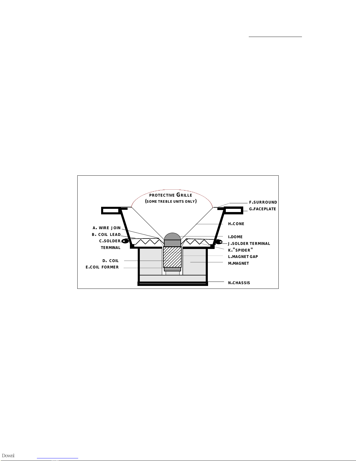
Allfaultscannormallybeconfirmedbyopeninguptheunitandexaminingthevoice
coil. Be warned that once a unit is opened it can not be reused and will have
to be replaced, so only do this if the unit is confirmed as being faulty.
DAMAGED UNITS
1. CURRENTOVERDRIVE:(Allunits)
Whenplayingthemusictoo loud (parties etc) or whendrivingalowpowered
amplifierintoclipping thecurrentacrossthevoicecoilcanbecome excessive
and cause the speaker voice coil to overheat.
First:
The enamel on the coil will start to blister and swell and this will cause
distortion as it will touch and rub the sides of the magnet gap as the voice
coilmovesforwardandbackward.
Next:
If the condition that is causing the blistering to occur continues, (the volume
isnotturneddown)theblisteringwillincreaseuntilitislargeenoughtorestrict
or stop the voice coil moving This will result in increased distortion, reduced
output and finally - no sound.
This can be seen by opening up the speaker and examining the voice
coil.
Remember, opening the unit is final and not reversible so the unit will
be need to be scrapped.
Finally:
The voice coil wire burns out and either goes open or short circuit. The unit
is now dead. This can be confirmed by checking with a multi-meter set on
ohms: Typical reading for a good unit is around 6- 8 Ohms.
2. HIGHFREQUENCYOSCILLATION:(Trebleunits)
Thiscanoccurwithunstableorfaultyamplifierswhichgeneratehighfrequency
signals (which may sometimes only be audible to the neighbourhood cat)
which will cause the unit to overheat due to the excessive High Frequency
current. - see point 1. These H/F signals can also occur where there are
earthingproblems.Somenamedamplifiersgonuts shouldyoudisconnectthe
earth while the volume is up, especially phono earths.
3. TRANSIENTDAMAGE:(Treble units)
Thiscanhappenwhenalargetransientsignalisappliedtothespeakersuch
aslettingthestylusfallontherecordwiththevolumesetveryhigh,fastcuing
(fast fwd or fast rev)of a tape recorder with the volume set high etc.
Thiswillcausethevoicecoil to"leap"forward(orbackword)beyondthelimit
ofitsnormal travelwhichmaybreakthevoice coilleadwireatthestart ofthe
coil.
4. DCVOLTAGEACROSSTHESPEAKER.(BassandMid-rangeunits)
Shoulda poweramplifierbecomefaulty andproduceDCacross thespeaker
outputthevoicecoil(s)willoverheatandbecomedamagedordestroyed(See
1). However as the treble units in passive speakers are driven through a by-
passfiltertheywillnotbedamagedunlessthevoltageissufficienttoburnout
the crossover, after which all the units may be destroyed.
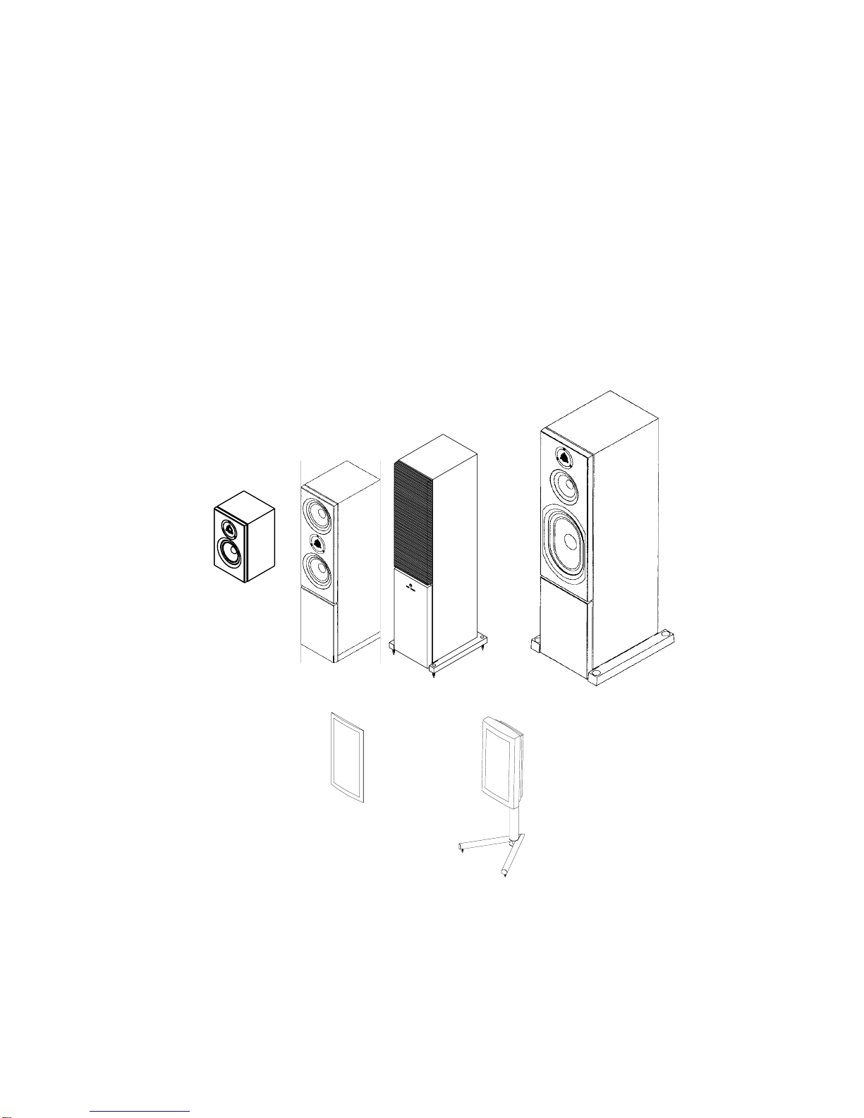
SPEAKER UNITS

Revised Dec 97
Copyright © 1991-1997 by Linn Products Limited. All Rights Reserved.
Page6 Index
SPEAKER UNITS
WARNING:
Caremustbe takentoensurethatthecauseofthedamageunitsisfoundand
corrected, so that the same thing will not happen again. This is not always
possible as customers seldom admit overdriving their speakers so the first
question could be: Was it a good party? If in any doubt, the system should
be checked, in particular the amplifiers and associated wiring should be
examinedandanyfaultsrectified. The amplifier should be testedunderload
for any nasties.
5. PLAYINGMUSICALINSTRUMENTS.(Allunits)
Electronic instruments and electric guitars can generate a lot of transients
withlittleornolimiting! Thiswillsimplyfrythetrebleunitsastheywerenever
designed to be used in this application.
ANY DAMAGE TO SPEAKER UNITS CAUSED AS PREVIOUSLY DETAILED IS
NOTDUEDUETOFAULTYMANUFACTURINGANDTHEREFORENOTCOVERED
BYMANUFACTURINGWARRANTY.
FAULTY UNITS.
TREBLEUNITS
Occasionallyonearlytrebleunitsweencounteredaproblemwiththesoftdome
where the internal join between the input wire and the voice coil wire had not
beensolderedcorrectly.Thisresultedinadryjointwhichcangiveaintermittent
or dead treble unit. Should you suspect this, gently tap the speaker unit while
playing some music. If the unit cuts out this may be the cause.
Again, this can be checked with a Multi-meter set on ohms: Typical reading is
around six Ohms. If the unit measures correctly gently move the dome with
your finger while measuring the speaker.
SPEAKERUNITCROSS-SECTIONDRAWING
12345678901
1
234567890
1
1
234567890
1
1
234567890
1
1
234567890
1
1
234567890
1
1
234567890
1
1
234567890
1
1
234567890
1
1
234567890
1
1
234567890
1
12345678901
1234567
1
23456
7
1
23456
7
1
23456
7
1
23456
7
1
23456
7
1
23456
7
1
23456
7
1234567
D. COIL
E.COIL FORMER
H.CONE
I.DOME
J.SOLDER TERMINAL
K."SPIDER"
L.MAGNET GAP
M.MAGNET
N.CHASSIS
PROTECTIVE GRILLE
(SOME TREBLE UNITS ONLY)F.SURROUND
G.FACEPLATE
A. WIRE JOIN
B. COIL LEAD
C.SOLDER
TERMINAL

Copyright © 1991-1997 by Linn Products Limited. All Rights Reserved. Page7
Revised Dec 97
Index
SPEAKER UNITS
FAULTY UNITS.
TREBLEUNITS(continued)
Finally this can be confirmed by opening the unit and checking for
damage.Ifthecoilshavenosignofover-drivingthenmeasurewiththe
meter.Itispossibletoscrapeoffsome of the enamel of the coil wirein
themiddleofthecoilandmeasuretoeachof the solder terminals, this
will tell you which side the fault is on. Then by examining the joint with
a magnifying glass (or microscope) you may be able to see the poor
joint. This can occur because the enamel was not removed properly
beforethejointwas soldered.
MID-RANGE AND BASS UNITS.
VOICECOILOFF-CENTRE.
The speaker has been wrongly assembled and the voice coil is off
centre, so that it rubs the magnet and causes distortion. The easiest
waytocheckforthisistouseasignalgeneratorandsweepthroughthe
frequencies slowly until you hear the distortion.
Itissometimespossibletofeelthisbyhand,bygentlypushingthecone
inwithyourhand,butyoumustdothisevenlyinastraightpistonmotion
inline with the cone movement or youwill distortthe cone and make it
rub.
SURROUNDUN-GLUED
It is possible to try carefully to glue this using CYANO-ACRYLIC,
(known as "superglue") or contact adhesive but these repairs are not
always successful as the repair must be air tight.
If you are in any doubt about a faulty speaker unit and do not wish to
opentheunityourself,theycanbereturnedtoLinnServiceforchecking.
Followthenormalreturnsprocedureasdescibedinthereturnsproce-
dure. It is important to ensure that speakers are properly packed for
return,usingoriginalboxes.ContactLinnSevricebeforereturningand
remember that we may need the pair back.

Revised Dec 97
Copyright © 1991-1997 by Linn Products Limited. All Rights Reserved.
Page8 Index
FAULTFINDING
LOUDSPEAKERS FAULT FINDING
Loudspeakersaregenerallyveryreliablewithveryfewproblems. Mostproblemsare
causedbyoverdrivingeg.playingofkeyboardsthroughspeakers,faultyamplifiers (DC
at output) and physical damage to units.
Symptom Fault Solution
Onespeaker Amplifierhas Switch off and allow to re-set.
dead tripped Check for likely cause and remedy.
Ensureenoughventilationforampli
fier.
Blown Bass Amplifierfaulty, Do not try with other speaker!
Driveunit. DConoutput. DC at speaker will cause the bass
unitto overheat andcan destroy the
voicecoil.
MeasureamplifieroutputforDCoff-
set.Repairamplifierasrequiredand
re-checkbeforeconnectingtospeak
ers.Trebleunitnotaffecteddueto
bypasscapacitor(Passivespeakers).
Overdrivenbass Replaceunit-chargeable.Advise
Customeronuse of speakers.
(Partiesordeafteenagers)
Trebleunitdead Blown treble Replace unit. Check other Unit.
speakerunit.
Deadorlow Trebleunitdome Replace unit. Chastisechild!
output-treble pushedin.
unit Trebleunitover- Replaceunit.
driven
Intermittentunit: Shortonspeaker Checkandrepair.
cables Break inside the unit on or around the
voicecoil.Seepreviouspageson
speakerunits.
Cuts out or Intermittent Checksoldering on unitterminals.
distorts at certain connectionon Check leadoutwiresvoicecoilforshort
toFrequencies Unit unit chassis. (bass and mid-range
only) repositionwireifrequired.
Faulty unit Checkwith multimeter- shouldread
between6 - 8 Ohms. Gently move
domeNOTCERAMICTREBLEUNITS!
(in and release) to check for dry or poor
joint at coil. Replace if faulty.
Dry joint on Removefromcabinetand
crossoverboard re-solder joints. Check legs of com-
ponents for breaks. For DMS with 4
Ohmcrossovertryanothercrossover
(swapfromotherspeaker).

Copyright © 1991-1997 by Linn Products Limited. All Rights Reserved. Page9
Revised Dec 97
Index
Symptom Fault Solution
Notrebleon Bi-wirelinks Replace links, or better still, fit bi-wire
bothspeakers missing cables.
Notrebleor Tri-wirelinks Replace links, or better still,fit tri-wire
bass on both missing cables.
speakers
Poor,orvery Suspectphasing:
little, bass. 1.Speakerswired Checkallspeakercablesbetween
outof phase amplifierandspeakers
2. Bass unit wired Check with battery and correct as
outof phase required.SeePhasing.
Poorsound Domespushedin Replace unit - see Section on
changingunits
Units loose Tighten unit screws using correct tool. Do
notover-tighten on plastic treble units as
you may crack the mounting plate.
Cabinetairleak Gentlypushcone(notTREBLEdome!)in
(non-portedspkrs) bass/midunit. Holdfor a secondortwo and
then release. If unit does not "pop" straight
out, but comes out gradually then the
cabinets have an air leak. See Sealing
Speakersectionforrepairprocedure.
Surroundunglued Replaceunit.
from unit chassis
Speakerunsteady Adjust spikes until speaker is rock steady.
onstand Make sure spikes and lock nuts are tight.
Useproperspanner,notjustfingers!
Iftheflooristoouneven,reposition speaker
ondifferentpart offloor,orrepairthe floor.
Somestands bases now have theoption
of 3 spikes which makes this easier.
Check speaker is not rocking on stand.
Adjust top spikes, or if they are fixed type,
(as on top of some stands) push speakers
onto spikes to bed them into speaker base.
Standinsert Screw Replaceinsert. Seepage30forproce-
problemsin miss-threaded dure.
Keildhspeaker and stuck.
Insertpushed Fitnew insert. See page 30forprocedure.
intothe speaker
FAULTFINDING

Revised Dec 97
Copyright © 1991-1997 by Linn Products Limited. All Rights Reserved.
Page10 Index
TO CHANGE SPEAKER UNITS
ToolsRequired
No.2pozidrivescrewdriver
2.5 mm allen key
Heavyduty(50W-100W)solderingironwithheavydutysolderingbit
Solder(Linntypeifpossible)
Heavy duty side cutters
General:
Before you start, clean work area/bench of anything that might
damage the cabinet. Remember, wood is easily marked so protect
cabinet from bench, tools, loose screws etc.
Silicone Sealed Units:
Oneaspectofthissealer,asusedwithearlierspeakers,isitsgluelike
properties. This can make it very difficult to remove units which have
beensealed with silicone.
Donottrytoleveranyunitoutwithascrewdriverundertheedgeofthe
frontplateasyouwillmarkthecabinet. Readthefollowinginstructions
beforeattemptinganyremoval/replacement.
KanLoudspeakers:
PleasenotethattheKanloudspeakerGrilleisgluedinpositionandwill
requiretoberemovedbeforereplacinganyunits. ToremoveGrille,cut
a hole in the cloth near the edge of the Grille, you will have to replace
with a new Grille. Insert a flat bladed screwdriver between the Grille
frameandthefrontbaffleandleveroff.Donottrytoleveroffagainstthe
cabinet as you may damage the cabinet.
TIP:TheotherwaytoremovetheGrillewithoutdamagingit andpossibly
re-using it is to pull it off with your fingers.
Slightlystretchthefabricwithyourfingersbypushinginslightlyoverthe
bassunit,thencatchthebottomoftheGrilleframewithyourfingersand
pull off. This does not always work but be warned: this can hurt!
Gasket Sealed Units:
TheLSrangeofLinnloudspeakers,IndexII,HelixII,NexusandKaber
were fitted with rubber gaskets, current models use foam gaskets.
These facilitate the removal and replacement of units and should not
present any problems.Use new gaskets if originals are torn etc.
GUIDELINESFORUPGRADEANDREPAIR

Copyright © 1991-1997 by Linn Products Limited. All Rights Reserved. Page11
Revised Dec 97
Index
CHANGING SILICONE SEALED TREBLE UNITS.
1. Removefixing screws andplace in asafe place.
2. Screwalargemachinescrewintooneexistingmountinghole.
M5 arm collar mounting screw is ideal.
3. Place claw hammer 'V' end onto bolt head with a thick
pieceofcardboard/woodunderthehammertoprotect
thebaffleand gently lever it out.
4. If it does not come out straight away, do
not force it.
Repeat this procedure on the remaining mounting holes in
turn,workingaroundtheunitandreleasingeachsideuntilthe
unit is free.
5. Make a note where the red
wiregoes (toterminalmarkedredor+).
6. Ensurethereissufficientsparewire.
Cutwiresclose to the unit, andremove.
Ifwireistooshorttoallowforthis,de-solderwiresfromtheunit. Always
protectcabinetfrom solder splashes.
8. Removeoldsealantfromthemountinghole,carefullyscrapeawaywith
aflatbladedscrewdriver.
9. For enclosed type treble unit, do not tin wire, but
removenotmorethen10mminsulationfromwires
-and twist to ensure there are no loose strands.
Observing polarity insert wires into terminal holes and
solder;useapproximately 20mm,28swg,solderperwire-
do not overfeed as solder ball will form inside the
unit.
Please note :
Please ensure that you follow these instruc-
tions. Using wire that is too long will cause
shortstomagnetorwires insidetheunit.Using
too much solder will cause solder balls to form
inside the unit which may result in rattles.
Forotherunits, cut andtin(or re-tin if de-soldered)
and solder wires to unit. Observe polarity; red wire to red mark or
terminalmarked(+). Inthecaseofveryearlyspeakersthecoloursmay
differ. Consult your notes (point 4) and wire as you found it.
10. Where treble unit is enclosed type, seal wire
holes with hot melt glue. Silicone sealer may
be used instead, the object is to make the
trebleunitairtight.
GUIDELINESFORUPGRADEANDREPAIR
Estimated Time
required: 20 minutes
Protection
Protection
10 MM
SOLDER
WIRE
TOO
LONG
GLUE

Revised Dec 97
Copyright © 1991-1997 by Linn Products Limited. All Rights Reserved.
Page12 Index
9. Rotate the treble unit loosely to twist the wires.
10. Placea bead ofsilicone around the top-plateinside edge. There
shouldbeenoughtoensure air-tight seal.
11. Place unit into cabinet and fit mounting screws.
WARNING: Be careful not to push T-nut into cabinet. Thread all screws in
carefully until slack is taken up, then tighten screws. Do not
overtightenasthiscandamage the front plate.
12. Clean off silicone sealer. When wet, scrape off excess with a flat
bladed screwdriver and clean with a soft cloth. When dry, trim with a knife
or simply rub it off with your fingers.
13. Re-fitGrilles:
Kan only - glue new Grille in position using silicone or hot melt glue.
14. Auditionspeaker.
15. Polish and clean for customer.
SILICONE
CHANGING SILICONE SEALED TREBLE UNITS.
GUIDELINESFORUPGRADEANDREPAIR

Copyright © 1991-1997 by Linn Products Limited. All Rights Reserved. Page13
Revised Dec 97
Index
GUIDELINESFORUPGRADEANDREPAIR
CHANGING MIDRANGE / BASS UNITS.
Tools Required
No.2pozidrivescrewdriver Sharpknife
4 mm allen keys M5nutrunner
5 mm allen keys Heavy duty side cutters
Heavy duty (50 - 100 Watt) soldering iron with heavy duty soldering bit
Solder(Linntypeifpossible)
Wideblade 3" -4" (70-100mm) paint stripper
Inadditionfor ISOBARIK BassUnit: M8tapandhandle
M8machinescrew 4BAnutrunner(forolderDMS)
General:
Beforeyoustart,cleanworkarea/benchofanythingthatmightdamagethecabinet.
Remember,woodiseasilymarkedsoprotectcabinetfrombench,tools,loosescrews
etc.
Twomethods ofsealingareused:
1. Silicone Sealed Units:
One aspect of this sealer, as used with earlier speakers, is its glue like properties.
Thiscanmakeitverydifficulttoremoveunitswhichhavebeensealedwithsilicone.
Donottrytoleveranyunitoutwithascrewdriverundertheedgeofthefrontplateas
you will mark the cabinet. Read the following instructions before attempting any
removal/replacement.
2. Gasket Sealed Units:
TheLS rangeofLinnloudspeakers arefittedwithfoam gaskets. (Someearlyones
usedrubber) Thesefacilitate the removal and replacement of units and should not
presentanyproblems.
To Change Silicone Sealed Mid-range and Bass Units in Sara and Kan
and Isobarik Midrange units. (For Isobarik bass unit see the next page)
1. Removefixing screws andplace in asafe place.
2. Inserta thinscrewdriverbetweenmountingholeandspeaker unitchassis
andlever off againstbaffle. You will require to workyour way aroundall the
mounting holes of the unit until you break the bond on the silicone sealer.
3. Lift unit out of cabinet.
4. Make a note where the red wire goes (terminal marked + or red dot).
5. Ensure there is sufficient spare wire, then cut wires close to the unit and
remove. If wire is too short to allow for this de-solder wires from the unit.
Remembertoprotectcabinetfromsoldersplashes.
6. Removeoldsealantfromthemountinghole.
7. Cutbackinsulationbyapprox.10mmandtinthewires(orre-tinifde-soldered).
Solderwirestounit. Observepolarity,redwiretoredmarkorterminalmarked
(+). In the case of very early speakers the colours may differ.
Therefore,consult your note (point4) and wire asyou found it.
Estimated Time
required: 20 minutes

Revised Dec 97
Copyright © 1991-1997 by Linn Products Limited. All Rights Reserved.
Page14 Index
GUIDELINESFORUPGRADEANDREPAIR
CHANGING MIDRANGE / BASS UNITS. (Continued)
8 Place a thick bead of silicone around the inside edge of baffle. This should
beenough to ensure airtightseal.
9. Place unit into cabinet and fit mounting screws.
WARNING: Be careful not to push T-nut into cabinet. Thread all screws
in carefully until slack is taken up, then tighten screws.
Donot over-tighten as thiscan damage the frontplate.
12. Clean off silicone sealer. When wet, scrape off excess with a flat bladed
screwdriverandclean with acloth.
13. Audition speaker.
14. Polish and clean for customer.

Copyright © 1991-1997 by Linn Products Limited. All Rights Reserved. Page15
Revised Dec 97
Index
TO CHANGE ISOBARIK SILICONE SEALED
BASS UNIT
1. Peel off hot melt covering the mounting bolts. Remove bolts
and place in a safe place.
2. Using an M8 tap, tap a thread into the top left mounting hole.
3. Screw in M8 machine screw.
4. Placeclawhammer'V'endontoboltheadwithathickpiece
of cardboard/wood protection under the hammer and
gently lever it out.
Ifitdoesnotcomeoutstraightaway,do not force.Repeat
above procedure on top right mounting hole, releasing
each side a little at a time until the unit is free.
5. Make a note (write it down!) where the red wire goes
(terminal marked+) or marked with red dot.
6. Ensure there is sufficient spare wire to cut
wirescloseto theunit,andremove.Ifwire is
too short to allow for this, de-solder wires from the unit. Always protect
cabinet from solder splashes.
7. Removeoldsealantfromthemounting hole. Carefully scrape away with
a flat bladed screwdriver.
8. Cut and tin (or re-tin if de-soldered) and solder wires to unit. Observe
polarity, red wire to red mark or terminal marked (+). In the case of very
earlyspeakersthecoloursmaydiffer.Therefore,consultyournote(point
5) and wire as you found it.
9. Loosely twist the wires to the unit.
10. Place a thick bead of silicone around the inside edge of baffle. This
should be enough to ensure airtight seal.
11. Place unit into cabinet and fit mounting screws.
WARNING: Be careful not to push T-nut into cabinet. Thread all screws
in carefully until slack is taken up, then tighten screws.
Do not over-tighten as this can damage the front plate.
12. Cleanoff silicone sealer. Whenwet, scrape off excess witha flat bladed
screwdriver and clean with a cloth.
13. Place speaker on its back an seal the bolt heads of the unit screws with
a drop of hot melt glue.
14. Audition speaker.
15. Polish and clean for customer.
Protection
GUIDELINESFORUPGRADEANDREPAIR Estimated Time
required: 20 minutes

Revised Dec 97
Copyright © 1991-1997 by Linn Products Limited. All Rights Reserved.
Page16 Index
CHANGING GASKET SEALED UNITS.
1. Remove unit fixing screws and place in a safe place.
2. Lift speaker unit out.
3. Make a note where the red wire goes (terminal marked + or red dot).
4. Make sure there is sufficient spare wire, then cut wires close to the unit and
remove. If wire is too short to allow for this, de-solder wires from the unit.
Protect cabinet from solder splashes.
5. Cutandsolderwirestounit. Observepolarity,redwiretoredmarkorterminal
marked(+).
6. Forenclosedtypetrebleunit,donottinwire,butremovenot
more then 10 mm insulation from wires -and twist to
ensuretherearenoloosestrands. Observingpolarityinsert
wires into terminal holes and solder; use approximately
20mm,28swg,solderperwire-donotoverfeedassolder
ball will form inside the unit.
Please ensure that you follow these instructions. Using
wire that is too long will cause shorts to magnet or wires
inside the unit. Using too much solder will cause solder
balls to form inside the unit.
Nowsealconnection withhot-meltglue. Siliconesealermaybeusedinstead.
The object being to make the treble unit air tight.
7. Loosely twist the wires to the unit. Simple way is to
spin the unit a few (2-4) times but do not drop it!
8. Check that the gasket is still usable, if in doubt use a new
gasket. Locate it in place, lining up the mounting holes.
9. Place unit into cabinet and fit mounting screws.
WARNING: Be carefulnottopushunitT-nutintocabinet.Threadallscrews
in carefully until slack is taken up, then tighten screws. Do not over-tighten
as this can damage the unit front plate.
13. Auditionspeaker.
14. Polish and clean for customer.
GUIDELINESFORUPGRADEANDREPAIR
Estimated Time
required: 20 minutes
10 MM
SOLDER
WIRE
TOO
LONG
GLUE

Copyright © 1991-1997 by Linn Products Limited. All Rights Reserved. Page17
Revised Dec 97
Index
How to remove the speaker baffle.
(LS7000 On wall ONLY)
PROCEDURE:
1. RemovetheSEKRITfromthewall.
2. Put the speaker carefully on it front on a clean, protected table/workbench.
3. Remove the 4 speaker input collars using the special tool provided with the
speaker.
4. Turn the speaker to other way up and remove the GRILLE and foam insert
using a small pointed object.
5. Remove the 8 retaining bolts from the front of the baffle, taking care not to
removetheunitscrews.
6. Put the speaker on its front and lift the cabinet from the baffle.
How to replace the bass unit
(LS7000 OnWall and LS6000 InWall)
Partsrequired.
Replacement bass unit. LS7000 On Wall SPKR020/1
LS6000In Wall SPKR 017/1
Procedure:
1. Ifspeakerisonwall(LS7000)removethefrontbaffle.
2. Pull off the speaker wire "push-on" connectors from the bass unit.
3. Turnthespeakertheotherwayupandundothe4M4screwsholdingthebass
unit to the front baffle.
4. IfClampingringisused,removethewholebassringandassembly-separate
the ring from the bass unit and fit to the new bass unit.
If clamping tabs are used, remove these, then the bass unit.
5. Remove old Gasket and fit a new one.
6. Fit the new bass unit ( see 3).
7. Refit the clamping tabs/ring with screws from the front baffle.
8. Reconnect the electrical "push-on" connections, red to the red terminal (+).
9. Refit the cabinet on wall (LS7000 only) using the 8 M4 screws.
10. Refit the socket collars and the front Grille.
11. Test
Estimated Time
required:
20minutes
CHANGINGCOMPONENTS INTHESEKRIT

Revised Dec 97
Copyright © 1991-1997 by Linn Products Limited. All Rights Reserved.
Page18 Index
How to replace the treble unit.
(LS7000 OnWall and LS6000 InWall)
Trebleunits LS7000 On Wall SPKR 019/1
LS6000In Wall SPKR 018/1
Procedure:
1. Removethespeakerbaffle.
(LS7000 On wall only- see section on previous page).
2. Pull off the speaker wire "push-on" connectors from the treble unit.
3. Turn the speaker the other way up and undo the three treble unit screws
holding the treble unit to the front baffle.
4. Removethetrebleunit.
5. Fit the new treble unit and gasket.
6. Ifaclampingring is used, fitM4screws,If self tappers
are used refit the old screws (This will depend on the
ageofthe speaker.)
7. Reconnecttheelectrical"push-on"con-
nections,redtotheterminalmarkedwith
a red dot (+).
8. Refitthecabinetusingthe8M4screws.
9. Refit the socket collars and the front
Grille.
How to replace the crossover.
(LS7000 OnWall and LS6000 InWall)
Partsrequired:
1 x crossover. LS7000 On Wall : PCAS 179/PT
LS6000InWall : PCAS 178/PT
Procedure:
1. Removethespeakerbaffle.
(LS7000 On wall only- see section on previous page).
2. Pull off the speaker wire "push-on" connectors from the drive units on the
crossover , note that these are identified on the crossover.
3. Unscrew the central fixing screw and washer.(In wall only)
4. Removethecrossover.
5. Fitthenewcrossoverusingthe"blackgunge"(fromtheoldcrossover)onthe
supportingpoststoprevent buzzing.
6. Replace the central screw. (In wall only)
7. Reconnectleads-redwiretoredterminalsandreconnectelectricalconnec-
tions.
8. Refit the cabinet to the baffle using the 8 M4 screws.
9. Refit the socket collars and the front Grille.
CHANGINGCOMPONENTS INTHESEKRIT

Copyright © 1991-1997 by Linn Products Limited. All Rights Reserved. Page19
Revised Dec 97
Index
TO SEAL A LOUDSPEAKER
Tools Required
No.2pozidrivescrewdriver 5 mm allen key
2.5 mm allen key for treble unit M5nutrunner
4 mm allen keys for bass unit 4BAnutrunner(forolderDMS)
Solder(Linntypeifpossible)
Heavyduty (50 -100 W) solderingiron with heavyduty soldering bit
Wideblade 3" -4" (70-100mm) paint stripper(for old Index)
PVAwoodglue Siliconesealerwithhanddispenser
Test Gear
Signal generator set at 10 - 20 Hz
Poweramplifier
Multi-meter (set to AC volts)
Sealed or Ported?
Linnproducetwotypesofspeakers,sealed(infinitebaffle)liketheKeltik,andported
enclosures like the Tukan
Infinite Baffle:
Thesearesealedenclosureswhichshouldbeasairtightaspossible. Anyairleaks
will result in a poor performance. The air seal also provides damping for the units
and slightly increases the power handling.
Itisthereforeimportantthatthecabinetisairtight. Overtheyearswehaveimproved
thesealinourloudspeakers,forexample,byusingbettermaterialsandcoatingthe
insidesofthecabinetwithspecialpaintswhichbothdeadenandsealthecabinets,
or by improving the laminations and laminating both sides of the cabinet walls.
Leaky Loudspeaker
It can be very difficult to find out where a speaker is leaking and you may prefer to
returnthespeakertoLinnforcheckingandrepair. However,therearesomethings
you can try first.
Procedure
Set up signal generator 10 - 20 Hz drive, and drive speaker with no more than 6 V
A/Cforshortburstsofnomorethan10to15seconds. UseMulti-metertosetvoltage
before connecting to speaker. Check for air leaks around the cabinet, baffle and
unitsbyfeelingaroundtheedgesandjointswiththebackofyourhand.Ifyoucannot
find any leaks, remember that your face is more sensitive to air movement.
Alternatively use a stethoscope to "listen" for leaks.
Instructions for Sealing:
1. Faulty Unit: Check unit surrounds are sealed to unit chassis.
Sometimes the rubber can become detached. The only proper solution is to
replace the unit. Re-gluing rubber to chassis is rarely successful.
2. CabinetLeaks: Eitherremovetheunitsandapplygluetoseamsofcabinetfrom
insidespeaker,orsealfromoutside. Remember to wipe off excessglue. Leave
todrybeforeauditioning.
SEALING SPEAKERS Estimated Time
required: 20 minutes

Revised Dec 97
Copyright © 1991-1997 by Linn Products Limited. All Rights Reserved.
Page20 Index
SIMPLESPEAKER PHASINGTEST
TO SEAL A LOUDSPEAKER (continued)
3. Leak around the Unit (silicone sealed): Remove unit. Clean off old sealant and
reapply silicone sealer. Ensure you use enough to seal the unit.
Leak around the Unit (gasket sealed): Remove unit, check gasket is not
damagedandisinplace.Cleanoffanyswarfordirtwhichmaybepresent. Ifin
doubt,fitanewgasket.Youshouldbeabletofitthisoverthelipoftheunitwithout
de-soldering the unit. Replace unit and tighten screws. Re-check for leaks .
SIMPLE SPEAKER PHASING TEST
Using a dcorDCsource(battery)ofapproximately1voltandconnecting the positive
terminalofthebatterytothepositivespeakerterminalandthenegativeterminal tothe
negativespeakerterminal,herearetheresultsyouwouldachieve:
Keltik Midrangemovesoutwards
Bassunitmovesoutwards
Kaber Mid / Bass unit moves outwards
Bassunitmovesoutwards
Keildh belowserialnumber15,400:
Both Bass units move inwards
aboveserialnumber15,400:
Both Bass units move outwards
Tukan Bassunitmovesoutwards
Sekrit Bassunitmovesoutwards
IndexII Bassunitmovesoutward
Index Plus Bassmovesinwards
Kan Bassmovesinwards
Helix Bassunitmovesoutwards
Nexus Bassunitmovesoutwards
Sara(old) Bassmoves inwards
Sara9 Bassmovesoutwards
DMS Bassmovesoutwards
Midrangemovesinwards
The treble units also move, but it is impossible to see. If phase is suspect, the
speakermustbedismantledandwiringchecked. Ifindoubt,contactthefactoryor
yourdistributor.
Other manuals for LOUDSPEAKERS
1
This manual suits for next models
11
Table of contents
Other Linn Speakers manuals