LINOVISION POE-SW806GM-Solar User manual

POE-SW806GM-Solar
User Manual
Updated on October 30, 2023
x1 x1 x1
POE-SW0604-Solar
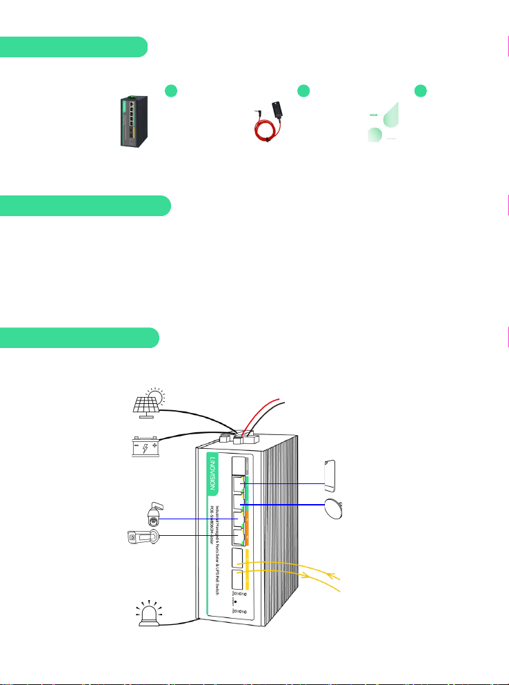
Package Contents
POE-SW806GM-Solar Temperature Sensor User Manual
Please read the user manual carefully before using. The improper operation may cause damage
to machine components.
Do not use in places near fire sources.
Do not throw it in the water and also wet the internal component in the machine.
Do not shorting the positive and negative poles of the battery interface with metal conductors.
1.
2.
3.
4.
5.
Important Notification
Connection Diagram
Please set DIP switches correctly before connecting any cables and device.
24V or 48V DC Input:
Supply DC Power to the Battery
Solar Panel
12V or
24V Battery
Passive 24V PoE
Devices
PoE Devices
PoE++ Devices
PoE+ Devices
To Fiber Switch or
Router
Alarm

Battery Type
Solar Panel
Type
Switch 1
Switch 2
Switch 3
Switch 4
Panel
12V Lead Acid
Battery
12V solar
panel
OFF
OFF
ON/OFF
( invalid)
OFF
24V Lead Acid
Battery
24V solar
panel
OFF
ON
ON/OFF
(invalid)
OFF
12V Lithium
Battery
12V solar
panel
ON
OFF
OFF
OFF
12V Lithium
Battery
24V solar
panel
ON
OFF
OFF
ON
14.8V LiFePO4
Lithium
Battery
12V/18V solar
panel
ON
OFF
ON
OFF
24V Lithium
Battery
24V solar
panel
ON
ON
OFF
OFF
29.6V LiFePO4
Lithium
Battery
24V/36V solar
panel
ON
ON
ON
OFF
Step 1: Configure DIP Switch
Make sure to set correct battery type, voltage, and solar panel type. Otherwise, the
system will not work properly or damaged.
Please follow these steps to setup this Solar PoE Switch.
1> Configure DIP Switch
2> Connect Battery
3> Connect Solar Panel
4> Connect external DC input for UPS power application– Skip this step if you do not use it
5> Connect PoE devices and wireless bridges
Hardware Installation
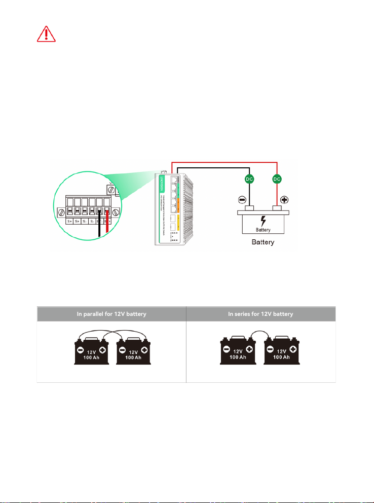
In parallel for 12V battery
In series for 12V battery
Warning:If the battery type is configured on web management page of the switch, the
battery type switch is invalid.
When you need to configure the battery type via the DIP button on the switch, please
ensure that the power of the device is turned off; turn on the power of the device after
the configuration is complete.
The above recommendations are for reference only. Select the solar panel based on the
actual open circuit voltage of the battery, the typical work voltage of the solar panel is
higher than the open circuit voltage of the battery.
If you accidentally configure the wrong power parameters in the GUI and cause the
device to power off, press the fourth button of the DIP button, dial up and down 5
times, and all the lights will flash once to restore.
Step 2: Connect Battery
Make connections according to the figure above, and choose the correct battery type according
to the figure below.
12V 100Ah + 12V 100Ah=12V 200Ah 12V 100Ah + 12V 100Ah=24V 100Ah

Step 3: Connect Solar Panel
Connecting Solar panels You can choose to connect one or two solar panels
(Either a positive or negative electrode can be connected to the solar panel):
The solar panel can power up the POE-SW806GM-Solar, at the same time, charge the
battery.
- To connect one solar panel.
- To connect two solar panels.

24V or 48V DC Input
Step 4: Connect external DC input for UPS power application– Skip this step if you do
not use it
Step 5: Connect PoE devices, IP cameras or wireless bridges
The V3 port serves as a DC charging port for solar cells, which is optional. When using
DC 24V, it charges 12V batteries, while DC 48V charges 24V batteries. If you want to
charge 12V batteries with DC 48V, you must first set it to wide voltage mode through
DIP settings or Web settings.
Ports 1~2 of the POE switch are for connecting 802.3af/at PoE devices, ports 3~4 are for
802.3bt or 24V passive PoE devices, and ports 5~6 are for the fiber switch or fiber media
converter.
24V CPE PoE++ Devices
Core Fiber Switch

Web Management
The following shows how to start up the Web Management of the POE-SW806GM-Solar. Please
make sure the manager PC must be set to the same IP subnet address.
For example, the default IP address of the POE-SW806GM-Solar is VLAN1 is 192.168.0.1. Then
the manager PC should be set to 192.168.0.x (where x is a number between 1 and254, except 1),
and the default subnet mask is 255.255.255.0.
Logging in to the POE-SW806GM-Solar
RJ45/UTP Cable
IP Address: 192.168.0.x IP Address: 192.168.0.1
Step 1: Use Web browser to enter IP address http://192.168.0.1 (default IP address)
Step 2: When the following dialog box appears, please enter the default user name “admin” and
password “admin” (or the password you have changed before).
Step 3: After entering the password the main screen appears. The above page shows the
information of solar power usage, PoE usage and battery capacity.
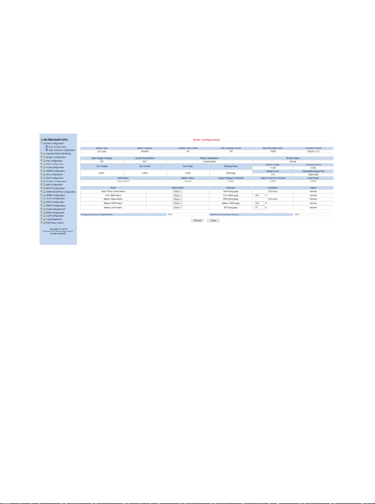
Step 4: The battery type and battery capacity will be auto display. The default of Wide
Capacity CHG -- Off.
E.g. If you want to connect a 24V 200W solar panel, and 24V 100AH lead-acid battery.
Battery configuration -- Auto, the battery type is automatically displayed 24V lead-acid battery.
If it is incorrect, please choose the battery type manually in the drop down box.
Battery Capacity: It is automatically displayed, if the data is incorrect you can enter the right data
manually (Formula: Wh= V*Ah).
Charging Current: The max charge current of POE-SW806GM-Solar is 10A max.
Wide voltage CHG: The default is Off for 12V solar panel connection. You connect 24V solar
panel, please adjust Wide voltage CHG -- ON.
LED Indicators
Status
Description
PoE(Port 1-2)
Green
On
48V 802.3af/at PoE device is connected
Orange
On
24V passive PoE device is connected
Off
Off
No power
PoE(Port 3-4)
Orange
On
PoE device is connected
Off
No power
Link/Act
Green
On
Port link is established
Blink
Data on TX/RX
Off
Port link down
PWR
Green
On
The device's power supply is operating normally, but the
system has not yet been activated.
Blink
The device's power supply is operating normally, and the
system initiates without any issues.
Off
The device is power off or failed
V1\V2
Green
On
The V1/V2 power is normal
Off
The V1/V2 power is off or failed
X1\X2
Green
On
The corresponding optical fiber port is connected
Off
The corresponding optical fiber port is not connected
Ring
Green
On
Ring setting is established
Off
Ring setting is off or failed
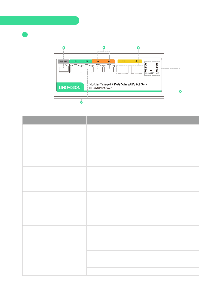
1Front Panel
2 * Gigabit SFP PortConsole Port
LED Indicators
2 * 90W Gigabit PoE Port
2 * 24V Passive/30W Gigabit PoE Port
Hardware Introduction

LED Indicators
Status
Description
BT:Battery
On
Battery is connected
Off
Battery is disconnected
VOT:PoE Voltage normal
On
PoE Voltage normal
Off
PoE Voltage abnormal
BOUT: Battery discharge
Solid on
Battery is discharging and battery capacity is 15%
Off
End of battery discharge or no discharge
Blink
1/2S: Battery capacity is ≤15%
SUN: Solar energy input
Solid on
Solar energy input is normal
Off
No solar energy input
Blink
1/2S: Solar energy is in delayed charging, the time is 10mins.
1/4S: Solar power voltage is wrong, stop charging
BIN: Battery charging
Solid on
Battery is charging and battery capacity is <98%
Off
Battery is charged fully or no charging
Blink
The battery is charging, and battery capacity is ≥98%
Battery percentage
Solid on
Reference the battery capacity 25% 50% 75% 100%
Alarm Input
Terminal
Grounding
Alarm Output
Terminal
Reset
Temperature
Sensor Input V1 V2: DC Input
DIP Switch Battery and Solar LED
Indicators
2Down Panel
V1 V2:DC Input1.
2. LED Indicators description
The solar POE switch can also be used as an ordinary switch, when the power input such as the
battery solar panel is not connected. V1, V2 any interface DC input 12-37V, the current maximum
10A, the device is a Ethernet switch; V1, V2 any interface DC input 37-57V, the current maximum
10A, the device is a POE switch. If both V1 and V2 ports supply power at the same time, select
the port with the highest voltage.

Solar & UPS Management
Flexible Power Supply and Priority
Solar Power > External DC > Battery
Built-in Solar Charge Controller
Yes (MPPT Controller)
Solar PV Input
300W Max
≤32V(in DC 12V Mode ) or ≤45V(in DC 24V Mode)
Max. Charging Current
15A
Support external DC charging
Yes
DC Input Range
For 12V Battery: DC 20-30V;
For 24V Battery: DC 30-57V
Built-in Battery Management
Yes
Battery Type
Lead Acid/Lithium/LiFePO4
Battery Input
12/24V 10A
Battery Capacity
200AH
Discharge Current
15A
POE Switch
Interfaces
(4) 10/100/1000Base-T RJ45 Ports
(2) 1.25G SFP Slot
(1) Console Port
PoE Outputs
Port 1-2: 802.3af/at PoE 30W (Pin 1/2+, 3/6-) or
Passive 24V PoE 24W (Pin 4/5+, 7/8-)
Port 3-4: 802.3bt PoE++ 60W (Pin 1/2/4/5+, 3/6/7/8-)
Total PoE Budge
120W
3Up Panel
Solar Power
Terminal: 12V/24V
Battery Power
Terminal: 12V/24V
V3: DC input
24V/48V : Supply DC
Power to the Battery
V3
Temperature
Sensor Input
Technical Specification

POE Switch
Exchange Capacity
12Gbps
Packet Forwarding Rate
8.94Mpps
Mac Address Table
8k
Packet Buffer Memory
4.1Mb
Jumbo Frame
10240 Bytes
System
Enclosure
Metal, fanless design
Dimension
6.14 x 4.53 x 2.6 Inches (156×115×66 mm)
Net Weight
2.82 lbs (1.28kg)
Power Consumption
5W Max (without PoE output) or 125W with PoE
outputs
Protection Level
6kV Lightning protection
6kV ESD Contact discharge
Working Temperature
-40 ℉ ~ 158 ℉ (-40℃~70℃)
Storage Temperature
-40 ℉ ~ 158 ℉ (-40℃~70℃)
Working Humidity
10%~90% RH non-condensing
Storage Humidity
5%~90% RH non-condensing

Switch Management
VLAN
Max 4K VLANs (802.1q Tagged VLAN, MAC-based
VLAN, IP-based VLAN, Protocol-based VLAN)
Port Configuration
LACP, Jumbo Frame, Port Shutdown, Link Aggregation(
Up to 8 aggregation groups and up to 8 ports per
group),
Port mirroring( One-to-One Many-to-One Tx/Rx/Both)
Security
IP-MAC-Port Binding, Support static and dynamic ARP,
DHCP Snooping, IEEE802.1x AAA, RADIUS/TACACS+,
RADIUS, Port Isolation
Access Control
Port based authentication, Secure Command Line
Interface (CLI) management with SSHv1/SSHv2,
Broadcast/Multicast/Unicast Storm Control, Port MAC
address filtering,
QoS
Port-based (uplink and downlink traffic of a single port
can be restricted), 802.1p-based Classification, Support
WRR, SP, WFQ, DSCP-Based Classification, ACL-Based
Classification
Management
Web-based GUI, Command Line Interface (CLI) through
console port, telnet, SSH, SNMPv1/v2c/v3
Solar & Battery Controller
Solar Controller
PV input voltage, PV input current, PV status, DC
output voltage, DC output current,
Battery Controller
Battery type, Battery status, Battery voltage, Battery
capacity, charging current, charging voltage, discharge
voltage, discharge current.
External DC Chargin
AC-DC voltage, AC-DC current, AC-DC status
Alarm Events
AC-DC status, solar timing check, SYS temp sensor,
Battery temp sensor, Battery status, battery capacity,
alarm input
POE Port Management
PoE Type
Active 48V, Passive 24V, BT 60W
PoE Port Control
ON/Off Control, PoE Budget
Software Functions
Table of contents
Other LINOVISION Switch manuals


