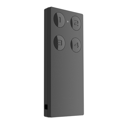
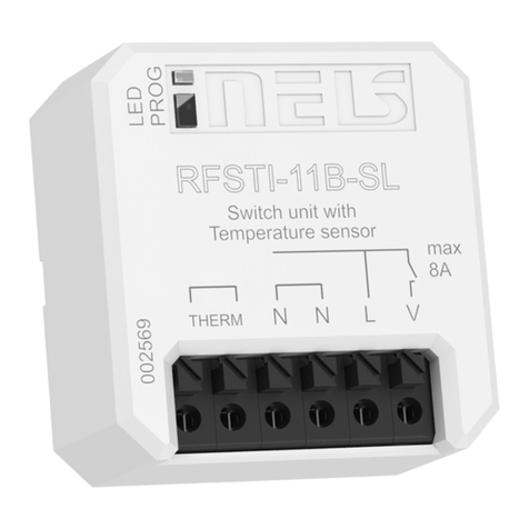
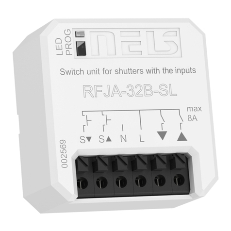
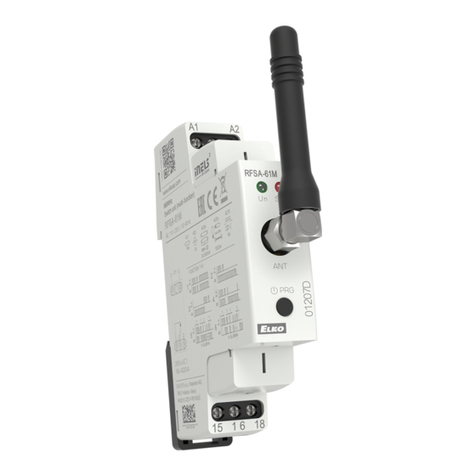
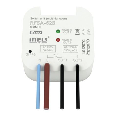
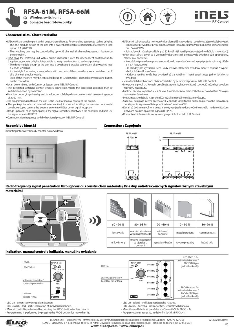
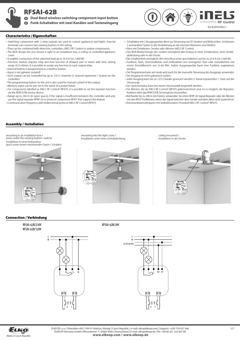
iNels RFJA-12B User manual

02-46/2015 Rev.1
RFJA-12B/230V, RFJA-12B/24VDC
Switch unit for shutters
EN
L N
L
N
PE
M
+
-
- +
M
12-24V DC
RFJA-12B/230V RFJA-12B/12VDC
1/4
☺
☺
☺
☺
☺
RFRP-20
Characteristics /
• The switching unit for blinds has 2 output channels used to control garage doors, gates, blinds,
awnings, etc.
• It can be combined with Control or System units iNELS RF Control.
• The BOX design lets you mount it right in an installation box, a ceiling or motor drive cover.
• RFJA-12B/230V: connection of switched load 2 x 8A (2 x 2000 W).
• RFJA-12B/24VDC: contactless quiet switching.
• Short presses of the controller enable tilting of lamellas, and a long press enables you to draw the
blinds up or down to the end position.
• Each of the units may be controlled by up to 32 channels (1 channel represents 1 button on the
controller).
• The programming button on the unit is also used for manual control of the output.
• Range up to 100 m (in open space), if the signal is insufficient between the controller and unit, use
the signal repeater RFRP-20.
• Communication frequency with bidirectional protocol iNELS RF Control.
Assembly /
mounting into a non-conducting drive housing flush mounting ceiling mounted
Connection /
Radio frequency signal penetration through various construction materials /
60 - 90 % 80 - 95 % 20 - 60 % 0 - 10 % 80- 90 %
brick walls wooden structures
with plaster boards
reinforced
concrete metal partitions common glass
Unidad de conmutación para persianas
ES
ELKO EP, s.r.o. | Palackého 493 | 769 01 Holešov, Všetuly | Czech Republic | e-mail: [email protected] | Support: +420 778 427 366
ELKO EP ESPAÑA, S.L. | C/ Josep Martinez 15a, bj | 07007 Palma de Mallorca | e-mail: [email protected] | Tel.: +34 971 751 425 | Fax: +34 971 428 076
www.elkoep.com / www.elkoep.es
Característica
• Unidad para persianas tiene 2 canales de salida utilizado para controlar puertas de garaje, barreras,
persianas, toldos...
• Se puede combinar con Controlador o Unidades del sistema iNELS RF Control.
• Versión B „pastilla“ ofrece montaje directamente a la caja de instalación, techo o a la cubierta del
motor controlado.
• RFJA-12B/230V: permite conexión de cargas 2 x 8A (2 x 2000W).
• RFJA-12B/24VDC: conmutación silenciosa sin contacto.
• Pulsaciones cortas permiten la inclinación de lamas, la pulsación larga subir / bajar persianas a la
posición final.
• Cada unidad de conmutación se puede controlar con hasta 32 canales (1 canal presenta un botón
en el controlador).
• Botón de programación en la unidad también sirve como control manual de salida.
• Alcance de hasta 100 mts (al aire libre), en caso de señal insuficiente entre controlador y la unidad
se puede utilizar el repetidor RFRP-20.
• Frecuencia de comunicación con protocolo bidireccional iNELS RF Control.
Montaje
montaje en cubierta no conductiva del motor montaje en caja universal montaje al falso techo
Conexión
Transmisión de señales de radiofrecuencia en varios materiales de la
construcción
pared de ladrillo estructuras de
madera con placas
de yeso
hormigón armado chapas
metálicas vidrio normal

02-46/2015 Rev.1
RFJA-12B/230V, RFJA-12B/24VDC
Switch unit for shutters
EN
123
PROG > 1s
X x
1 x
PROG > 1s
1 x
4
PROG > 5s
1 x
5
=1s ... 4min. + 2s
7
PROG < 1s
1 x
6
=1s ... 4min.
+ 2s
<3 s
>3 s
xxxxxx
2/4
Indication, manual control /
button / LED • LED STATUS - indication of the device status.
• Manual control is performed by pressing the PROG button.
• Programming is performed by pressing the PROG button for more than 1s.
Functions and programming with RF transmitters /
Function description /
Shooting fins, short travel. Blinds starts / descend to the end position.
Programming /
Repeatedly press of
programming button on
actuator RFJA-12B for no
longer then 1 second will roll
up shutters into final upper
position.
Press of programming button
on actuator RFJA-12B for
1second will activate actuator
RFJA-12B into programming
mode. LED is flashing in 1s
interval.
Select and press one button
on wireless switch, to this
button will be assigned
Function 1. Second control
position “down”, will be
assigned automatically (on the
same half of wireless switch).
Press of programming button
longer then 5 seconds, will
activate actuator into timing
mode. LED flashs 2x in each 1s
interval.
Press of the button on wireless switch with assigned function for shutters down
will roll the shutters down. Release the press of this button 2 seconds after the
shutter is stopped by lower final switch.
Press of the button on wireless switch with assigned function for shutters up will
roll the shutters up. Release the press of this button 2 seconds after the shutter
is stopped by upper final switch. Duration of rolling up and down is than saved
into memory of reciever.
Press of programming button
on reciever RFJA-12B shoter
then 1 second will finish
programming mode (LED
switches off).
Programming with RF control units /
adress / The address listed on the front of the actuator is used for programming and
controlling actuators by RF control units.
Unidad de conmutación para persianas
ES
ELKO EP, s.r.o. | Palackého 493 | 769 01 Holešov, Všetuly | Czech Republic | e-mail: [email protected] | Support: +420 778 427 366
ELKO EP ESPAÑA, S.L. | C/ Josep Martinez 15a, bj | 07007 Palma de Mallorca | e-mail: [email protected] | Tel.: +34 971 751 425 | Fax: +34 971 428 076
www.elkoep.com / www.elkoep.es
Indicación, control manual
botón PROG LED STATUS - indicación del estado de la unidad.
• Control manual se realiza mediante el botón PROG.
• Programación se realiza mediante el botón PROG < 1s.
Funciones y programación con RF controlador
Descripción de función
Giro de lamelas o movimientos cortos hacia arriba / abajo. Persianas suben / bajan hasta la posición final.
Programación
Pulse repetidamente la tecla
de programación durante
menos de 1 segundo en la
unidad RFJA-12B la persiana
sube a la posición final.
Pulsando el botón de
programación de la unidad
RFJA-12B durante más de
1 segundo, entra al modo
de la programación. LED
parpadea en intervalo de 1
segundo.
Pulsación albotónseleccionado
del RF controlador se asigna
la función "subir". Segunda
posición del control „bajar”
se asigna automáticamente
(en caso 4- botones en misma
mitad del controlador).
Al pulsar el botón de
programación durante más de
5 segundos, la unidad entra al
modo de temporizador. LED
parpadea 2x en intervalos de
1 segundo.
Seleccione y pulse el botón en el controlador RF destinado para mover
las persianas abajo. El pulso al botón liberar 2 segundos después de que la
persiana está detenida por el final de carrera inferior.
Seleccione y pulse el botón en el controlador RF destinado para mover
las persianas arriba. El pulso al botón liberar 2 segundos después de que la
persiana está detenida por el final de carrera superior. La unidad memorizará
este tiempo de movimiento.
Pulsando el botón de
programación de la unidad
RFJA-12B durante menos de 1
segundo, terminará el modo
de programación. LED se
apaga.
Programación con Unidades del sistema RF
dirección Para la programación y control mediante Unidades de sistema RF sirve la
dirección indicada en la parte frontal de la unidad.
02-46/2015 Rev.1
RFJA-12B/230V, RFJA-12B/24VDC
Switch unit for shutters
EN
3/4
PROG > 5s
1 x PROG > 8s
1 x
Delete actuator /
Deleting one position of the transmitter /
By pressing the programming button on the actuator for
5 seconds, deletion of one transmitter activates. The LED
flashes in an interval of 1s.
Pressing the required button on the transmitter deletes it from
the actuator's memory.
The LED goes out and the actuator returns to operating mode.
Deleting the entire memory /
By pressing the programming button on the actuator for
8 seconds, deletion occurs of the actuator's entire memory. The
LED flashes three times and goes out, then again flashes three
times and goes out.
The actuator goes into the programming mode, the LED flashes
in 0.5s intervals (max. 4min.).
You can return to the operating mode by pressing the Prog
button for less than 1s.
Technical parameters /
* Identical with supply voltage.
Supply voltage:
Apparent input:
Dissipated power:
Power without load:
Power under load:
Supply voltage tolerance:
Output
Number of contacts:
Rated current:
Permanent current:
Switching power:
Peak current:
Switching voltage:
Switching output voltage*:
Mechanical service life:
Electrical service life (AC1):
Control
RF, by command from transmitter:
Manual control:
Range in free space:
Other data
Operating temperature:
Operating position:
Mounting:
Protection:
Overvoltage category:
Contamination degree:
Terminals:
Length of terminals:
Dimensions:
Weight:
Related standards:
Attention:
The minimum distance between the controller (system unit) and the actuator must not be less
than one centimeter.
Between the individual commands must be an interval of at least 1s.
Unidad de conmutación para persianas
ES
ELKO EP, s.r.o. | Palackého 493 | 769 01 Holešov, Všetuly | Czech Republic | e-mail: [email protected] | Support: +420 778 427 366
ELKO EP ESPAÑA, S.L. | C/ Josep Martinez 15a, bj | 07007 Palma de Mallorca | e-mail: [email protected] | Tel.: +34 971 751 425 | Fax: +34 971 428 076
www.elkoep.com / www.elkoep.es
Borrar la unidad
Borrar una posición del controlador
Con un largo pulso al botón de programación de la unidad RF
por un período de 5 segundos se activará modo "borrar" un
solo transmisor. LED parpadea en intervalos de 1s. Al pulsar el
botón del controlador se elimina de memoria de la unidad. LED
se apaga y la unidad vuelve al modo operativo.
Borrar toda memoria
Con un largo pulso del botón de programación de la unidad
durante 8 segundos se borrará toda memoria de la unidad. LED
parpadea tres veces, luego se apaga de nuevo tres veces y se
apaga.
Unidad entra al modo de programación, el LED parpadea en
intervalos de 0.5 s (máx. 4 min.).
Para volver al modo operativo, pulse el botón Prog por menos
de 1 segundo.
Especificaciones técnicas
12-24 V DC
x
x
0.5 W
25 W
x
x
1 A
x
1.5 A
x
12-24 V DC*
x
x
* Consistente con la tensión de alimentación.
Tensión de alimentacion:
Consumo aparente:
Consumo de perdida:
Consumo sin carga:
Consumo con carga:
Tolerancia de alimentación:
Salida
Número de contactos:
Corriente nominal:
Corriente continua:
Potencia de conmutación:
Pico de corriente:
Tensión de conmutación:
Tensión.de conm. de salida*:
Vida mecánica:
Vida eléctrica (AC1):
Control
Orden RF desde controlador:
Control manual:
Rango al aire libre:
Más información
Temperatura de funcionamiento:
Posición de funcionamiento:
Montaje:
Protección:
Categoría de sobretensión:
Grado de contaminación:
Salidas:
Longitud de hilos:
Dimensiones:
Peso:
Normas conexas:
230 V AC / 50 - 60 Hz 120 V AC / 60 Hz
7 VA / cos φ = 0.1 7 VA / cos φ = 0.1
0.7 W 0.7 W
x
x
+10 -15 %
2 x switching / NA (AgSnO2)
8 A / AC1
x
2000 VA / AC1
10 A / <3 s
250 V AC1
x
1x107
1x10⁵
868 MHz, 915 MHz, 916 MHz
PROG (STOP, %, STOP, &)
up to / hasta 100 m
-15 ...+ 50 °C
any / cualquiera
free at lead-in wires / libre en los cables de conexión
IP30
III.
2
CY wire, cross section / hilos CY, sección 4 x 0.75 mm2
90 mm
49 x 49 x 21 mm 49 x 49 x 13 mm
46 g 22 g
EN 60669, EN 300220, EN 301489 R&TTE Directive, Order. No 426/2000 Coll. (Directive 1999/EC
) /
EN 60669, EN 300 220, EN 301 489 directiva RTTE, NVč.426/2000Sb (directiva 1999/ES)
Advertencia:
La distancia mínima entre el controlador (unidad de sistema) y la unidad no debe ser inferior a 1 cm.
Entre los diferentes ordenes debe pasar al menos 1s.

02-46/2015 Rev.1
RFJA-12B/230V, RFJA-12B/24VDC
Switch unit for shutters
EN
4/4
Warning
Instruction manual is designated for mounting and also for user of the device. It is always a part of its packing.
Installation and connection can be carried out only by a person with adequate professional qualification upon
understanding this instruction manual and functions of the device, and while observing all valid regulations.
Trouble-free function of the device also depends on transportation, storing and handling. In case you notice any
sign of damage, deformation, malfunction or missing part, do not install this device and return it to its seller. It
is necessary to treat this product and its parts as electronic waste after its lifetime is terminated. Before starting
installation, make sure that all wires, connected parts or terminals are de-energized. While mounting and servicing
observe safety regulations, norms, directives and professional, and export regulations for working with electrical
devices. Do not touch parts of the device that are energized – life threat. Due to transmissivity of RF signal, observe
correct location of RF components in a building where the installation is taking place. RF Control is designated only
for mounting in interiors. Devices are not designated for installation into exteriors and humid spaces. The must not
be installed into metal switchboards and into plastic switchboards with metal door – transmissivity of RF signal is
then impossible. RF Control is not recommended for pulleys etc. – radiofrequency signal can be shielded by an
obstruction, interfered, battery of the transceiver can get flat etc. and thus disable remote control.
Unidad de conmutación para persianas
ES
ELKO EP, s.r.o. | Palackého 493 | 769 01 Holešov, Všetuly | Czech Republic | e-mail: [email protected] | Support: +420 778 427 366
ELKO EP ESPAÑA, S.L. | C/ Josep Martinez 15a, bj | 07007 Palma de Mallorca | e-mail: [email protected] | Tel.: +34 971 751 425 | Fax: +34 971 428 076
www.elkoep.com / www.elkoep.es
Advertencia
El manual de uso está dirigido para la instalación y el usuario del dispositivo. Manual siempre está incluido en embalaje.
La instalación y conexión puede realizar sólo personal con adecuadas cualificaciones profesionales, de conformidad
con todas las regulaciones aplicadas, y que está perfectamente familiarizado con estas instrucciones y funciones del
dispositivo. Función del dispositivo también depende del transporte, almacenamiento y la manipulación. Si se observa
cualquier signo de daño, deformación, mal funcionamiento o pieza que falta, no instale este producto y devolvelo al
vendedor. Con el producto y sus componentes debe ser tratado después de su vida útil como con residuos electrónicos.
Antes de iniciar la instalación, asegúrese de que todos los cables, partes o terminales conectados están sin la conexión a
la red. En el montaje y el mantenimiento se deben observar las normas de seguridad, normas, directivas y reglamentos
para trabajar con equipos eléctricos. No toque las partes del dispositivo que están conectadas en la red - puede producir
peligro de vida. Debido a la transmisibilidad de la señal RF, observe la correcta ubicación de los componentes RF en
un edificio donde la instalación se lleva a cabo. RF Control está diseñado para montaje en interiores, las unidades no
están diseñados para la instalación en exteriores y espacios húmedos, no se pueden instalar en cuadros eléctricos de
metal y en cuadros eléctricos plásticos con puerta de metal - lo que empeora transmisividad de la señal RF. RF Control
no se recomienda para el control de dispositivos que ofrecen funciones vitales o para controlar dispositivos tales como
bombas, el. calentadores sin termostato, ascensores, montacargas, etc. - Señal de radiofrecuencia puede estar bloqueado
por una obstrucción, interferida, la batería del controlador puede estar ya sin energía, etc. y por lo tanto el control remoto
puede ser incapacitado.
Other iNels Switch manuals

iNels
iNels RFSAI-11B-SL User manual

iNels
iNels RFSA-11B User manual

iNels
iNels RFSA-61M/MI User manual

iNels
iNels RFSAI-61B User manual

iNels
iNels RFSAI-61B Series User manual

iNels
iNels RFSA-61B User manual

iNels
iNels RFSAI-11B-SL User manual

iNels
iNels RFSAI-62B User manual

iNels
iNels RFSAI-62B User manual

iNels
iNels RF KEY-40/W User manual

iNels
iNels RFSAI-11B-SL User manual

iNels
iNels RFSA-11B User manual

iNels
iNels RFUS-61 User manual

iNels
iNels RFSA-11B User manual

iNels
iNels RFSOU-1 User manual

iNels
iNels RFSA-61M User manual

iNels
iNels RFSA-11B User manual

iNels
iNels RFSAI-62B/230V User manual

iNels
iNels RFSAI-61B User manual

iNels
iNels RFSA-11B User manual