Lionel TrainMaster CAB-1 User manual

71 2867 250
Rev A
tf\QLionel
~ TrainMaster®
OWNER S MANUAL
The Lionel TrainMaster CAB-II PM-I handheld con-
troller complies with Part 15 of the FCC Rules.
Operation is subject to thefollowing two conditions: (1)
This de-vicemay not cause harmful interference, and (2)
this device must accept any interference received,
including interference that may cause undesired opera-
tion.
Changesor
modijcaiions
made to Lionel TrainMaster that
arenot expresslyapprovedby LionelTrainsInc.for compli-
ance could void your authority to operatethis equipment.
Note: The Lionel TrainMaster CAB-II PM-I handheld
controller has been tested and found to comply with the
limits for a Class
B
digital device and Class
C
trans-
mitter, pursuant to Part 15 of the FCC Rules. These
limits are designed to provide reasonable protection
against harmful interference in a residential installa-
tion. The Lionel TrainMaster handheld controller gen-
erates, uses, and can radiate radio frequency energy
and, if not installed and used in accordance with the
instructions, may cause harmful interference
to
radio
communications. However, there is no guarantee that
interference will not occur in a particular installation.
If your Lionel TrainMaster handheld controller does
cause harmful interference
to
radio or television recep-
tion (determined by turning the equipment off and on),
correct the interference by trying one or more of thefol-
lowing measures:
• reorientor relocatethe receivingantenna (PowerMaster)
• increasethe separation between equipment and receiver
• connect the equipment into an outlet on a circuit dif-
ferent from that to which the receiver is connected
• consult your authorized Lionel TrainMaster dealerfor
additional assistance. .
© 1994 Lionel Trains lnc.
50625 Richard W. Blvd.
Chesterfield, MI 48051-2493
Lionel, TrainMaster, PowerMaster are registered trade-
marks and PowerHouse, CAB-I, Railsounds II, and
Liontech are trademarks of LTI. Big Red is a registered
trademark of AbleNet lnc. and is used with permission.

Welcome
to
UoneI TrainMaster
o:-- -- 01 :,'ollr purchase
. Tr. -nZvfastersystem,
f': :1G11PLi
J•
or the future
and Liontech.
The
Uonel
TrainMaster system
The basic lio el Train' laster system
consists of ·our com: nents: Power-
Master, Pox .erl-Iouse, Biz Red con-
trol button, and
C-\B-l
controller.
CAB--l
iM -
troller
p(TtJJerMast~
base
~ Big Red®switch
2
Lionel TrainMaster
Installing PowerMaster
and PowerHouse
Connect PowerHouse with PowerMaster by
inserting the power supply's connecting cable,
into PowerMaster's input jack.
Start by connecting your layout's track
wires to PowerMaster's binding posts
labeled A and U. The A wire con-
nects to the center rail, the U to the outer
rail.Next, connect PowerHouse by insert-
ing its connector into PowerMaster's
input jack.Plug PowerHouse into a wall
outlet (120 volts, 60 cycles). Make sure
the switches on the side of Powerlvlas-
ter are set to
Run
and
Conventional.
Turn
on PowerHouse.
(Always
switch offPow-
erHouse any time you're not operating
your railroad.) ,
We recommend using PowerHouse to
electrifyTrainMaster. However, any AC-
output transformer with a
maximum out-
put of
21
volts and a circuit breaker of 7
amps or less
will work. Purchase a Pow-
erMaster power adapter cable (part no.
6-01-2893-000,available at your Lionel
dealer). Connect the cable wire outfit-
ted with .a fuse to the A (or hot ) ter-
minal on your transformer; connect the
other wire to the U (or common ) ter-
minal. Plug the power adapter cable into
PowerMaster, then plug the transformer
into a conventional wall outlet (120volts,
Lionel TrainMaster
3

60 cycles) and set its throttle on maxi-
mum.
Warning: ensure your transformer
does not exceed a 21-volt AC maximum out-
put.
On top of PowerMaster are two
lights. When PowerMaster is receiving
electricity, the green light illuminates.
The red light flashes when PowerMaster
is receiving signals from CAB-I.
Many model railroaders use 'block con-
trol to achieve multiple-train opera-
tion on their layouts. Block control
means track sections are electrically iso-
lated from each other, and receive power
ria a itch or an automated system
or
electrification like relays. Ifyour rail-
road has block control, install Power-
_Iaster
bet-•.reen
the source electricity and
the block control panel.
Install four AA alkaline batteries in CAB-l.
Make sure the
"+"
ends match the symbols
inscribed in the battery compartmentbase.
BOOST always awakens a sleeping
CAB-I.) Turn the throttle clockwise (to
the right) and the train's speed
increases. Turn it counterclockwise (left)
and speed decreases. The dial has no
off position.
Using CAB l
Today' modern railroads use handheld
remote controllers to switch locomotives
in yards. Yourlionel TrainMas-
ter CAB-l is based on this
real-lifetrend Press abut-
ton or turn the throt-
tle, and CAB-l
sends a radio sig-
nal to PowerMas-
ter. PowerMaster
then applies the appro-
priate amount of electricity to the track.
CAB-l's command buttons provide one-
touch controlovermany locomotivefunc-
tions: change direction, hit the brake,
boost your locomotive's speed, select
momentum or even switch to a differ-
ent track controlled by another Power-
Master.
Note:
many CAB-l buttons are
designed for use with future products.
They currently have no effect on oper-
ations.
Basic control
with one PowerMaster
To get CAB-l into action, install four
alkaline
AA batteries (not included).
Extend the telescoping antenna halfway
for small layouts, completely for larger
railroads. Press BOOST,turn the throt-
tle, and the handheld wakes up. (It
goes to sleep after 30 seconds of inac-
tivity to extend battery life. Pressing
Address your track by
pressing TRACK ( TR )
and
1/1
on the 10-digitkey-
pad. You only have to do
this
once.
This lets Power-
Master know you're ready.
Now every CAB-l action
button is ready to use.
TR
CJ
1
o
4
Lionel TrainMaster Lionel TrainMaster 5

Throttle
Controls your locomo-
tive's speed. Turn the
throttle clockwise (right)
to increase locomotive
speed, counterclockwise
(left) to slow it down.
Whistle/Horn
Activates the whistle or
horn sound effect in any
Lionel locomotive. Press
WHISTLE/HORN to
beginthesound;releasethe
button to end it.
Bell
Starts or stops the tolling
bell in any Lionel Rail-
Sounds or Railsounds II-
equipped locomotive.
Press BELLto begin the
sound, again to stop it.
Direction
Changes the locomotive's
direction. Press DIREC-
TIO~. Your locomotive
ill
sequence to the next
reverse-unit direction
(fon -ard, neutral, or
reverse).
Boost
Speeds up your locomo-
tive. BOOST provides
increased electricitywhile
you press the button.
Release it, and the power
returns to the previous
throttle level.
Brake
Slows your locomotive
6
BRAKE
~
wsnJHRN
[}[]
HALT
BELL
[ ]
AUX1
IT]
DIR
ill]
BOOST
~
o
o
down. BRAKEdecreases
the electricity supplied to
the locomotive.Yourloco-
motive will eventually
come to a stop ifyou con-
tinue to depress BRAKE.
Release BRAKE,and the
train will return to its pre-
vious speed setting.
Halt
Provides an immediate,
emergency stop to all
operations. Since Power-
Master will automatically
shut down,
use
HALT
only
in emergency situations.
To
begin operating again,
readdress the track(TR
+
1)
and turn the throttle.
Track power-down
TellsPowerMastertocease
electrification of the
addressed track
only.
If
you're about to place a
locomotiveontrack,you'll
want that track deacti-
vated. Press AUXI and
"0"
onthe 10-digitkeypad.
.This cuts power to the
addressed track. When
you're ready to begin
operations, turn the throt-
tle to reestablish power.
Note:
Press AUXI once
when using
" -
single Pow-
erMaster. If you need to
deactivate the same
track later, hit 0 on the
Hi-digit keypad.
Stall
A Lionel locomotive's
Lionel TrainMaster Lionel TrainMaster
7

direction is determined by
the reverse unit. This
device controls the flow of
electricity to a locomo-
tive's motor(s), producing
movement in either direc-
tion or no movement at all.
Many railroaders prefer to
run locomotives only in
forward. With Lionel
TrainMaster, you can do
so simply by setting a
stall voltage with CAB-
1. Stall voltage means
when you turn the throt-
tle to zero, the locomo-
tive will stop. However,
when you power up
again, the locomotive will
continue in the same
direction.
To set your locomotive's
stall voltage, remove the
small cover plate located at
thebottomofCAB-1.Power
up the locomotive. Press
the SET button located
inside. Track power will
go to zero. Power up your
locomotive; it'll only reach
half power once SET has
been pressed. Reduce the
locomotive's speed until
it just stops. Press SET
again. Power up the throt-
tle, and your locomotive
will commence stall-volt-
age operations. Note:
Because every reverse
unit is different, set the
stall voltage each time you
change locomotives.
Warning:use low momen-
tum when setting stall
voltages. Read on.
L
o
Momentum
Imagine the titanic weight
of a fully loaded freight
train.Now imagine theper-
formance ofthe locomotive
pulling that train. It starts
slowly, takes more time to
gain speed, and requires
more distance to stop.
Lionel TrainMaster cap-
tures that concept-momen-
turn-with the push of a
button on your CAB-I.
Remove the small cover
plate at thebottom ofCAB-
1.Inside you'll find LOW,
MEDIUM, and HIGH
momentum buttons. Press
and hold the desired set-
ting for two seconds. Re-
adjust momentum at any
time. Note: Always use
LOW momentum when
setting stall voltage. Use
LOW momentum during
your introductory experi-
ence with TrainMaster.
M
o
H
o
SET
o
Installing additional PowerMasters
One PowerMaster delivers 135watts
of electricity to a model rail~-
road. However, some ~.
~ o
model railroaders have '
huge layouts with big
power requirements. .'
.1 .
Others have sophis-
pUS
ticated track plans ~~
that allow simultaneous .,/
o
multi-train operation.
II
Adding PowerMasters
provides the control and power solutions
required by theseinvolved formsofmodel
8Lionel TrainMaster Lionel TrainMaster
9

railroad design.
You can isolate a section of track by
installing Lionel plastic insulating pins
in the center rail at each block boundary.
In amulti-PowerMaster setting,eachbase
occupiesitsown, electricallyisolatedblock
of track. That isolation comes from the
use ofLionelplastic insulating pins, avail-
able from your Lionel dealer. To isolate
a block, simply replace the center-rail
metal connector pin at each point of iso-
lation-for example, at the entrance to
a yard or siding.
With the block now electrically isolated,
connect the center rail's wire to Power-
Master's A terminal and the outer rail
wire to U.Insert PowerHouse's wire into
the PowerMaster input. Plug Power-
House in and turn it on. The new Pow-
erMaster's green light will illuminate.
Make sure its switches are on
Run
and
Conventional.
This section of track now
has its own source ofelectricity,separate
from the other block that's being fed by
the original PowerMaster.
A model railroad with isolated blocks
powered by multiple transformers must
be phased. Simply put, the output of
each power supply must match one
another. Phased electricitywon't cause
excess sparking or short circuiting as
locomotives pass from one block to
10
Lionel TrainMaster
another. Phasing is nothing more than
plugging everything in the same way.
J
I
The easiest way to phase multiple Pow-
erMaster-PowerHouse pairs on your
railroad isby using a multi-outlet power
strip (available at hardware stores). If
you're not using apower strip
or
areusing
standard transformers, you need tophase
each power supply. Start by removing
all locomotives from your layout and
turning on all PowerHouses and Zor
transformers (transformers must be set
to maximum). Make sure each Power-
Master you've installed has identicaltrack
connections (center rail to the A termi-
nal, outer rail to U). Ensure the center
rails at block boundaries are insulated
with Lionel plastic insulating pins.
tll
i
~~~~
J
I
Make sure your multi-block layout is prop-
erly phased. Connect a low-voltage test
light between two electrified, isolated center
rails. If the bulb is off or dim, the two
PowerMasters are in phase.
Slide each PowerMaster's COMM/
CONY switch to
Command.
Thisincreases
PowerMaster's output to maximum.
Connect a test light or voltmeter (avail-
able at electronic supply stores) between
the A terminals on the first and second
PowerMasters. Youcan also connect the
light or voltmeter between two isolated
Lionel TrainMaster
11

Two-PowerMaster installation
center rails electrified by two Power-
Masters. Ifthe light is offor dim, the two
PowerMasters are in phase. However,
if the light is brilliant or the voltmeter
reads 30 volts or more, one of the Pow-
erHouse ortransformer plugs is back-
wards. Reverse its wall plug at the out-
let (rotate it 180°).Check again; the light
should be off or dim. Repeat for each
PowerMaster junction. When you're fin-
ished, make sure every PowerMaster
COMM/CONV switch is set to Con-
ventional.
Basic TrainMaster
track plan concepts
Single-PowerMaster installation
12
Lionel TrainMaster
Multi-PowerMaster installation
Lionel TrainMaster
3
13

Programming
additional PowerMasters
Press TRACK ( TR ) on CAB-I, fol-
lowed by 2 on the IO-digit keypad.
Remove the small cover plate located
at the bottom of CAB-I and press SET
for one second. The PowerMaster red
signal light will fli~ker to verify your
SET command. Slide the RUN /PRO-
GRAM switch to
Run;
your second Pow-
erMaster is now track 2. PowerMas-
ter remembers its identity until you
change it, even when it's turned off.
erMasters you've installed,
and
multi-
ple CAB-Is can control the same Pow-
erMaster. However, you may want your
CAB-Is to broadcast on separate fre-
quencies. Todo so, install alternate-fre-
quency crystals in every CAB-I hand-
held controller and PowerMaster.
Alternate-frequency crystals are avail-
able from your Authorized Lionel Train-
Master Dealer or directly from the Lionel
Factory Service Department.
Note:
stan-
dard hobby radio-control crystals will
not
work with Lionel TrainMaster. Use
only
Lionel TrainMaster alternate-fre-
quency crystals.
Tochange CAB-I's crystal, remove the
battery-compartment door and locate
the access panel underneath the bat-
teries.Remove the factory-supplied crys-
tal and install the new one. Change Pow-
erMaster's crystal by removing the
small, protruding cover on Power-
Master's side. Swap the new crystal for
old. Your system is now ready for oper-
ation.
Note:
ifyou're experiencing com-
munications difficulties due to anearby
CB radio or other radio-controlled toy,
alternate-frequency crystals may provide
the solution.
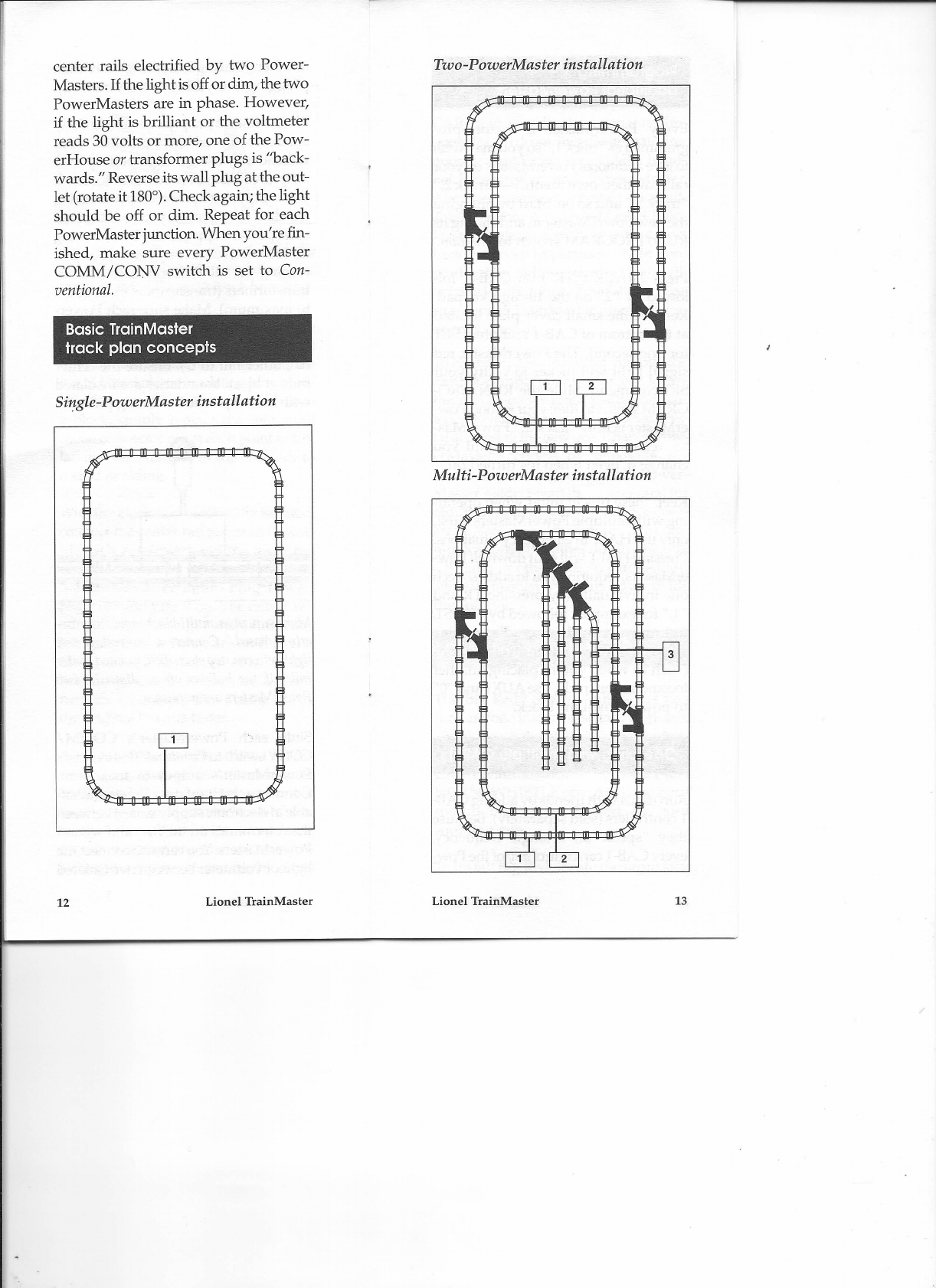
Every PowerMaster is factory-pro-
grammed as track I, so you may wish
to give additional PowerMasters on your
railroad their own identity- track 2,
track 3, and so on. Start by plugging
the new PowerMaster in and sliding its
RUN /PROGRAM switch to
Program.
Keep these tips in mind when operat-
ing with multiple PowerMasters. First,
only use HALT in emergency situations.
Pressing HALT will shut down
all
Pow-
erMasters, requiring you to address each
one individually (by pressing TR and
I, for example), followed by BOOST,
to turn each one back on. For routine
stops or simple power off situations
(such as when you're placing another
locomotive on track), use AUXI and 0
to power down the block.
Operating with Big Red®
Run trains with friends by adding CAB-
1controllers (sold separately). Because
they speak on a single frequency,
every CAB-I can control
any
of the Pow-
The Big Red® control button lets you
turn anyone into an assistant engineer.
Simply touch the pressure-sensitive but-
ton, and the last command issued by
CAB-I is automatically repeated. Press
HORN /WHISTLE on CAB-I; the horn
sounds. Next, press Big Red. The horn
sounds again.
Operating with multtiple CAB-l s
Toinstall Big Red, locate the input jack
14
Lionel TrainMaster Lionel TrainMaster
15

III,.
Is CAB-l speaking to PowerMaster?
Press TRACK, 1 on the Ill-digit key-
pad, then any command button. This
reestablishes communication with any
factory-programmed PowerMaster.
III,.
Press BC:X:>ST;this reactivates a shut-
down PowerMaster.
Turn off any interfering electronic
devices in your railroad area: televisions,
computers, and CB radios.
Relocate PowerMaster to a more
accessible location in your train area.
III,.
Reprogram PowerMaster. Slide the
RUN / PROGRAM switch to
Program.
Press TRACK ( TR ) and your num-
ber choice from the la-digit keypad.
Slide the switch back to RUN. Press TR,
the number, and DIRECTION; Power-
Master should respond with a flashing
red light.
III,.
Check the frequency crystals inside
CAB-l and PowerMaster. They should
be installed with a snug fit.
Plug Big Red's wire into the jack located
on the top ofCAB-l.
on the top edge of CAB-l and plug in
Big Red's wire. You're now ready for
Big Red locomotive operations.
Answers to questions
THE GREEN LIGHT
IS
OFF
III,.
Plug in PowerHouse and turn it on.
Check PowerHouse's circuit breaker'
push it in if it's been triggered. '
Make sure PowerHouse's connect-
ing wire is secured
firmly
in Power-
Master's input. PowerMaster's green
light should illuminate.
I
WANT TO PUT ANOTHER LOCO-
MOTIVE
ON
TRACK
Address the block of track your loco-
motive will occupy. Deactivate it by
pressing AUXI and 0 on the Ifl-digit
keypad. Reestablish power by pressing
BOOST.
III,.
The stall voltage should be checked
and reset if necessary.
THE GREEN LIGHT
IS
FLASHING
11,* There's a' short-circuit across the
track PowerMaster is controlling.
Check for derailments or other short cir-
cuits. Reset PowerMaster by pressing
BOOST.
THE RED LIGHT DOESN'T FLASH
III,.
Check the alkaline batteries in CAB-
1for freshness and proper installation.
When CAB-l isproperly powered, you'll
hear a small clicking sound with every
button press.
III,.
Extend the telescoping antenna com-
pletely.
THE LOCOMOTIVE WON'T MOVE
111I. CAB-l may be asleep. Press BOOST.
1111. Check the connections between
PowerMaster and your track. TheAwire
should connect to the center rail; the U
wire attaches to an outside rail.
III,.
If your locomotive derailed, Pow-
erMaster's short-circuit protection may
have been activated. When PowerMaster
16
Lionel TrainMaster Lionel TrainMaster
17

senses a major overload, it momentar-
ilywaits before shutting down. Aquickly
remedied problem won't trip Power-
Master's circuitbreaker. However, a con-
tinuing short will cause PowerMaster
to shut down for a second, then retry.
Ifthe short remains, PowerMaster turns
itself off and flashes its green light.
Remove the short and press BOOST.
WHAT ARE ALL THESE
OTHER BUTTONS FOR?
~ Good question. When the digital
TrainMaster Control Base is released,
CAB-I's currently unused buttons will
be integral to your further enjoyment
of Lionel trains. Don't worry that the
system you just purchased will be obso-
lete-nothing could be further from real-
ity.The truth is,your Lionel TrainMaster
system today is ready for the digital rev-
olution of tomorrow. Stay tuned.
TrainMaster technical support
We want your experience with Lionel
TrainMaster to·be the best. If you've
been through Answers to questions
and still can't get your Lionel Train-
Master system operating to your satis-
faction, please call our TrainMaster
technical support line.
1 800 727 7297
Monday through Friday,
8 a.m. to 5 p.m. Eastern Time
18
Lionel TrainMaster
This manual suits for next models
1
Table of contents
Other Lionel Remote Control manuals