Lipco GSG-S-VM User manual
Translation of
Saddle-mount unit GSG-S-VM
original instructions
One- / two- / three row
LIPCO GmbH
Am Fuchsgraben 5b
D-77880 Sasbach
Tel.
+49 7841 6348-0
Fax
+49 7841 6348-300
E-mail
Web
www.lipco.com
Picture shows an example of assembly on a Braud harvesting ma-
chine.
Note: this manual will also apply to assembly on Gregoire Harvester.

Instructions
Saddle-mount unit GSG-S-VM
2 - 72
010710-03-EN BA GSG-S-VM / 13.07.2020

Instructions
Saddle-mount unit GSG-S-VM
3 - 72
010710-03-EN BA GSG-S-VM / 13.07.2020
1. Introduction
Dear Customer:
Thank you for choosing a LIPCO Saddle-mount unit GSG-S-VM. We
are confident that you will be satisfied with our product.
In order to achieve maximum performance from your new LIPCO
Saddle-mount unit GSG-S-VM over an extended period, please fol-
low the instructions in this operating manual closely. This will help
you to prevent any damage and to prevent accidents that could re-
sult from failure to comply with the manual and for which LIPCO can
assume no liability.
This operating instruction is an essential component of the machine
and therefore must always be included when the machine is sold, al-
so if it is sold to third parties.
By carefully storing the operating manual in a safe place, both you
and the operator will have a comprehensive reference work at hand.
Note:
The illustrations, descriptions and data contained in these instruc-
tions are not binding. LIPCO reserves the right to make changes at
any time, without prior notice.
This manual applies only to the LIPCO Saddle-mount unit GSG-S-
VM and does not replace the operating instructions for components,
built-in by the customer.
For specific points (like maintenance etc., ) concerning the BRAUD-/
Gregoire- or Pellenc harvester , please refer to the instructions of the
adequate harvester supplier.

Instructions
Saddle-mount unit GSG-S-VM
4 - 72
010710-03-EN BA GSG-S-VM / 13.07.2020
2. Content Page
1. Introduction..................................................................................... 3
2. Content ........................................................... 4
3. Authorized use................................................................................ 6
4. Warnings on the machine............................................................... 8
5. General safety regulations.............................................................. 9
6. Safety information for handling plant protection agents ................ 10
7. Accident prevention ...................................................................... 11
8. Design details of the GSG-S-VM - standard equipment................ 12
9. Design details of the GSG-AN-VM - special equipment................ 13
10. Advantages of LIPCO tunnel spray technology ............................ 13
11. Technical data GSG-S-VM ........................................................... 14
12. Technical data fan unit.................................................................. 15
13. Components of GSG-S-VM .......................................................... 16
13.1. Filters............................................................................................ 16
13.2. Hydraulic row width adjustment .................................................... 17
13.3. Cross flow fan height adjustment.................................................. 19
13.4. Tanks of GSG-S-VM:.................................................................... 20
13.5. The different valves of the GSG-S-VM:......................................... 21
14. Preparation ................................................................................... 23
15. Mounting GSG-S-VM on harvester............................................... 24
16. Driving on roads with the GSG-S-VM2 ......................................... 26
17. Operating the GSG-NV-VM .......................................................... 27
17.1. Determining the amount of spray liquid needed............................ 27
17.2. Checking the driving speed........................................................... 27
17.3. Calculation of the driving speed.................................................... 28
17.4. Nozzle selection and distribution quantity..................................... 29
17.5. Checking the liquid discharge....................................................... 31
17.6. Nozzle adjustment during operation.............................................. 34
17.7. Spray nozzle adjustment............................................................... 35
17.8. Worth knowing about proper nozzle adjustment........................... 36
17.9. Adjustment of outer fan................................................................. 37
17.10. RPM fan setting ............................................................................ 38
17.11. Recycling device........................................................................... 39
18. Setting the GSG-S-VM.................................................................. 42
18.1. Calculation of the liquid discharge ................................................ 42
18.2. Calculation of the required plant protection agent/spray............... 43
18.3. Intervals for checking the dosing and distribution accuracy.......... 44
of the GSG-S-VM.......................................................................... 44
18.4. Which plant protection agents can be used in the......................... 44
GSG-AN-VM?............................................................................... 44
19. Spray test...................................................................................... 45
20. Preparation of spraying liquid..............................................46
21. Instructions for working with crossflow fans ........................48
22. Emptying the GSG-AN-VM2 after use.................................50
23. Residual volume ..................................................................50

Instructions
Saddle-mount unit GSG-S-VM
5 - 72
010710-03-EN BA GSG-S-VM / 13.07.2020
24. Interruption of spraying process..........................................51
25. GSG-S-VM cleaning after use.............................................53
26. Maintenance ........................................................................56
27. Machine inspection..............................................................60
27.1. Pressure check....................................................................60
27.2. Flow rate check....................................................................60
28. Troubleshooting...................................................................62
29. Machine storage ..................................................................64
30. Disposal of GSG-S-VM........................................................66
31. Warranty ..............................................................................67
32. Functional diagram GSG-S-VM...........................................68
33. Wiring diagram for GSG-S-VM (hydraulical / electrical)......69
34. Notices.................................................................................70
35. EC Declaration of conformity...............................................71

Instructions
Saddle-mount unit GSG-S-VM
6 - 72
010710-03-EN BA GSG-S-VM / 13.07.2020
3. Authorized use
LIPCO GSG-S-VM saddle-mount unit GSG-S-VM is available as a
single-row / two-row or three-row version.
LIPCO saddle-mount unit GSG-S-VM (one-row version with recycling
technology and assembly on the adequate harvester) is designed for
one-row treatment with crop protection agents in viticulture, rose and
berry cultivation and similar cultures.
LIPCO saddle-mount unit GSG-S-VM (two-row version with recycling
technology and assembly on the adequate harvester) is designed for
two-row treatment with crop protection agents in viticulture, rose and
berry cultivation and similar cultures.
LIPCO saddle-mount unit GSG-S-VM (three-row version with recy-
cling technology and assembly on the adequate harvester) is de-
signed for three-row treatment with crop protection agents in viticul-
ture, rose and berry cultivation and similar cultures.
Note!
LIPCO saddle-mount units GSG-S-VM are Julius-Kühn Institute
Braunschweig / Germany (JKI) approved and registered in the list of
loss-reducing devices. For classification and authorized use please
refer to actual folder „Verlustmindernde Geräte“
(www.jki.bund.de/geraete“)
Technical modifications without any written agreement, either by
LIPCO or by JKI, are not allowed. Otherwise LIPCO saddle-mount
units GSG-S-VM will lose its classification as loss-reducing device
and will release the manufacturer from liability for resulting damages.
Any other use will be considered as not authorized. The manufactur-
er will not be liable for damages resulting from unauthorized use; the
user will be solely responsible for all risks in this case.
Authorized use also includes compliance with the manufacturer’s
operating, maintenance and repair instructions.
The operator is responsible for compliance with applicable accident
prevention regulations, in addition to the generally recognized safety,
occupational health and traffic safety regulations.

Instructions
Saddle-mount unit GSG-S-VM
7 - 72
010710-03-EN BA GSG-S-VM / 13.07.2020
Note for use on public roads:
For driving on public roads and paths, make sure that the combina-
tion of harvester and LIPCO saddle-mount units GSG-S-VM or other
combined equipment complies with the applicable traffic regulations
(maximum gross weight, maximum axle loads, lights, warning signs,
etc.).
Note:
Following this operating instruction will use the abbreviation GSG-
S-VM instead of LIPCO saddle-mount unit GSG-S-VM.
Instructions
Saddle-mount unit GSG-S-VM
8 - 72
010710-03-EN BA GSG-S-VM / 13.07.2020
4. Warnings on the machine
Before operating the machine, always read the oper-
ating manual and comply with all safety instructions!
Always shut off the motor and remove the ignition
key when performing maintenance or repairs!
Danger of parts being catapulted while drive unit is in
operation –maintain safety clearance!
Operate machine only at the specified speed (max.
540 rpm)!
Danger of poisoning - never climb into the spray liq-
uid tank!

Instructions
Saddle-mount unit GSG-S-VM
9 - 72
010710-03-EN BA GSG-S-VM / 13.07.2020
5. General safety regulations
The operation of mobile plant protection units is associated with cer-
tain risks. Therefore, you must comply with the following safety regu-
lations:
•Before operating the machine, always read the operating manual
and comply with all safety instructions!
•Never remove or modify safety devices!
•Secure the area beneath the machine for repairs or inspections!
•Switch off the machine prior to performing maintenance or care!
•Always maintain safety clearances!
•Note! Do not enter the work area while the universal joint shat is
rotating! There is an increased risk of accident in case of contact.
For your safety, do not wear loose clothing or accessories (e.g.
scarves)!
•Operate, maintain or repair the GSG-S-VM only by especially
trained personnel who are aware of the risks involved!
•The operator is responsible for compliance with applicable acci-
dent prevention regulations, in addition to the generally recog-
nized safety, occupational health and traffic safety regulations!
•The warning and information signs on the machine provide im-
portant information for safe operation; compliance with these
warnings will increase your safety!
•Persons not involved must keep out of the work area of the ma-
chine.
•Keep children away from the GSG-S-VM and spray.
•Operate machine only at the specified speed
(max. 540 rpm)!

Instructions
Saddle-mount unit GSG-S-VM
10 - 72
010710-03-EN BA GSG-S-VM / 13.07.2020
6. Safety information for handling plant protection agents
•Do not use plant protection agents that tend to gum up or con-
geal –they have a negative effect on spraying.
•Before applying heat (welding, soldering, etc.) in order to repair
the tunnel spray unit or attachments,
•Clean tunnel spray unit or attachments, which were in contact
with plant protection agent, thoroughly with water, before apply-
ing heat (welding, soldering…)
•Do not remove or modify standard safety devices!
•Replace damaged safety devices by new ones.
•Replace damaged seals and shut-off devices!
•People in contact or working with plant protection agent have to
wear suitable protective clothing against contamination! (e.g.
safety gloves…)
•Always comply with the regulations of the phytosanitary manu-
facturer and of the trade association. AID brochure 1042 (2) pro-
vides information on the safe handling of plant protection agents.
Relevant literature is available by:
Evaluation and information service for nutrition, agriculture and
forestry (AID), P.O. Box 20 02 53, 53173 Bonn.
AID brochure 2079 (1):
Filling of phytosanitary: Note in taking water from the drinking
water supply and public waters.
AID brochure 1042 (2):
Note in handling herbicides and plant protection agents.
•Do not eat, drink or smoke when working with herbicides and
plant protection agents.
•Wash hands and face thoroughly with soap and water after every
contact with spraying equipment or spray liquid and after com-
pletion of work.

Instructions
Saddle-mount unit GSG-S-VM
11 - 72
010710-03-EN BA GSG-S-VM / 13.07.2020
7. Accident prevention
Failure to comply with the simplest basic rules are causing most ac-
cidents occurring during use, maintenance or transport.
Therefore, it is important that all persons involved with use of the
machine are aware of and comply with the following rules:
•In order to achieve maximum performance from the GSG-S-VM
it must be in proper working condition. Perform maintenance and
repair only by trained people.
•Replacement parts must fulfill the minimum technical specifica-
tions required by the manufacturer! Only use of LIPCO original
replacement parts will fulfill these requirements.
•Before each use, check the trailer hitch bolts on the three-point
mount and all studs and nuts!
•Exercise special Note when using roads or paths, e.g. for turning
the entire tunnel spray unit.
•Always shut off the motor and remove the ignition key when per-
forming maintenance or repairs!
•During work and transport on public road, do not transport ob-
jects or persons on the machine!
•Operate machine only with drive unit fully protected, i.e. univer-
sal joint shaft completely covered and additional protection on
tractor and GSG-S-VM. Make sure that the universal joint shaft
connections lock securely into place!
•The machine should be on a level surface or a stable support
during all work on the machine!
When working on the machine in raised position, always secure
by mechanical means using suitable supports!

Instructions
Saddle-mount unit GSG-S-VM
12 - 72
010710-03-EN BA GSG-S-VM / 13.07.2020
8. Design details of the GSG-S-VM - standard equipment
•frame with double-coat paint RAL 6011 (green)
•hydraulic sliding mechanism of outer tangential fan for desired
row spacing (common or single function); inner tangential fan
unit dimension can be adjusted mechanically via a chain; middle
tangential fan unit is permanently mounted
•fitting: 1 electric pressure control valve for pressure adjustment,
3 electric motor valves for fan switching (can be controlled sepa-
rately or together), 2 electric motor valves for agitator and suc-
tion (can be controlled separately)
•2x double-acting electric control block for tangential fan unit ad-
justment (outer tangential fan unit –separate or common adjust-
able)
•6 hydraulic driven tangential fans, equipped with collecting tray
and hydro injector for the leading back of the unused liquid - min-
imum operating pressure 5 bar required for suction
•one V4A nozzle tube integrated in each fan, each with 6 drip-
stop rotary nozzle bodies with flat fan venturi nozzles (IDK 90°
green –or other spray output on request) –individually adjusta-
ble
•pressure (80 mesh), suction (50 mesh) and recycling insert for
basket filter (80 mesh)
•2x 1000-liter tanks with tank cleaning nozzle and injector agita-
tor, water jet mechanism integrated in filling screen
•3-way tap with quick-release coupler and 2.50 m hose for exter-
nal suction
•full electrical control: Nozzles, pressure and recycling can be
controlled via control box on tractor (mounted to right of driver),
digital pressure indicator
•Upper side-mounted pump, 250 l, 20 bar, driven with oil motor.
Pump mounted to tanks to enable constant emptying. Pump can
be switched to 200 l freshwater tank for machine cleaning
•15 l freshwater tank for hand washing
•4 parking supports for secure parking of the unit

Instructions
Saddle-mount unit GSG-S-VM
13 - 72
010710-03-EN BA GSG-S-VM / 13.07.2020
9. Design details of the GSG-AN-VM - special equipment
•Center fan unit overall width 3,15 m
•Rear attached fan unit overall width 2,85 m
•Row width 3.20 instead of 2.50 m
•Row width 1,30 m instead of 1,10 m –only outer tunnel
•2 x 1500 l tank instead of 2 x 1000 l tank
•External spray agent mixer for transferring mixture to
•tank, including container cleaning nozzle and suction pistol, 50 l
•LED working lights between fans
•Electrical monitoring and control unit, with digital display, incl. on
board computer and boom section switches
•Other nozzles
•2 agent-sprayer type BS 2
10. Advantages of LIPCO tunnel spray technology
•The fan design causes a higher spray concentration and there-
fore a more intensive deposition of spray on the plants.
•Natural wind outside the fan has nearly no negative influence on
spraying result.
•Non-deposited spray will be collected in a pan and filtered for re-
use.
•The spray nozzles can be switched on and off depending on the
height of the foliage wall for optimum use of spray.
•The fans guarantee enough air flow. They are arranged in a way,
that suction side of one fan is opposite to the pressure side of
the opposite fan.
Instructions
Saddle-mount unit GSG-S-VM
14 - 72
010710-03-EN BA GSG-S-VM / 13.07.2020
11. Technical data GSG-S-VM
GSG-S-VM
one row
GSG-S-VM
two row
GSG-S-VM
three row
Row height
m
2,20
2,20
2,20
Weight –standard version
(without harvester)
kg
2300.-
Pump type
AR 230 bp
AR 230 bp
AR 230 bp
Fan pairs
1
2
3
Row width (standard)
m
1,80 –2,50
Fan width
m
0,20 –1,10
Pump output max.
250 l./min
at 16 bar / 540 rpm
Tank size (standard)
2 x 1000 l
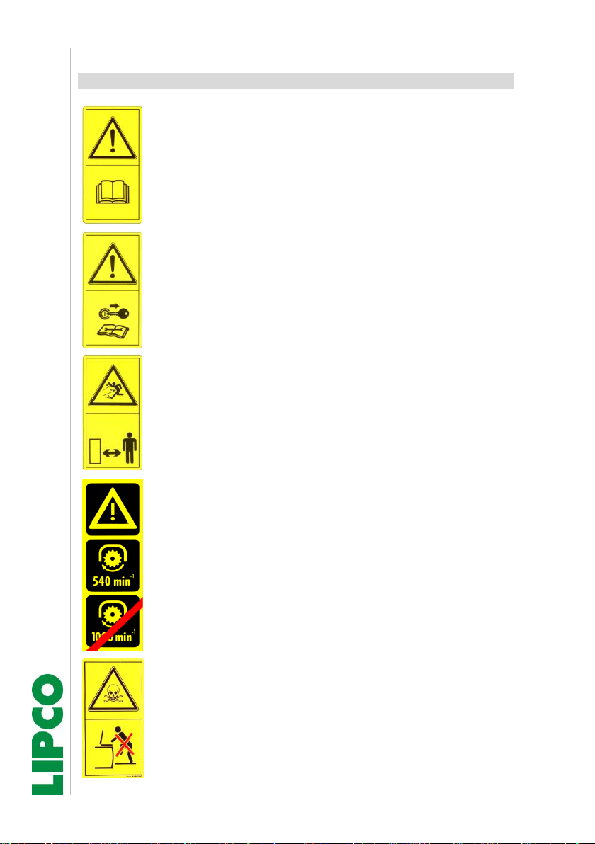
External main dimensions:
L (m)
B (m)
GSG-S-VM
0,40
3,50
Note:
•Pay attention to possible lateral projection of the driver's cab be-
yond the GSG-S-VM –fans retracted to smallest width!
•Other dimensions of the GSG-S-VM are within the main dimen-
sions of the harvester. For the main dimensions of the harvester
please refer to harvester’s instructions.

Instructions
Saddle-mount unit GSG-S-VM
15 - 72
010710-03-EN BA GSG-S-VM / 13.07.2020
12. Technical data fan unit
The fan units require a maximum oil quantity of 16 l/min at max. 150
bar. The crossflow fan are driven by the hydraulics of the harvester.
The tractor should be equipped with an oil flow regulator so that the
air volume can be regulated.
Oil flow regulator is available at LIPCO.
Nominal volumetric flow/cross flow fan:
This is measured in the free air flow at 0.6 m distance from air flow
outlet of cross flow fan:
Fan length - (m)
RPM
Air speed
(m/sec.)
Nominal volumetric
flow (m³)
2,5
800
6
2,5
1000
8
2,5
1200
10
2,5
1400
12
3,0
800
3,0
1000
3,0
1200
3,0
1400

Instructions
Saddle-mount unit GSG-S-VM
16 - 72
010710-03-EN BA GSG-S-VM / 13.07.2020
13. Components of GSG-S-VM
13.1. Filters
Suction filter 50 mesh = 0,297 mm:
•Suction filter on top of spray
liquid tank.
The filter insert should be
checked several times daily for
dirt and cleaned, if necessary
Fig. 1
Pressure filter 50 mesh = 0,297 mm:
•The pressure filter is located
between the shutoff motors.
•The quick cleaning unit in lower
end of the pressure filter is
connected to hydro injector in
tank and permanently pressur-
ized.
Drain valve must be perma-
nently open.
Fig. 2
•This circuit guarantees an extended cleaning cycle.
•More pressure filters are integrated in the spaying nozzles.
•These nozzles filters should be checked by the end of the spay-
ing procedure and cleaned if necessary.
Instructions
Saddle-mount unit GSG-S-VM
17 - 72
010710-03-EN BA GSG-S-VM / 13.07.2020
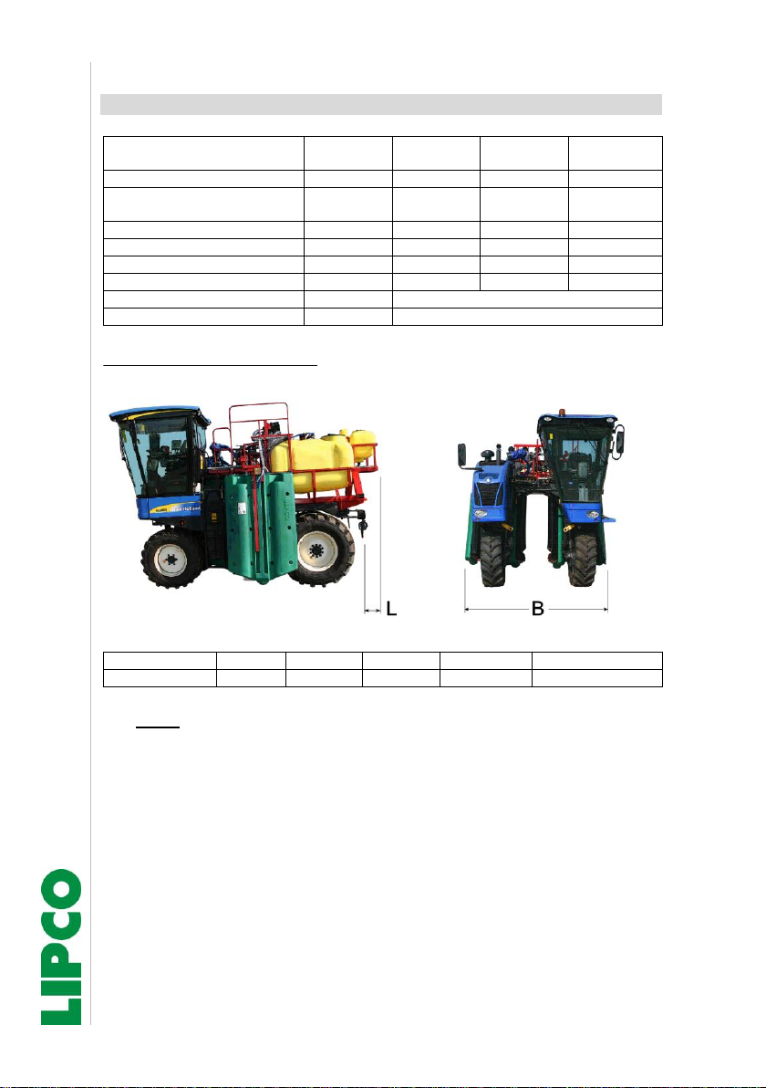
Recyclingfilter –80 mesh:
•The recycling filters are located
on top of the spray liquid tanks.
(Fig. 3)
The recycling filters in the re-
turn flow of the recovered spray
liquid must be checked several
times a day and cleaned if nec-
essary.
Fig. 3
13.2. Hydraulic row width adjustment
•The width is adjusted via con-
trol box from the operator's cab
of the harvester. (Abb. 4)
Hydraulic cylinder for width ad-
justment.
Fig. 4
4
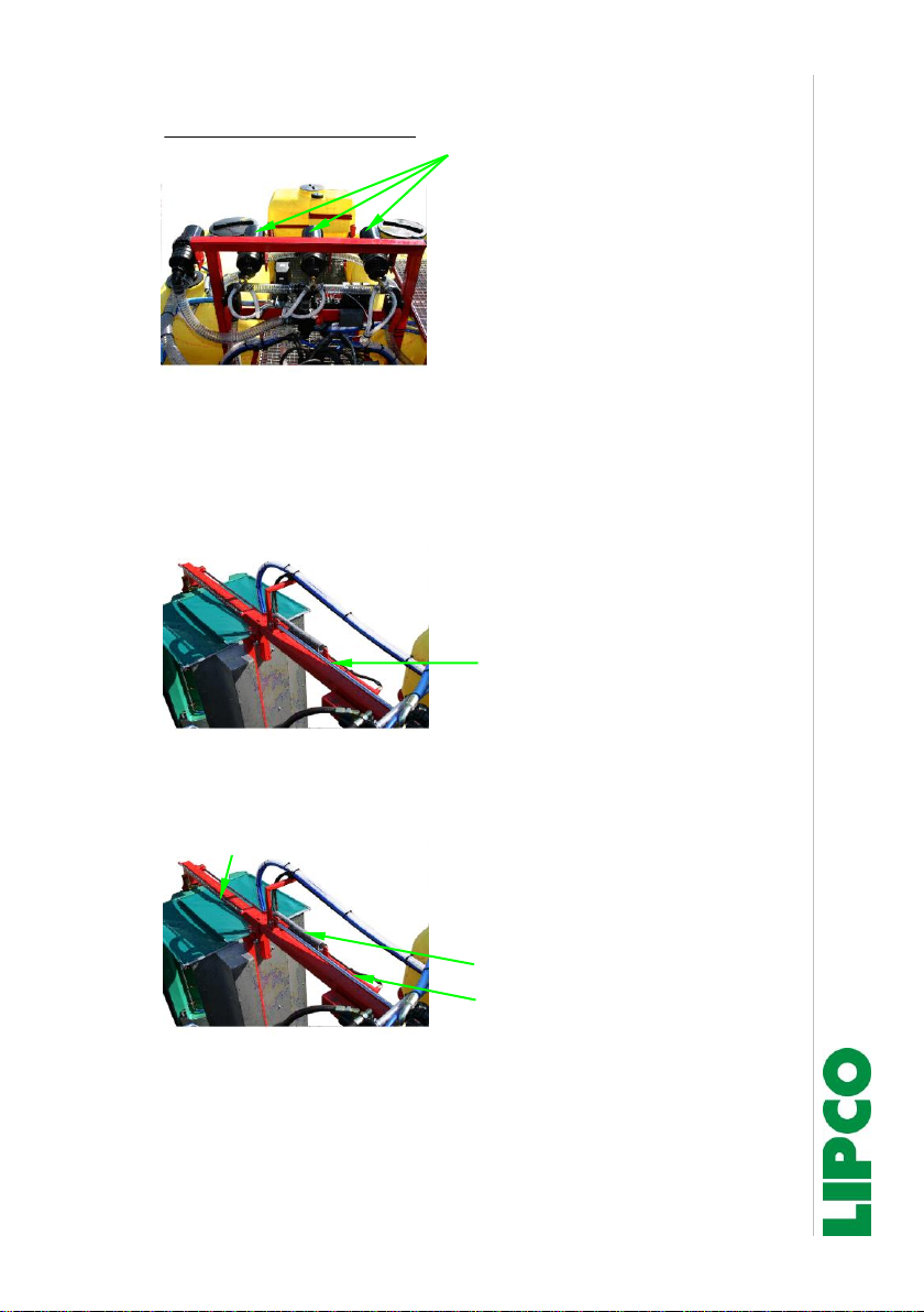
•The tension springs on the top
of saddle-mount unit will retract
the inner cross flow fans when
the width is adjusted. Fig. 5)
Tension spring
Hydraulic cylinder
Fig. 5
Kette
Chain
Instructions
Saddle-mount unit GSG-S-VM
18 - 72
010710-03-EN BA GSG-S-VM / 13.07.2020
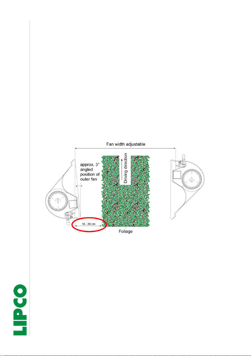
•The chain is used to adjust the width of a fan pair.
When the outer fans are extended with the hydraulic cylinder, the
attached chain takes the inner crossflow fan with it. The tension
spring is tensioned at the same time.
When the hydraulic cylinder is retracted, the previously ten-
sioned tension spring of the inner crossflow fan returns to its ini-
tial position.
For different widths, the chain must be rehooked at the outer
hook depending on the desired width.
•Set the chain to a length, that distance between nozzles and foli-
age is about 16 –26 cm. See below.

Instructions
Saddle-mount unit GSG-S-VM
19 - 72
010710-03-EN BA GSG-S-VM / 13.07.2020
Spray mist catcher:
•Narrow cross flow fan position
during spraying before blos-
soming has a positive effect on
the return quantity.
However, contact with the
young shoots must be avoided.
(Fig. 6)
Spritznebelfänger
Fig. 6
13.3. Cross flow fan height adjustment
Mechanical height adjustment: standard version
•The height is adjusted manually
via spindle. (Fig. 7)
After adjustment, counter the
locking plate again!
•Note max. dimension 690 mm!
Fig. 7

Instructions
Saddle-mount unit GSG-S-VM
20 - 72
010710-03-EN BA GSG-S-VM / 13.07.2020
13.4. Tanks of GSG-S-VM:
Spray liquid tank / freshwater tank / handwash tank:
Freshwater tank: (Fig. 8)
This tank contains the fresh wa-
ter for cleaning the machine af-
ter the end of the spraying pro-
cess.
Spray liquid tank (2x)
Fig. 8
•Do not fill the spray liquid tanks beyond the nominal volume –
see volume level indicator. The remaining volume is used for ab-
sorption in the event of excessive foam formation.
•All pipes, valves, pump and tank can be cleaned with the water
from the flushing water tank.
•Pay Note to required valve positions, see section 21.
•Note:
Do not fill freshwater tank with spray liquid!
Do not drink out of freshwater tank!
Handwash tank:
Handwash tank located next to
freshwater tank
(Fig. 9)
•Fill handwash tank only with
clean freshwater to clean the
hands after spray operation.
Fig. 9
Table of contents
Popular Car Seat manuals by other brands


Britax
Britax PEGASUS DLX manual

BEBE CONFORT
BEBE CONFORT 2wayPearl Instructions for use & warranty

KIDDY
KIDDY GUARDIANFIX PRO 2 - Directions for use

gb PLATINUM
gb PLATINUM CONVY-FIX FUTURE PERFECT manual

Plush
Plush TUSH TUSH001 User instructions

RECARO
RECARO Expert plus Reha Instructions for assembly and use