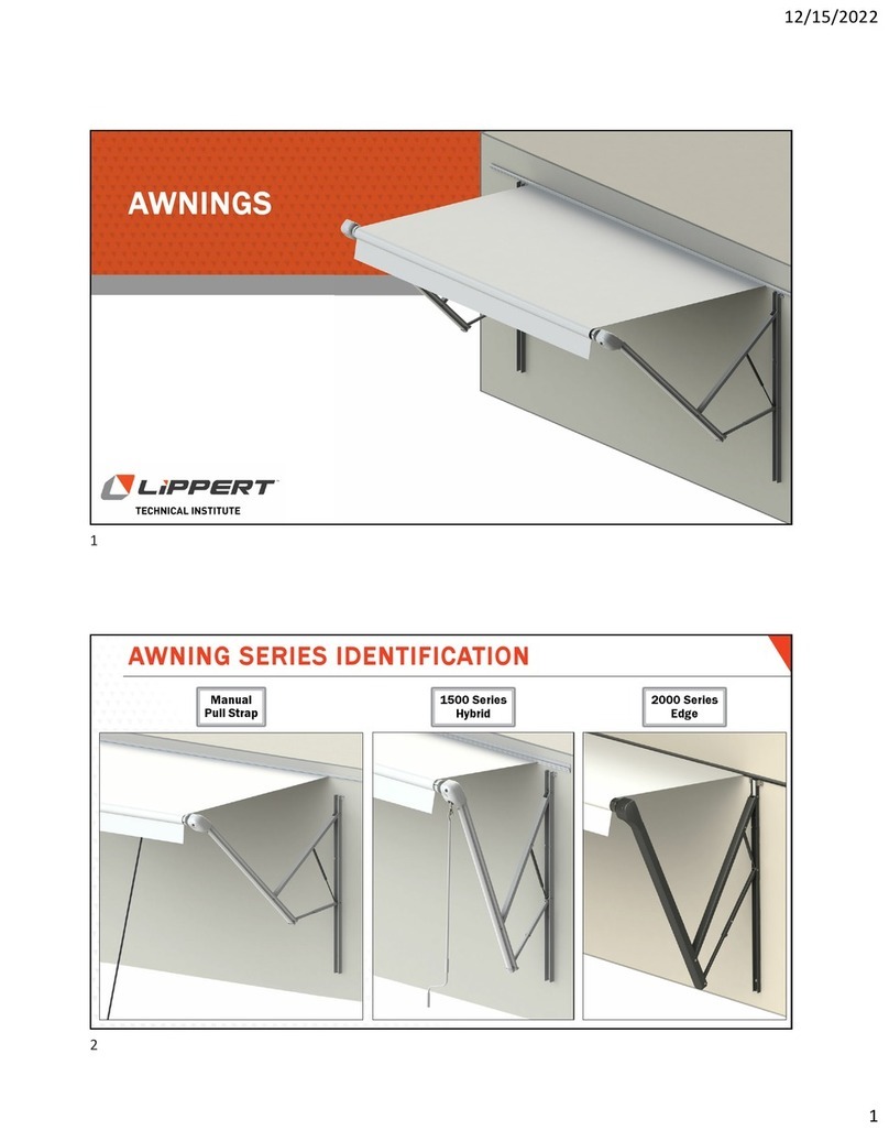
Lippert Girard GG750 Setup guide

Girard GG750 Awning
with Solar Station for
Residential housing
INSTALLATION SERVICE
AND REPAIR MANUAL

Rev: 05.10.2023 Page 2 CCD-0007494
TABLE OF CONTENTS
Introduction 3
Safety 3
Resources Required 4
Basic System Overview 5
Mechanical System Components 5
Electronic Controls 5
User Controls 5
Installation Manual 6
Unpacking 6
Layout And Mounting The Brackets 6
Bracket Placement Chart 7
Install Mounting Brackets 7
Mounting The Awning 9
Weather Stripping (Option - Not included - Sidewall Application ONLY) 9
Electronic Controls Installation 10
Solar Panel - 2022304364 10
Motion Sensor - 2022304365 10
Solar Station Programming 10
Testing And Adjustments 11
Overview 11
Adjusting Motor Limit Switches 11
Adjusting Pitch And Elbow Height 12
Manual Override 12
Testing The Motion Sensor (Wind Sensor) 14
Adjusting The Lead Rail 14
Troubleshooting Guide 14
Common Repair Procedures 16
Motor Replacement 16
Fabric Replacement 17
Arm Replacement 18
GG750 Exploded View 19
GG750 Component Identication 20
Notes 21
Introduction
The GG750 awning system provides protection from the sun at a touch of a button. The GG750 Solar Awning
is built to specifications with the highest quality materials available, the unit features:
• A 12VDC motor that operates with the Girard Solar Station.
• Motion sensor that will retract the awning to prevent damage from the wind.
• A hand held remote control.
The Solar Station awning controls use an RF (radio frequency) link to communicate with each other. This
simplifies the installation and maintenance by removing the need for any wiring.

Rev: 05.10.2023 Page 3 CCD-0007494
Failure to follow instructions provided in this manual may result in death, serious personal injury
and/or severe product and property damage, including voiding of the component warranty.
The "WARNING" symbol above is a sign that a procedure has a safety risk involved and may cause
death or serious personal injury if not performed safely and within the parameters set forth in this
manual.
Safety
Read and understand all instructions before installing or operating this product. Adhere to all safety labels.
Local building codes may impose additional requirements that may supersede the installation instructions
in this manual. Be sure to check with the local municipality for code adherence. Determining the
acceptability of alternate installation methods is solely the responsibility of the installer.
This manual provides general instructions. Many variables can change the circumstances of the instructions,
i.e., the degree of difficulty, operation and ability of the individual performing the instructions. This
manual cannot begin to plot out instructions for every possibility, but provides the general instructions,
as necessary, for effectively interfacing with the device, product or system. Failure to correctly follow the
provided instructions may result in death, serious personal injury, severe product and/or property damage,
including voiding of the Lippert limited warranty.
Be sure turn o power before beginning any electrical work. All electrical work must be carried out
by qualied personnel and conform to applicable electrical codes and standards. Please consult the
wiring diagram to locate any wiring prior to any drilling or any installation procedures.
Additional information about this product can be obtained from lci1.com/support or by downloading
the free LippertNOW app. The app is available on Apple App Store® for iPhone® and iPad® and also on
Google Play™ for Android™ users.
Apple App Store®, iPhone®, and iPad® are registered trademarks of Apple Inc.
Google Play™ and Android™ are trademarks of Google Inc.
For information on the assembly or individual components of this product, please visit:
https://support.lci1.com/gp-llc-awnings-manuals.
NOTE: Images used in this document are for reference only when assembling, installing and/or operating
this product. Actual appearance of provided and/or purchased parts and assemblies may differ.
Always wear eye protection when performing service, maintenance or installation procedures.
Other safety equipment to consider would be hearing protection, gloves and possibly a full face
shield, depending on the nature of the task.
The “CAUTION” symbol above is a sign that a safety risk is involved and may cause personal injury
and/or product or property damage if not safely adhered to and within the parameters set forth
in this manual.

Rev: 05.10.2023 Page 4 CCD-0007494
Basic System Overview
Mechanical System Components
1. The enclosure (or cassette) protects the awning while closed.
2. The roller tube which is mounted within the cassette.
3. The top cover or fabric rolled onto the roller tube and connected to the lead rail that extends from the
enclosure when the awning is opened.
4. The folding arms that supports the lead rail and the fabric.
5. Tubular motor - (2022304366), mounted inside of the roller tube that controls the extension and
retraction of the awning.
Electronic Controls
1. To power and operate the motor.
2. Motion Sensor – 2022304365, which enables automatic retraction of the awning during periods of high
wind that may damage the awning system.
3. Solar Panel - 2022304364.
Resources Required
• Cordless or Electric Drill or Screw Gun
• Tape measure
• Ladders (2)
• Chalk line
• Flat head screwdriver (small)
• Phillips screwdriver
• Caulking gun
• (2) tubes silicone caulking
• Drill bits: 1/8”, 3/8”, 7/16”, 1/4”
• Hex wrenches: 4mm
• Open-end wrenches: 19mm, 17mm
• Ensure that placement of controls, cables, and wires are not in any way obstructed. This can damage the
components and obstruct electrical current.
• Use only certified components.
Girard Systems awnings may be operated in light wind and rain conditions. When periods of heavy rain and or
high wind are expected the awning must be closed. Never leave the awning open and unattended.
Damage caused by wind and rain is not covered by warranty.
If applicable, all awnings must be closed prior to moving the vehicle for any reason. As an extra safety
precaution a visual check that every awning is fully closed is required.
Damage caused by failure to comply with these instructions is not covered by warranty.
Before using the awning, ensure that the area into which the awning will be deployed is free of obstructions
(Trees, walls, pillars, posts, other vehicles etc.).
Damage caused by collisions with any of the above or similar is not covered by warranty.
To prevent the motor from overheating do not exceed 4 minutes of operation per hour.
Overheating will destroy the motor.
Ensure that placement of controls, cables, and wires are not in any way obstructed. This can damage
the components and obstruct electrical current.
Use only certied components.

Rev: 05.10.2023 Page 5 CCD-0007494
User Controls
1. 2022304368 – Single Channel Awning Remote Control.
Installation Manual
Unpacking
Before starting any of the installation procedures unpack the awning and inspect the product for any
possible damage that may have occurred during shipping.
1. Before starting any of the installation procedures ensure that the length and fabric of the awning are correct.
2. When you have determined the awning position, remove the mounting brackets and place the awning in a
safe location while preparing the mounting surface.
A. To remove the brackets. Locate the slide lock that retains the bracket to the housing, (Fig. 1).
B. Using a 4mm hex wrench, loosen the set screws on the slide locks.
C. Once the set screws have been loosened the slide locks should slide freely. Clear the slide lock
away from the bracket.
D. You should now be able to remove the bracket.
3. If any damage or missing parts are discovered, please contact the supplier.
For personal safety and quality of installation, two installers are recommended for this product.
Layout And Mounting The Brackets
NOTE: Please take into consideration all possible clearances, and obstacles before installing this awning.
Please consult Girard by Lippert if there are any questions regarding the installation.
A. The mounting brackets can accommodate ¼” lag bolts for mounting.
B. Determine the location for the final installation position of the awning, including height to be
installed.
C. Mounting brackets must be installed at the locations shown in bracket placement diagram, (Fig. 2).
NOTE: When installing a three-arm awning, make sure one of the applicable center brackets is directly
behind the shoulder of the middle arm.

Rev: 05.10.2023 Page 6 CCD-0007494
D. To determine bracket mounting locations, use
an electronic stud finder and a non-permanent
pen or pencil.
E. Move the stud finder horizontally along the
height or the awning location, marking the
stud locations and avoiding any electrical
wiring.
F. Using one of the brackets as a guide, mark
the locations on the wall that match the
placement labels on the back of the awning.
NOTE: At least two of the lag screws must be set into
a stud to provide strength and support for the
mounted awning, (Fig. 4). The location of the
stud may not align perfectly with the label. Be
sure to secure the bracket to the closest stud.
Repeat for each label location.
G. For longer awnings, additional brackets can be
mounted to provide extra support. Locate and
mark these bracket locations, evenly spaced
between the main brackets.
H. If the stud is not within 6” of the original bracket location, place an additional bracket on that
location as additional support against torquing and twisting of the case.
NOTE: Depending on the length of the awning, there could be up to 7 brackets utilized.
NOTE: These brackets should also have a minimum of two lag screws fastened into studs, (Fig. 4).
Fig. 1

Rev: 05.10.2023 Page 7 CCD-0007494
Bracket Placement Chart
Install Mounting Brackets
Failure to follow these instructions will void the warranty of this product.
Fig. 2

Rev: 05.10.2023 Page 8 CCD-0007494
If ladders are being used, be sure the ladders are positioned well for stability and the worksite
is safe with the help of one or two other people. Failure to secure the site safely could result in
component, property or personal damage or even death.
1. Now that bracket locations have been determined, using the bracket as a template, mark the holes for
drilling for the bracket.
NOTE: For vinyl or other lap-style siding it is recommended to use the stand off bracket, (Fig. 3A), and the
mounting bracket, (Fig. 3B), together as a template to securely install the awning to the wall.
NOTE: Use a chalk line, level or laser level to make sure the brackets are mounted in a straight and level line.
2. Using a 3/16” bit, pilot drill the centers of the marked holes, verifying that at least two (2) lags are
fastened to studs or backers, (Fig. 4A).
NOTE: Consult the wiring diagram to ensure that no wiring will be damaged while drilling the hole, if
applicable.
NOTE: When purchasing the lag screws, be sure to take into account the thickness of the vinyl siding, the
mounting bracket, the standoff bracket, exterior sheathing and furring strips to get the correct
length.
3. Install one mounting bracket using a quarter inch weather resistant lag screw to make sure the screws
are long enough to fasten into the studs.
4. Apply a liberal amount of silicone caulking around each hole before installing the brackets.
5. Install the 2 outer brackets, and then the middle bracket(s) (if required) with four lag screws each. There
could be up to 4 brackets total depending on the length of the awning.
A
B
A
Stud
Fig. 3
Fig. 4

Rev: 05.10.2023 Page 9 CCD-0007494
Weather Stripping (Option - Not included - Sidewall Application ONLY)
1. Trim weather stripping to the length of the awning and remove any overhang.
2. Push weather stripping firmly into place.
3. Wipe off excess silicone.
Mounting The Awning
1. Lift the awning into position for fastening to the mounting bracket, (Fig. 5).
A. Ladders are usually sufficient; however, a scaffold may be used.
B. If using a forklift use all necessary caution to protect the surface of the awning. Lift from the
center of the awning to maintain product balance while elevating.
2. Secure the awning by moving the slide locks, (Fig. 6A), along the bottom awning track until they are located
under their respective brackets, (Fig. 6). The final position of the slide lock should be directly in the bracket,
under the shoulder of the arm.
3. Once the final location of the slide locks has been achieved, tighten both set screws on each slide lock with a
4mm hex wrench, (Fig. 7). This secures the awning in place.
A
Fig. 5
Fig. 6
Fig. 7

Rev: 05.10.2023 Page 10 CCD-0007494
4. Be sure the Motion Sensor Dial is set to zero (0). If it is not, use a flat screwdriver to turn the arrow to
zero, (Fig. 11A).
5. Press the P2 Button two (2) times in the remote battery compartment to set the program, (Fig. 12A).
6. Press the set button in motion sensor, motor will jog one (1) time to set the program, (Fig. 11C).
7. The remote is now programmed with the sensor.
8. Set the motion sensor dial to 3.
A
A
B
C
Program Motion Sensor
B
C
Electronic Controls Installation
Solar Panel - 2022304364
Motion Sensor - 2022304365
1. Remove Solar Station cover, (Fig.9A).
2. Press and hold Side Button, (Fig. 9B) next to charging port,
until the motor jogs one (1) time.
3. Press and hold Stop Button on the remote, (Fig. 10A) until
motor jogs two (2) times.
A
B
C
Solar Station Programming
Change Polarity
The Solar Station will be mounted on the right side of the awning. If the awning controls work in the
opposite direction from the coordinating button on the remote, the polarity needs to be changed. Press
and hold the side button on the Solar Station, (Fig. 9B), for ten (10) seconds. If the system accepts the
change in polarity, the motor will jog three (3) times. Push the Extend and Retract buttons to confirm the
awning operates correctly.
Programming The Remote
NOTE: Charge Indicator, (Fig. 9C).
When Solar Station is plugged into USB Charger:
- Solid Green - Charged (Higher than 12V).
- Flashing Green - Charging (10.2V - 12V).
- Flashing Red - Low Charge (Less than 10.2V).
Fig. 8
Fig. 9
Fig. 10
Fig. 11

Rev: 05.10.2023 Page 11 CCD-0007494
Motion Sensor Modes
1. Once the Motion Sensor is programmed, the system is set up to retract the
awning when motion is sensed. To have full, active control over awning
operation, the awning can be operated to stop, extend or retract at any time
during retract by the Motion Sensor. Motion Sensor Dial is set to five (5), (Fig.
11B). Press and hold set button. The sensor will beep twice to indicate it has
been programmed. See Program Motion Sensor, page 10. Once finished
programming, set Motion Sensor Dial to 3.
2. The awning cannot be operated for five (5) minutes once retracted. The
awning cannot be stopped or extended. Motion Sensor Dial is set to zero (0),
(Fig. 11A). Press and hold set button, (Fig. 11C). The sensor will beep twice to
indicate it has been programmed. Once finished programming, set Motion
Sensor Dial to 3.
Continuous and Step Modes
1. Continuous Mode - In this mode, by pressing and releasing either the Extend or
Retract, the awning will extend or retract completely. To change to Step Mode,
simultaneously push and hold the In, (Fig. 10B), and Out, (Fig. 10C) buttons on
the Remote Control for five (5) seconds. The motor will jog twice. Push the Stop
Button on the remote. The light on the Solar Station, (Fig. 9C) will flash once for
Step Mode.
Fig. 12
A
2. Step Mode - In this mode, the awning operates by pressing and holding the Extend or Retract Buttons.
When the button is released, the awning operation stops. To change the operation to Continuous Mode,
simultaneously push and hold the In, (Fig. 10B), and Out, (Fig. 10C) buttons on the Remote Control for five
(5) seconds. The motor will jog twice. Push the Stop Button on the remote. The light on the solar panel,
(Fig. 9C), will flash three (3) times for Continuous Mode.
Testing And Adjustments
Overview
A. Adjusting Motor-limit switches
B. Manual Override
C. Adjusting Pitch and Elbow height
D. Motion Sensor Testing
Adjusting Motor Limit Switches
Tools Required
• Black plastic key provided with awning, or
• 4mm (5/32”) hex wrench.
NOTE: The motor limit switches have been adjusted to the correct positions at the factory prior to
shipment. When fully retracted the awning motor is set to stop the exact moment the awning
box closes. When fully extended the fabric should be taut and the arms should be slightly bent,
exposing a gap of about ¼” at the elbows.
NOTE: Always check the motor limits after installation to ensure that the awning opens and closes
correctly. Awning fabric can stretch over time, this will require an adjustment of the IN and/or OUT
limit switch.

Rev: 05.10.2023 Page 12 CCD-0007494
Adjusting Pitch And Elbow Height
NOTE: Adjustment of the Elbow height and pitch, will affect the height of the awning lead rail when it is
fully deployed. This adjustment is usually required after an arm replacement. Also, if the elbow of
the arm hits the bottom of the casing as the lead rail closes.
Tools Required
17mm open-end wrench
19mm (3/4”) open-end wrench
4mm hex wrench
Manual Override
1. In case of motor issues, the GG750 Solar Station has a manual
override to close the awning.
2. Remove the end cap opposite the motor, by removing the 3
Philips head screws.
3. Using a 13mm wrench, turn the manual override shaft in
order to close the awning, (Fig. 14).
NOTE: The manual override is one-way. It can only close the
awning.
Fig. 13
Extreme care should be taken to ensure that the motor limit turns o at the exact moment the
awning box closes. Failure to do so will cause the motor to run when the awning is closed. This will
destroy the motor.
1. The motor has limit settings for both OUT (extension) and IN (retraction).
2. The limit switches can be adjusted by use of a 4mm (5/32”) hex wrench.
3. Extend the awning a few feet to gain access to the motor. Locate the motor. The limit adjustment screws
are located on the head of the motor. Using the symbols printed next to the adjustment screws, turn the
or 4mm hex wrench to make the necessary adjustments. The motors are labeled with a + or a – to indicate
the adjustment direction.
Fig. 14

Rev: 05.10.2023 Page 13 CCD-0007494
Do not overtighten as this will result in damage to the awning. Lifting up on the arm slightly to
relieve pressure may be necessary.
2. Adjusting Pitch
A. Extend the awning to its fully extended
length.
B. Locate screw A, adjustment nut located
on front side of the shoulder assembly,
(Figs. 17 & 18). Using a 17mm wrench
rotate the nut counterclockwise to
lower the pitch or clockwise to raise
the pitch.
C. Close the awning completely to ensure
smooth operation and that the lead rail
lies flush and square along the length
of the cassette.
1. Elbow Height
A. Extend the awning approximately 12”
B. To lower the elbow: Locate screw C
located on the side of the shoulder, the
top bolt, (Fig. 15). Using a 17mm
open-end wrench, rotate the bolt
counter- clockwise to lower the arm
position. Then use a 19mm wrench to
tighten Screw D, the bottom bolt.
C. To raise the elbow: Locate screw C
located on the side of the shoulder, the
top bolt, (Fig. 17). Using a 17mm open-
end wrench, rotate the bolt clockwise
to raise the arm position. Then use a
19mm wrench to loosen Screw D, the
bottom bolt.
D. Close the awning completely to
ensure smooth operation, that the
lead rail lies flush and square along
the length of the cassette, and that the
arms fold inside the cassette without
interference.
Fig. 15
Fig. 16

Rev: 05.10.2023 Page 14 CCD-0007494
Troubleshooting Guide
Problem:
The lead rail is binding on the side of the awning casing; i.e. the rail is offset from housing.
Solution:
• Open the awning about 3 feet.
• Loosen the lead rail horizontal adjustment screws on all arms, (Fig. 18).
• Locate and remove the two fabric set screws that are on each end of the lead rail, (Fig. 19). The lead rail is
now ready to be shifted.
• Retract the awning until the lead rail is about 4 inches from the fully closed position.
• Using a rubber mallet, tap the end of the lead rail to move it into the correct position.
• When proper alignment has been achieved tighten the lead rail horizontal adjustment screws, (Fig. 18), and
then replace the fabric screws, (Fig. 19).
Adjusting The Lead Rail
The lead rail on the awning has been preset at +/- 3 degrees. This allows the lead rail to rest firmly into the
cassette and also creates a weather resistant seal for travel. To increase or decrease the pitch angle insert a 4mm
hex wrench into the Pitch Adjustment screw, (Fig. 19). Turn clockwise to increase the pitch and turn
counterclockwise to decrease the pitch. Ensure that the pitch adjustment screw is set evenly on all of the arms.
Testing The Motion Sensor (Wind Sensor)
1. Partially extend the awning (at least 3 feet).
2. Physically activate the motion sensor by shaking the awning lead rail.
3. At this point the awning should retract; if not, check that motion sensor batteries are good and that
the motion sensor is correctly programmed.
NOTE: The Motion sensor will send a retract signal to the solar motor controller of the awning.
Fig. 17

Rev: 05.10.2023 Page 15 CCD-0007494
Problem:
The fabric is loose when the awning is fully extended; i.e. the roller keeps turning after the awning arms have
locked open.
Solution:
The motor’s OUT limits must be reset to factory standards. Please refer to the “Adjusting the Motors Limit
Switches” section.
Problem:
The motor stops before the lead rail has closed completely into the awning cassette on either or both sides.
There is no apparent binding of the awning components.
Solution:
The GG750 Solar Station Awning is equipped with a manual override motor which has manual limit settings.
The IN limit may need to be adjusted to allow the box to be closed tighter. Refer to the “Adjusting the Motors
Limit Switches” section.
Problem:
As the awning is closing, the elbow of one or more of the arms is hanging down preventing the case from
closing.
Solution:
Please refer to the “Adjusting Pitch and Arm (Elbow) Height" section.
Problem:
The motor side of the awning closes when the awning is retracted but the opposite end does not.
Solution:
Refer to “Adjusting the Lead Rail” section. If this does not solve the issue please contact Lippert Components,
Fig. 18
Fig. 19

Rev: 05.10.2023 Page 16 CCD-0007494
Installing The New Motor
1. With the new motor in hand, align the notch in the drive (at the far end of the motor) with the
indentation in the awning roller tube. Slide the motor all the way in. Turn the motor until its inner
notch also lines up with its indentation on the tube.
2. Feed motor cable completely through the hole in the motor plate.
3. Make sure the awning roller tube is still seated and connected into the roller tube support bracket at
the opposite end of the awning.
4. Rotate the motor and roller tube assembly until the motor wire is positioned towards the top of the
awning.
5. Reinstall the motor plate, lining the square motor peg up with the corresponding slot. Reinstall the 3
screws securing the motor plate, (Fig. 21).
6. Reconnect the motor coupler with the solar panel. Test for the proper function of the new motor by
using the Remote Control.
NOTE: The motor limits are not adjusted yet, take care to only test motor to make sure it is moving in
each direction a small amount to confirm.
7. After the motor has been replaced, the motors’ limit switches must be adjusted. Please refer to the
“Adjusting Motor Limit Switches” section of this manual.
8. Replace motor side awning end cap with applicable screws.
Common Repair Procedures
Motor Replacement
Removing The Old Motor
1. Use tie straps on either side of the awning to secure the lead rail of the awning to the cassette. The
strap will slide in between the awning wall on each end. Take care to leave slack in the straps so when
the motor side end plate is removed the lead rail will open approximately 2" to take pressure off the
awning.
2. Remove the motor side end cap, (Fig. 20), by removing the three #3 Philips screws, two located on the
bottom and one on top.
3. Proceed to take off the motor end plate, (Fig. 22). Use caution when taking the last screw out of the
plate and when removing the plate as it will be under pressure until it is separated from the motor.
Upon removal of the plate the lead rail of the awning will open into the straps freeing the pressure
from the motor.
4. Unplug the motor. Grip motor by the head and pull out of tube making sure to hold the roller tube to
keep it in position on other end of awning.
Fig. 20 Fig. 21

Rev: 05.10.2023 Page 17 CCD-0007494
Removing The Old Fabric
1. Partially extend the awning approximately two feet, tie strap each side of lead rail to case to prepare
for motor and tube removal. Open awning a few more inches until fabric is slack and pressure is off of
fabric/motor.
2. Proceed to take off the motor side end cap by removing the three #3 Philips screws, there are two
located on the bottom and one on top.
3. Proceed to take off the motor end plate, using a #2 Philips, (Fig. 22). Take note that there will be no
pressure on the end plate as long as the fabric is slack and the lead rail is being held by the tie straps.
4. Unplug the motor.
5. Visually identify the white bushing on the non-motor side where the roller tube is connected. You will
need to make sure upon removal of the tube that this bushing stays installed on the non-motor side
end plate and doesn't get lost.
6. Take off both lead rail end caps and remove fabrics screws on either side of lead rail.
7. The roller tube and fabric are now ready to be removed, take caution and remove tube from housing
while sliding the lead rail end of the fabric out of the channel on lead rail, make sure that the motor
does not fall out of tube.
Fabric Replacement
This procedure involves removal of the awning motor and roller tube to attach the replacement fabric to the
existing tube.
NOTE: For personal safety, and best results it is recommended that two technicians perform this function.
Installing The New Fabric
NOTE: Replacement fabrics are rolled and folded for shipment. The seams must face downwards as the
fabric is installed. There is a small white poly (polyester) rope inserted In the fabric that will slide into
the lead rail.
1. The old fabric's trim insert will need to be removed from the roller tube. The insert is held on by clear
tape along the length of the tube and black duct tape on each end. Take note of how the trim insert
sits in the channel of the tube as the new fabric trim insert will need to be inserted correctly and then
taped in the same fashion as the existing insert was attached.
2. With the new fabric attached to the tube, roll up the fabric as even and tight as you can in the correct
direction. The fabric should roll from the bottom of the tube when the awning is extending. Slide the
tube with the motor and fabric assembly back into the case of the awning as it came out. Confirm the
non-motor side of the roller tube is correctly in the bushing that is mounted on the non-motor side
end plate.
3. Repeat steps 1- 8 of "Installing The New Motor" section.
Fig. 22

Rev: 05.10.2023 Page 18 CCD-0007494
1. Support the lead rail and carefully open the awning a few feet. If the elbow is open tie a large rag
around to protect the fabric from the elbow.
2. Remove the 5mm hex head screw at the lead rail connection, slide out the arm from the lead rail, fold
and use a tie down or tape to secure the arm in the folded position very carefully.
3. At the shoulder of the arm (connecting it to the main housing), loosen the 17mm and 19mm bolts on
the side, (Fig.11).
4. With the shoulder bolts loose, this will allow removal of the arm from the shoulder. Ensure the 17mm
and 19mm bolts stay in place on the shoulder.
NOTE: Make sure to loosen (not remove) the pitch adjustment nut, (Fig. 13) so that the arm attachment
bolts are not angled when inserting new arm.
5. Verify the metal sleeve is still on the 19mm bolt inside the shoulder. Attach the new arm to the
shoulder using the 17mm and 19mm bolts, tightening both evenly.
6. With the awning open about 18”, unband the high tension arm very carefully. Slowly guide it into
position on the lead rail and fasten it in place with the 5mm hex head screw.
7. Adjust the arms’ pitch angle to match the others by rotating the head of the pitch-adjustment screw,
(Fig. 17, screw A) as follows; rotate in a clockwise direction to raise the arm, or rotate counterclockwise
to lower it. Fully tighten both lock nuts on the shoulder assembly. Please refer to the “ADJUSTING THE
PITCH ANGLE” section of this manual.
8. The elbow height may need to be adjusted, using the 17mm and 19mm bolts, (Fig. 14).
Follow installation instructions carefully. Awning arms are packaged under heavy spring tension.
To avoid serious personal injury do not remove protective wrapping until directed to do so.
Arm Replacement
Follow this procedure when a damaged, spring loaded arm needs to be replaced. There are no repairable parts
inside of the arm, if the elbow joint has broken the entire arm must be replaced.
Tools Required
• 5mm hex wrench
• 17mm wrench
• 19mm wrench
• Tie down or duct tape

Rev: 05.10.2023 Page 19 CCD-0007494
GG750 Exploded View

Rev: 05.10.2023 Page 20 CCD-0007494
GG750 Component Identification
ITEM DESCRIPTION PART NUMBER
(BLACK)
1 L Track Mount 2022303859
2 Mounting Bracket 2022303861
3 Sprinter Van Bracket Set 2022303864
4 Roller Tube 2022303871
5 Gudgeon 2022303873
6 Bushing Insert 2022303874
7 End Cap Hole Plug 2022303875
8 Fabric Guide 2022303877
9 Fabric Guide B 2022303878
10 Shoulder Angle Guide 2022303879
11 Foam Washer 2022303881
12 Manual Crank Gearbox N/A (Manual Version Only)
13 Washer Plastic Side Plate 2022303884
14 Bushing Insert Cover 2022303885
15 Screw for Gear Box 2022303886
16 Fabric Screw Anchor 2022303887
17 Anchor Plastic 2022303888
18 Poly Rope Roller Tube 2022303889
19 Fabric Poly Rope 2022303890
20 Wire Electrical for Arm N/A
21 Main Housing 2022303894
22 Lead Rail 2022303897
23 End Cap Left 2022303900
24 End Cap Right 2022303904
25 Lead Rail End Cap Left 2022303907
26 Lead Rail End Cap Right 2022303909
27 Roller Tube Support Bracket 2022303911
28 Shoulder Assembly Left 2022303914
29 Shoulder Assembly Right 2022303916
30 Arm Left 3’3” N/A
31 Arm Right 3’3” N/A
30 Arm Left 6’7” 2022303922
31 Arm Right 6’7” 2022303924
30 Arm Left 8’ 2022303926
31 Arm Right 8’ 2022303928
32 Lead Rail Connector Left 2022303930
33 Lead Rail Connector Right 2022303932
34 Manual Crank Handle N/A (Manual Version Only)
35 Motor 2022304366 (Not Pictured)
36 Solar Station 2022304364 (Not Pictured)
37 Remote 2022304368 (Not Pictured)
38 Motion Sensor 2022304365 (Not Pictured)
Table of contents
Other Lippert Lawn And Garden Equipment manuals