Lisa 500 Series User manual

500/300 Series
LISA 500/300 SERIES 201 07 AEN REV.3
User Manual

a
Table of Contents
1. INTRODUCTION................................................................................................................................................... 1
1.1 SCOPE...................................................................................................................................................... 1
1.2 APPLICABLE EUROPEAN DIRECTIVES/NORMS................................................................................... 1
1.3 INTENDED USE........................................................................................................................................ 1
1.4 SYMBOLS DISPLAYED ON THE STERILIZER........................................................................................ 2
1.5 GENERAL AND SAFETY RECOMMENDATIONS.................................................................................... 2
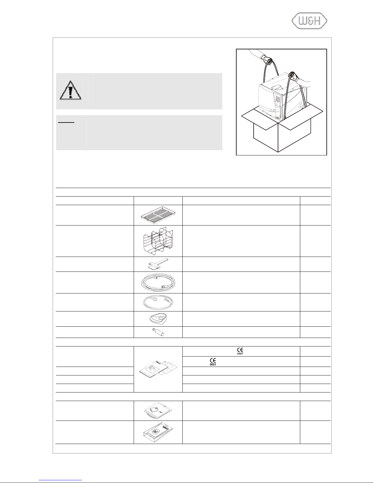
2. UNPACKING ........................................................................................................................................................ 3
2.1 UNPACKING THE STERILIZER................................................................................................................ 3
2.2 STANDARD ACCESSORIES .................................................................................................................... 3
3. UNIT DESCRIPTION ............................................................................................................................................ 4
3.1 FRONT VIEW............................................................................................................................................ 4
3.2 SERVICE DOOR ....................................................................................................................................... 4
3.3 REAR VIEW............................................................................................................................................... 5
3.4 DESCRIPTION OF THE INTERNAL WATER TANKS............................................................................... 6
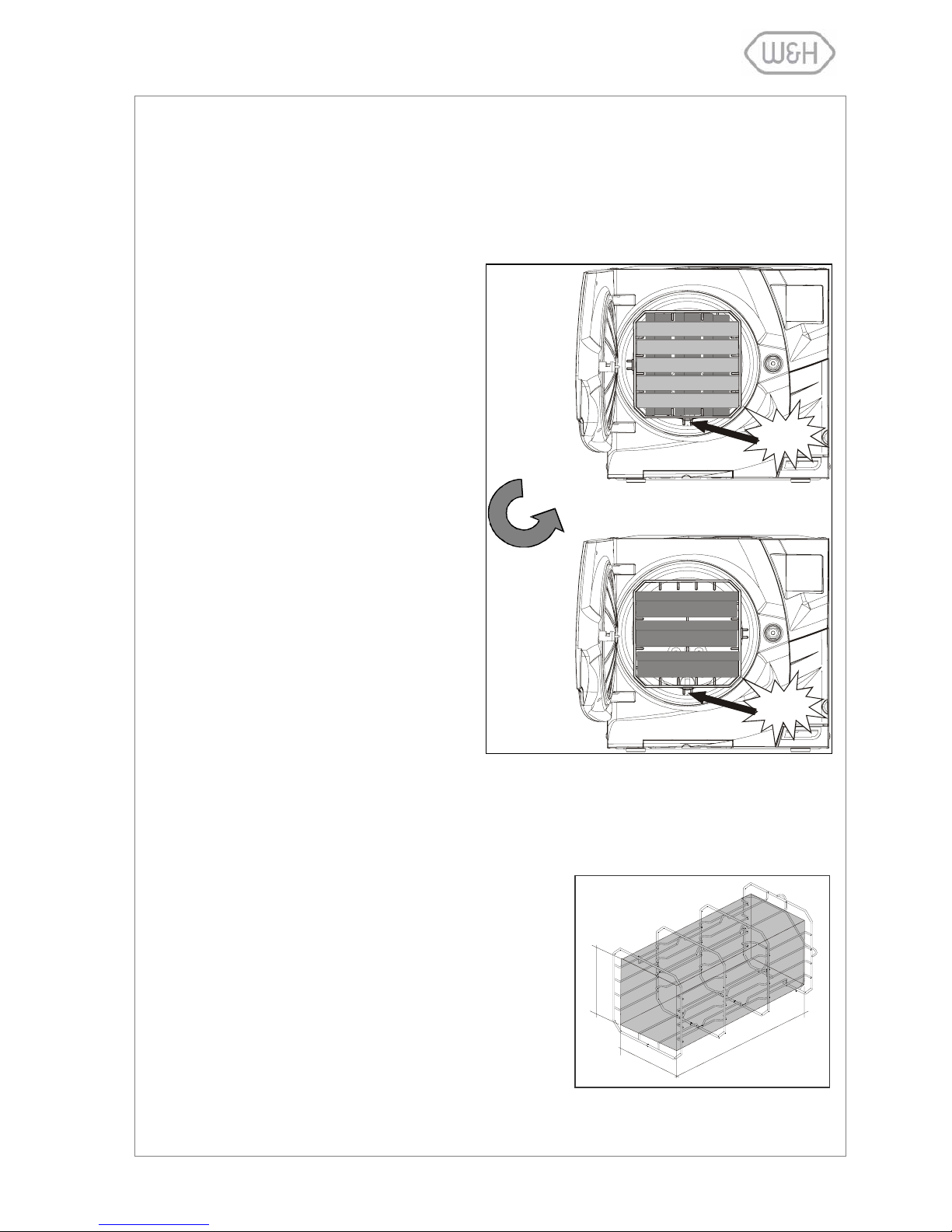
3.5 CHAMBER RACK...................................................................................................................................... 7
3.6 USABLE SPACE IN THE CHAMBER........................................................................................................ 7
4. INSTALLATION.................................................................................................................................................... 8
4.1 SETUP....................................................................................................................................................... 8
4.1.1 Securing the sterilizer with a safety bracket................................................................................. 8
4.2 ELECTRICAL POWER SUPPLY............................................................................................................... 9
4.3 PRINTER (optional)................................................................................................................................... 9
4.4 LABEL PRINTER (optional)..................................................................................................................... 10
4.5 DEMINERALIZER (optional).................................................................................................................... 11
4.5.1 Connecting an external water supply system (demineralizer).................................................... 11
4.6 CONTINUOUS DRAINING (optional) ...................................................................................................... 11
4.6.1 Connecting the drain tube.......................................................................................................... 11
5. GETTING STARTED .......................................................................................................................................... 12
5.1 THE USER INTERFACE ......................................................................................................................... 12
5.2 INITIAL WARNINGS AND SLEEP MODE............................................................................................... 13
5.3 DATE-CLOCK SETTING......................................................................................................................... 13
5.4 FILLING OF THE CLEAN WATER TANK................................................................................................ 14
5.4.1 Manual filling.............................................................................................................................. 14
5.4.2 Automated water supply (optional) ............................................................................................ 14
5.5 DRAINING OF THE USED WATER TANK.............................................................................................. 15
5.5.1 Manual draining......................................................................................................................... 15
5.5.2 Continuous draining................................................................................................................... 15
5.6 MEMORY CARD (optional for 300 Series) .............................................................................................. 15
5.6.1 Inserting / removing the memory card ....................................................................................... 15
6. PROGRAMMING ................................................................................................................................................ 16
6.1 SETUP MENU......................................................................................................................................... 16
6.1.1 Language................................................................................................................................... 17
6.1.2 Sleep mode................................................................................................................................ 17
6.1.3 Printer........................................................................................................................................ 17
6.1.4 Label printer (available with LisaSafe option) ............................................................................ 18
6.1.5 Automatic printing (available with LisaSafe option).................................................................... 18
6.1.6 Manual printing (available with LisaSafe option)........................................................................ 19
6.1.7 Storage time/weeks (available with LisaSafe option)................................................................. 19
6.1.8 User name................................................................................................................................. 20
6.1.9 Date-Clock setting ..................................................................................................................... 20
6.1.10 Date format................................................................................................................................ 21
6.1.11 Clock format............................................................................................................................... 21
6.1.12 Display contrast......................................................................................................................... 21
6.1.13 Display backlight........................................................................................................................ 22
6.1.14 Acoustic tones ........................................................................................................................... 22
6.2 DELAYED CYCLE START ...................................................................................................................... 23

b
6.3 CYCLE HISTORY.................................................................................................................................... 24
6.4 MAINTENANCE....................................................................................................................................... 26
6.5 SERVICE................................................................................................................................................. 26
6.6 TEST CYCLES........................................................................................................................................ 27
6.7 UTILITY................................................................................................................................................... 27
6.7.1 System info................................................................................................................................ 28
6.7.2 Formatting the memory card (optional for 300 Series)............................................................... 28
7. RUNNING A STERILIZATION CYCLE .............................................................................................................. 29
7.1 THE AVAILABLE STERILIZATION CYCLE PROGRAMS....................................................................... 29
7.1.1 Starting a sterilization cycle....................................................................................................... 31
7.1.2 ECO-B option ............................................................................................................................ 31
7.1.3 Cycle in-progress....................................................................................................................... 32
7.1.4 End of cycle............................................................................................................................... 33
7.2 MANUAL STOP....................................................................................................................................... 34
7.3 REAL-TIME CYCLE DATA INFORMATION............................................................................................ 35
7.4 CYCLE DATA SUMMARY....................................................................................................................... 36
8. DISPLAY MESSAGES ....................................................................................................................................... 37
9. ALARMS ........................................................................................................................................................... 39
10. ALARM CODE TABLE....................................................................................................................................... 40
11. MAINTENANCE ................................................................................................................................................. 42
11.1 MAINTENANCE PROGRAM................................................................................................................... 42
11.2 CLEANING THE DOOR SEAL ................................................................................................................ 43
11.3 CLEANING THE CHAMBER AND CHAMBER COMPONENTS ............................................................. 43
11.4 CLEANING THE CHAMBER FILTER...................................................................................................... 43
11.5 CLEANING THE EXTERNAL STERILIZER SURFACES ........................................................................ 44
11.6 REPLACING THE BACTERIOLOGICAL FILTER.................................................................................... 44
11.7 REPLACING THE DUST FILTER............................................................................................................ 44
11.8 CLEANING THE WATER TANKS ........................................................................................................... 45
11.9 REPLACING THE DOOR SEAL.............................................................................................................. 46
11.10 SERVICE CONDUCTED BY AN AUTHORIZED SERVICE TECHNICIAN.............................................. 47
12. USE OF THE MEMORY CARD (optional for 300 series)................................................................................. 48
12.1 TECHNICAL CHARACTERISTICS OF THE MEMORY CARD ............................................................... 48
12.2 READING OF MEMORY CARD DATA WITH A PC/MAC....................................................................... 48
12.3 MINIMUM HARDWARE REQUIREMENTS FOR A PC/MAC.................................................................. 48
12.4 CONNECTING THE EXTERNAL USB CARD READER TO YOUR PC/MAC......................................... 49
12.5 SAVED FILE............................................................................................................................................ 49
12.6 CONTROL CODE.................................................................................................................................... 49
12.7 FILE NAMES ........................................................................................................................................... 49
12.8 DIRECTORY NAME................................................................................................................................ 49
12.9 MEMORY CARD MANAGEMENT (optional for 300 Series).................................................................... 50
12.10 SAVING A FILE....................................................................................................................................... 51
13. TROUBLESHOOTING ....................................................................................................................................... 52
14. RECYCLING / DISPOSAL INSTRUCTIONS...................................................................................................... 53
Appendix 1 TECHNICAL CHARACTERISTICS ................................................................................................... 54
Appendix 2 STERILIZATION LOAD PREPARATION.......................................................................................... 55
Appendix 3 MAINTENANCE OF DENTAL HANDPIECEs ................................................................................... 56
Appendix 4 BOWIE & DICK TEST ....................................................................................................................... 57
Appendix 5 HELIX TEST ...................................................................................................................................... 58
Appendix 6 VACUUM TEST ................................................................................................................................. 59
Appendix 7 WATER QUALITY ............................................................................................................................. 60
Appendix 8 EXAMPLE OF A CYCLE DATA REPORT ........................................................................................ 61
Appendix 9 ACCESSORIES ................................................................................................................................. 62
Appendix 10 HELIX TEST DOCUMENTATION FORM .......................................................................................... 64

1
1. INTRODUCTION
1.1 SCOPE
The purpose of this user manual is to provide you with information about LISA 500/300 Series Steri-
lizers to ensure:
•a proper installation and set-up.
•optimal use.
•a safe and reliable operation.
•regular and correct maintenance and servicing requirements.
NOTE: All drawings, images and texts contained in this manual are the property of the manufacturer.
All rights reserved. Even partial duplication of drawings, images or text is prohibited.
The information contained in this document is subject to change without notice.
1.2 APPLICABLE EUROPEAN DIRECTIVES/NORMS
LISA 500/300 Series Sterilizers conform to the following European Directives:
•Medical Device Directive 93/42/CEE for devices class IIa, in accordance with article 15 - Ap-
pendix IX of the above directive.
•Directive 97/23/CEE (Pressure Equipment Directive – PED) for every sterilization
chamber designed and manufactured in conformity to the Appendix 1 and to the pro-
cedure described in the form D1 annex III.
•Directive 2002/96/CEE (RAEE) for disposal of parts coming from electrical or elec-
tronic parts.
•The sterilizer has been developed, produced and tested in accordance with the new
European Norm relative to small water steam sterilizers EN13060, and with the ap-
plicable safety norms (see Appendix 1).
In the enclosed documents, you will find the Declaration of Conformity and a Warranty Card specific to
your sterilizer.
1.3 INTENDED USE
LISA 500/300 Series Sterilizers are fully automated bench top small steam sterilizers that generate steam
using electrical heaters.
LISA 500/300 Series Sterilizers are used for medical purposes, e.g. in general medical practices, dental
offices, facilities for personal hygiene and beauty care and veterinary practices. They are also used for ma-
terials and equipment, which are likely to be exposed to blood or body fluids, e.g. instruments used by
beauty therapists, tattooists, body piercers and hairdressers.
The types of loads that can be sterilized with Lisa sterilizers are described in the Table 1 of the reference
technical norm EN 13060. These loads include solid, porous, hollow loads type A and hollow loads type B,
unwrapped, single wrapped and double wrapped.
Lisa sterilizers cannot be used to sterilize liquids or pharmaceutical products.

2
1.4 SYMBOLS DISPLAYED ON THE STERILIZER
ATTENTION
Where this symbol is displayed on the sterilizer, the user must refer to this document.
When shown in the user manual this symbol means ATTENTION IMPORTANT NOTES.
To disregard the instructions given in this manual, incorrect use, poor maintenance or
servicing by unauthorized personnel, clears the manufacturer of any responsibility for
warranty and any other claims.
HOT SURFACES
This symbol is displayed at the front of the sterilizer beneath the chamber door. It re-
minds the user to take special care to avoid burns when dealing with the sterilization
load, the sterilization chamber, the chamber door and the area around the chamber
door.
The material the sterilizer is composed of must be disposed according to the directive
2002/96/CEE.
1.5 GENERAL AND SAFETY RECOMMENDATIONS
oThe user is responsible for the proper installation, the correct use and maintenance of the steri-
lizer in accordance with the instructions listed in this manual. For further information call your
local service provider.
oThe sterilizer has not been designed for the sterilization of liquids.
oThe sterilizer must not be used in the presence of gas or explosive vapors.
oThe chamber is automatically heating to 120°C as soon as the sterilizer is switched on.
oThe trays and the sterilization load will be hot at the end of each cycle. Use tray or cassette
holders to empty the sterilization chamber.
oDo not exceed the maximum load weight limits as specified in this manual (see § 7.1)
oDo not remove the nameplate or any label from the sterilizer.
oTo avoid any electrical short circuit, do not pour water or any other liquid over the sterilizer.
oSwitch off the sterilizer and unplug the mains cable before inspecting, carrying out maintenance
or servicing the sterilizer.
oRepairs, maintenance or service must be carried out by authorized W&H service technicians
using original spare parts only.
oIn case of transport:
-Drain both water tanks completely (§ 5.5).
-Allow the sterilization chamber to cool down.
-Use original or appropriate packaging.
Not observing the instructions as specified in this manual can lead to unsafe operation
for the user.

3
2. UNPACKING
2.1 UNPACKING THE STERILIZER
The sterilizer must be removed from the box and
transported by two people.
Total weight: 40 kg (Lisa 317/517)
Total weight: 50 kg (Lisa 322/522)
NOTE: Check the external condition of the box and the
sterilizer. In case of any damages, immediately con-
tact your dealer or shipping agency and the courier
who has carried out the transport.
2.2 STANDARD ACCESSORIES
Following accessories are supplied together with the sterilizer:
ACCESSORIES PLACED INSIDE THE STERILIZATION CHAMBER
Accessory Item Description Quantity
Tray Perforated anodized aluminum tray. 5
Reversible rack
Stainless steel rack to accommodate 5 trays or 3
cassettes.
Optional models available (see Appendix 9). For
more information contact your dealer.
1
Tray holder Tray holder for removing trays from the steriliza-
tion chamber. 1
Drain tube Transparent drain tube with quick connector. 1
Mains cable Length = 2 meters 1
Funnel Funnel to fill the clean water tank. 1
Wall spacer Spacer to keep distance between wall and steril. 2
DOCUMENTS PLACED INSIDE THE PACKAGE
Sterilization chamber: 1
Declaration of conformity CE Sterilizer: 1
User manual Current user manual 1
Warranty Warranty card 1
Works Test Report.
Norm EN 13060: small steam sterilizers. 1
ACCESSORIES PLACED INSIDE THE PACKAGE (500 Series only)
Memory card USB reader External memory card reader 1
Memory card Reads and saves cycle data 1

4
3. UNIT DESCRIPTION
3.1 FRONT VIEW
3.2 SERVICE DOOR
Sliding cover for
manual filling of
the clean water
tank
Service door
Chamber
door
Door seal
Sterilization
chamber
Dust filter
Touch- screen
Door pin
Water tank cover
Bacteriological filter
Main switch
Serial port
(service technicians only)
Slot for memory card
(optional for Series 300)
Quick connector for
manual draining of
clean water tank
Quick connector for
manual draining of used
water tank
Connection to unlock the
chamber door (service
technicians only)

5
3.3 REAR VIEW
Circuit breaker
(manual reset)
Mains plug socket
Condenser vent
Mains cable guide
Parallel port
(printer)
Data connection for
external water supply
system
Pressure safety valve
cover
Serial port (printer)
Air filter Spare fitting
Fitting for the connec-
tion of an external water
supply system
Fitting for continuous
draining of used water
tank

6
3.4 DESCRIPTION OF THE INTERNAL WATER TANKS
The sterilizer is equipped with two independent water tanks, one for clean water and one for used water
(capacity of 3.5 liters each).
The tank on the right side is called "clean water tank" and has to be filled with distilled or demineralized
water required for the sterilization process. It is fitted with a minimum (0.6l) and a maximum (3.5l) water
level sensor. The tank can be filled manually through the tank hole on the top of the sterilizer or automati-
cally with an external water supply system (LisaDem 32 or LisaOsmo) connected to point D2 at the back of
the sterilizer (see § 4.5).
Use the quick connector behind the service door (left/blue) to drain the clean water tank for cleaning pur-
poses (see chapter on maintenance).
The tank on the left side is called "used water tank"and contains the used water collected at the end of
each sterilization cycle. It is fitted with a maximum water level sensor (3.5l).
Use the quick connector behind the service door (right/gray) to drain the used water tank (see chapter on
maintenance).
The used water tank can also be drained automatically by connecting a drain tube to the D4 fitting located
at the back of the unit (see § 3.3 and § 4.6).
NOTE: The water consumption per sterilization cycle varies depending on the type and weight of the
sterilization load. The capacity of the clean water tank is sufficient to run 8 - 12 sterilization cy-
cles.
Used water tank
Water level sensors
Quick connector for
manual draining of
clean water tank
Quick connector for
manual draining of used
water tank
Water inlet for manual filling of
clean water tank
Fittings for automatic fill-
ing/draining of tanks
Clean water tank

7
3.5 CHAMBER RACK
Insert the rack into the sterilization chamber, align it at the center/bottom of the chamber and push it gently
into position until it clicks.
The chamber rack is reversible and can be used for:
5 trays horizontally or 3 cassettes vertically
or
3 trays or 3 cassettes horizontally.
3.6 USABLE SPACE IN THE CHAMBER
The chamber usable space is the maximum volume of the chamber for accommodating a sterilization load.
This volume is equivalent to a pipe with the following dimensions:
Lisa 317/517
195 x 195 x 297mm (WxHxD); equal to the volume of
11.5 liters
Lisa 322/522
195 x 195 x 390mm (WxHxD); equal to the volume of 15
liters
The capacity/volume is identical for all sterilization cycles and
types of load.
H
W
D
90°
Click!
Click!

8
4. INSTALLATION
4.1 SETUP
The sterilizer has been calibrated and intensively tested in the factory prior to shipping. It does not require
any calibration during installation.
Observe the following environmental conditions:
Working temperature range: from +5°C to +40°C / relative humidity: 0 … 90%
Storage temperature range: from -20°C to +60°C / relative humidity: 0 … 90% (empty tanks)
Install the sterilizer as outlined below:
•Place the sterilizer on a flat and level surface.
•The maximum weight of the sterilizer with a full clean wa-
ter tank and the chamber fully loaded is:
48.5 kg – 57.2 N/m² - 120 N/sq ft. (Lisa 317/517)
58.5 kg – 71 N/m² - 145 N/sq ft. (Lisa 322/522)
•Leave a gap of 50mm in the back and 10mm on each
side of the sterilizer to ensure adequate ventilation.
Mount the supplied wall spacers at the back of the
sterilizer (see image to the right).
•Do not place the sterilizer near a sink or in a location
where it is likely to be splashed with water - danger of
electric short circuit!
•Install the sterilizer in a well-ventilated room.
•Keep the sterilizer away from all sources of heat.
4.1.1 Securing the sterilizer with a safety bracket
If the bench on which the sterilizer is installed is small, there is a
risk of the sterilizer tilting when the chamber door is opened and
leaned upon.
Use the safety bracket (optional; see Appendix 9) to avoid that.
-Move the two front feet in the rear position.
-Drill two holes on the installation surface and fix the bracket
with the supplied screws.
40
113
Refer to safety bracket installation procedures for further details.
-Position the sterilizer on the bench with one of the rear feet
inserted in the safety bracket.
Wall
Minimum distance
2 holes Ø3x20
Screws Ø4,8x22

9
4.2 ELECTRICAL POWER SUPPLY
The electrical installation used for the sterilizer must comply with the current standards in the country of
use.
-The electrical supply must be single-phase 200-240 VAC ±10%, 50/60 Hz, 10 A on a dedicated circuit.
-Installation category / mains overload category = II
-Maximum power consumption of the sterilizer is 2,000-2,400 W (10 A)
-A grounded connection is essential.
The electrical supply to which the sterilizer is connected must
be composed of:
-A grounded plug.
-A 10 A differential circuit breaker with a sensitivity of 30
mA. The circuit breaker must be a certified type according
to applicable norms.
Plug in the mains cable at the back of the sterilizer.
-Check that the voltage specified on the nameplate located on the backside of the
sterilizer corresponds to the supplied mains voltage.
-The overall electrical safety of the sterilizer is guaranteed only if the mains volt-
age supply is properly grounded according to all applicable norms.
-If unclear, have the electrical installation checked by a qualified electrician.
-Do not plug other equipment into the same socket/circuit.
-Do not bend or twist the mains cable.
-Use only the original cable as supplied with the sterilizer.
-Do not use cable extensions.
4.3 PRINTER (optional)
We recommend the use of LisaPrint (conforms to the IEC 61010-1 norm) as it has
been tested for compatibility with the sterilizer and its software.
The use of printers other than the ones listed in the relevant printer setup menu (see
6.1.3) clears the manufacturer of any responsibility for warranty or any other claims.
-Connect the printer cable to the 25-pin parallel port
socket at the back of the sterilizer. Cable length should
not exceed 2 meters.
-Connect the printer mains cable.
-Switch ON the printer.
-Select the printer type (§6.1.3). LisaPrint is the default
setting.
All necessary data to document sterilization cycles is printed
(for details see Appendix 8).
NOTE: Lisa 517/522 sterilizers offer the option to digitally record cycle data on removable
memory cards. Cycle data can be saved, read and printed on a regular PC/MAC (see §
12).

10
LISA 317 06-0123 00.12.00.00.00
ROSSI MARIO
Date: 25-10-07 10:48:00
Cycle: B-UNIVERSAL 134
Number: 00001
Expiry date:
22-11-2007
C00EABD00001
4.4 LABEL PRINTER (optional)
We recommend using the printer TLP 2824 (conforms with norm CEI 61010-1) which
has been tested and is compatible with the Lisa sterilizer and its software.
The use of other printers removes all responsibility from the manufacturer with re-
gards to the correct functioning of the system, the guarantee and all other claims.
- Please refer to the label printer manual or
quick-start guide for instructions on how to
mount the roll of labels and ink ribbon.
- Connect the hardware key to the serial port
at the back of the printer.
- Connect the serial cable between the hard-
ware key and the serial port at the back of
the sterilizer.
- Plug in the printer’s power cable at the
mains supply.
- Switch on the printer by pressing the main
interrupter on the right-hand side.
- Select the type of printing (automatic or
manual) and other options in the sterilizer
sub-menus.
- After installation, the printer automatically
carries out calibration to obtain the format of
the labels used. For this to take place, the
label printer must be connected, switched
ON with the label roll and ribbon inserted.
Access the setup menu, select the label
printer option, and select the printer model
to be used (see 6.1.4).
Carry out the selection procedure to cali-
brate the printer, even if the printer is al-
ready set to the correct model.
During calibration, the printer may use up a
few labels, but this is perfectly normal and
these labels can be disposed of.
If the calibration process has not been car-
ried out correctly or it has been carried out
correctly but the label format does not cor-
respond to that selected for the application,
the printer may present anomalies during
printing such as blocking, leaving blank la-
bels or printing only partial information etc.

11
4.5 DEMINERALIZER (optional)
W&H Sterilization offers external water supply systems for automated supply of demineralized water to the
sterilizer(s) (LisaDem32 or LisaOsmo). Once installed, the clean water tank no longer needs to be filled
manually but will be filled automatically with demineralized water. The LisaDem32/LisaOsmo utilize resin
cartridges to remove minerals from city water to assure a constant good water quality for the sterilization
process.
4.5.1 Connecting an external water supply system (demineralizer)
To install a LisaDem32/LisaOsmo water supply system,
an interface cable and the fittings D2 and D4 located at
the back of the sterilizer are used.
For more information, refer to the LisaDem32/LisaOsmo
user manuals.
4.6 CONTINUOUS DRAINING (optional)
4.6.1 Connecting the drain tube
The sterilizer can be connected to a drain (or simply to a
sink) for continuous draining of the used water.
-Unscrew the plug from the D4 fitting at the back of
the sterilizer.
-Install the 1/8” barber fitting and the drain tube from
the kit and route the tube to a drain or sink (kit or-
dering number: G0053060). If unclear, have the in-
stallation checked by a qualified plumber.
The drain tube must not be longer than 5
meters.
The draining point must be at least 20cm
below the surface on which the sterilizer
is placed.
For further information, refer to the LisaDem32/LisaOsmo
user manuals.
Interface cable
D2 = filling
D4 = draining
Drain tube
Drain

12
5. GETTING STARTED
5.1 THE USER INTERFACE
To power the sterilizer press the main switch located behind the service
door (see image to the right).
When the sterilizer is switched ON, the chamber auto-
matically heats to 120°C.
This process (pre-heating) takes approximately 10 min-
utes.
If a sterilization cycle is initiated during the pre-heating
phase, it will start automatically once the pre-heating
temperature is achieved.
Once the sterilizer is switched on, the following screen appears:
To run a sterilization cycle, place the load in the sterilization chamber and close the chamber door. Select
a cycle by pressing the “Cycle selection” icon and confirm the selection by pressing the “Selection confir-
mation” icon.
A screen will inform you about the maximum load weight limits for the cycle you selected. Initiate the cycle
by pressing the “Start cycle” icon.
Menu option
Sleep mode
A
vailable cycles
Current date Current time
Cycle selection
Cycle counter
Selection
confirmation
Start cycle

13
5.2 INITIAL WARNINGS AND SLEEP MODE
This message will appear if the sterilizer is switched on and the clean water tank is empty. Fill the clean
water tank with distilled or demineralized water (see § 5.4).
NOTE: If this message is displayed it is not possible to initiate a sterilization cycle. The mes-
sage disappears automatically once the clean water tank is filled.
If the sterilizer is not used for a certain programmable time period, it will automatically switch to “Sleep
mode” to conserve energy (programmable time-out; default 1 hour; see § 6.1.2). Press the “Sleep mode”
icon to get back to the main menu.
5.3 DATE-CLOCK SETTING
To properly save or print cycle data on a memory card or on a printout, the internal sterilizer time and date
has to be set since these parameters are included in the sterilization cycle data report. Please refer to §
6.1.9 for details on how to properly set the sterilizer date and time.
Sleep mode

14
5.4 FILLING OF THE CLEAN WATER TANK
5.4.1 Manual filling
Use only high quality distilled or demineralized water (see Appendix 7).
•Slide the tank cover to the right to access the
clean water tank inlet.
•Remove the cap (1) from the tank inlet.
•Insert the funnel and fill the clean water tank
with app. 3.5 liters of distilled or demineralized
water.
•Once the clean water tank is almost full, an
audible tone will sound. You can add some
more water but make sure that water does not
overflow.
•Place the cap (1) to close the tank.
•Slide the tank cover back into its original posi-
tion.
•Drain the used water tank.
1
2
The water level in the clean water tank decreases during every sterilization cycle, while the used water
tank level is rising. The sterilizer is equipped with an internal water conductivity sensor that constantly
monitors the water quality. Should the water quality go beyond a maximum threshold (>15µS/cm con-
ductivity), a warning message is displayed on the screen.
Every time you fill the clean water tank drain the used water tank (see § 5.5).
5.4.2 Automated water supply (optional)
If an automated water supply system is connected to the sterilizer
(see § 4.5), the clean water tank gets automatically filled once the
water level drops below the minimum level.
An internal water conductivity sensor constantly monitors the water
quality. Should the water quality go beyond a maximum threshold
(>15µS/cm conductivity as defined by the European Norm EN
13060), a warning message is displayed on the screen (see screen-
shot to the right).
Water of low quality can impair the sterilization process and seriously damage the in-
ternal components of the sterilizer. Damages caused by poor water quality will not be
covered by the manufacturer’s warranty. Once this message is displayed, check the
water source (refer to the water supply system user manual; replace resin cartridges
etc.). In case distilled or demineralized water is purchased from the market, switch to a
brand of better quality.

15
5.5 DRAINING OF THE USED WATER TANK
When the waste water in the used water tank reaches the maximum
level, the following message is displayed:
The message will disappear once the used water tank got drained.
Keep draining the tank until it is completely empty.
5.5.1 Manual draining
•Open the service door at the front of the sterilizer.
•Insert the drain tube into the quick connector for the
used water (gray connector / right).
•Let the used water tank drain until it is completely
empty.
•Press the push-button on top of the quick connector to
dislodge the drain tube.
NEVER RE-USE THE USED WATER!
5.5.2 Continuous draining
If the permanent drain tube for automated draining of the used water is mounted, the used water tank gets
drained automatically. For more information see § 4.6.
If the sterilizer is not used for more than 3 days, both water tanks must be com-
pletely drained in order to avoid algae growth or any other deposits.
5.6 MEMORY CARD (optional for 300 Series)
5.6.1 Inserting / removing the memory card
All models of the Lisa 500 Series (optional for 300 Series) are
equipped with a digital cycle data recording system. Cycle data is
written and saved on removable/rewritable memory cards.
-Insert the memory card into the dedicated slot behind the service
door until it clicks into its final position. Ensure that the flat corner
of the card points to the top/right (see image to the right).
-Periodically remove the memory card to download cycle data to
a computer.
-To remove the memory card, slighty push it in and pull it out
gently.
For further instructions on the use of the memory card, see § 12.

16
6. PROGRAMMING
LISA 500/300 Series Sterilizers are equipped with a software that allows the user to program a number of
different features. The following section shows step by step how each of these features can be pro-
grammed.
Press the menu command icon to view the list
of available options.
The available menu options are shown
below:
6.1 SETUP MENU
Complete Setup menu
§ 6.1.1 – Language
§ 6.1.2 – Sleep mode
§ 6.1.3 – Printer
§ 6.1.4 – Label printer *
§ 6.1.5 – Automatic printing *
§ 6.1.6 – Manual printing *
§ 6.1.7 – Storage time *
§ 6.1.8 – User name
§ 6.1.9 – Date-Clock setting
§ 6.1.10 – Date format
§ 6.1.11 – Clock format
§ 6.1.12 – Display contrast
§ 6.1.13 – Display backlight
§ 6.1.14 – Acoustic tones
* The sub-menus regarding label printing are
only available with the option LisaSafe with
the hardware key and printer plugged in cor-
rectly.
Menu
A
bort and return
to previous
screen
Scroll up
Scroll-down
Current
selection
Selection
confirmation

17
6.1.1 Language
Use this menu to select the user interface language.
6.1.2 Sleep mode
In “Sleep mode” the sterilizer reduces the power consumption to a minimum. The sterilizer will switch to
sleep mode whenever it is idling without being used. Use this menu to program the time before the steri-
lizer switches to sleep mode.
•The time range is from 0 (never in sleep mode) to 8 hours. The factory setting is 1 hour.
•The time can be set in fixed increments of 10 minutes.
6.1.3 Printer
Use this menu if you want to connect a printer for cycle data recording. Select the printer by using the
scroll icons, press “Confirm” to save the configuration. For more information on connecting a printer to your
sterilizer, see § 4.3.
Abort and return to
previous screen Scroll up
Cursor
Scroll down
Selection
confirmation
Abort and return to
previous screen Increase time
Decrease time
Selection
confirmation
Scroll up
Current selection
Scroll down
Confirm and return to
previous menu
Abort and return to
previous screen
This manual suits for next models
1
Table of contents
Popular Steriliser manuals by other brands

Tommee Tippee
Tommee Tippee 1069 Instructions for use

Lena Lighting
Lena Lighting UV-C Sterilon Air Z1 user manual

Tommee Tippee
Tommee Tippee ultrauv Instructions for use

Market Forge Industries
Market Forge Industries STM-ED owner's manual

MILOO-ELECTRONICS
MILOO-ELECTRONICS STERYLIS VS-100/450 manual

Philips
Philips Avent SCF288 Important product information