Listen LR-600 User manual

User’s Manual
LR-600 Wireless Speaker / Receiver
Listen Technologies Corporation
8535 South 700 West, Suite A
Sandy, Utah 84070-2515 USA
Telephone: +1.801.233.8992
Toll Free (North America): 1.800.330.0891
Fax: +1.801.233.8995
E-mail: info@ListenTech.com
Don’t miss a single sound. Listen.

Welcome to Listen!
Dear Valued Customer,
Thank you for choosing Listen! All of us at Listen are dedicated to providing you
the highest quality products and prompt, efficient customer care. Our products are
manufactured in an ISO-9000 factory that has been independently certified to the
highest quality standards. We stand ready to answer any questions you might have
during installation or in the operation of our products. Should there be any prob-
lems with your Listen products, we are ready to help you in any way we can.
Should you have any comments on how we might improve our products or our
service, we’re here to listen. Here’s how to reach us:
Telephone: +1.801.233.8992
Fax: 1.801.233.8995
Toll Free (North America): 1.800.330.0891
E-Mail: support@ListenTech.com
Web: www.ListenTech.com
Thank you... and enjoy your listening experience!
Best regards,
The Listen Team
iListen™ and the Listen Logo are registered trademarks of Listen Technologies Corporation.
LR-600_2004_08_02 © 2004 Listen Technologies Corporation. All Rights Reserved.
· LR-600 Wireless Speaker / Receiver
(72MHz or 216MHz)
· Adjustable/removable handle/mounting bracket with
leatherette cover
· LA-201 Power Supply
· (2) .18 in (4.5mm) x 1.38 in (35mm) screws with hol-
low wall anchors
· (1) 16mm nut for mounting the LR-600 on a micro-
phone stand
· Warranty Card
· User Manual
LT-800 Package Contents
72 MHz: LR-600-072
216 MHz: LR-600-216
Listen Part Number
See page 26-27
Optional Accessories

Table of Contents
Architectural Specifications . . . . . . . . . . . . . . . . . . . . . . . . . . . . . . . . . . . . . . . . . . .2
Specifications . . . . . . . . . . . . . . . . . . . . . . . . . . . . . . . . . . . . . . . . . . . . . . . . . . . . . . .2
Block Diagram . . . . . . . . . . . . . . . . . . . . . . . . . . . . . . . . . . . . . . . . . . . . . . . . . . . . . .3
Quick Reference . . . . . . . . . . . . . . . . . . . . . . . . . . . . . . . . . . . . . . . . . . . . . . . . . . . .4
Powering Instructions . . . . . . . . . . . . . . . . . . . . . . . . . . . . . . . . . . . . . . . . . . . . . . . .5
Internal Batteries . . . . . . . . . . . . . . . . . . . . . . . . . . . . . . . . . . . . . . . . . . . . . . . . . . . .6
Antenna Options . . . . . . . . . . . . . . . . . . . . . . . . . . . . . . . . . . . . . . . . . . . . . . . . . . .8
Setup & Programming . . . . . . . . . . . . . . . . . . . . . . . . . . . . . . . . . . . . . . . . . . . . . . . .9
Squelch Adjustment . . . . . . . . . . . . . . . . . . . . . . . . . . . . . . . . . . . . . . . . . . . . . . . .11
External Speaker . . . . . . . . . . . . . . . . . . . . . . . . . . . . . . . . . . . . . . . . . . . . . . . . . . .12
Auxiliary Input and Output . . . . . . . . . . . . . . . . . . . . . . . . . . . . . . . . . . . . . . . . . .12
Operation . . . . . . . . . . . . . . . . . . . . . . . . . . . . . . . . . . . . . . . . . . . . . . . . . . . . . . . . .13
Battery Options . . . . . . . . . . . . . . . . . . . . . . . . . . . . . . . . . . . . . . . . . . . . . . . . . . . .14
Mounting & Carrying Options . . . . . . . . . . . . . . . . . . . . . . . . . . . . . . . . . . . . . . . .15
RF Reception Maximization Strategies . . . . . . . . . . . . . . . . . . . . . . . . . . . . . . . . .17
Listen SQ™ . . . . . . . . . . . . . . . . . . . . . . . . . . . . . . . . . . . . . . . . . . . . . . . . . . . . . . .18
Coaxial Cable . . . . . . . . . . . . . . . . . . . . . . . . . . . . . . . . . . . . . . . . . . . . . . . . . . . . .18
Channel Selection . . . . . . . . . . . . . . . . . . . . . . . . . . . . . . . . . . . . . . . . . . . . . . . . . .19
72 MHz Frequency Compatibility Table . . . . . . . . . . . . . . . . . . . . . . . . . . . . . . . . .20
216 MHz Frequency Compatibility Table . . . . . . . . . . . . . . . . . . . . . . . . . . . . . . . .21
Troubleshooting . . . . . . . . . . . . . . . . . . . . . . . . . . . . . . . . . . . . . . . . . . . . . . . . . . . .22
FCC Statement . . . . . . . . . . . . . . . . . . . . . . . . . . . . . . . . . . . . . . . . . . . . . . . . . . . .24
Warranty . . . . . . . . . . . . . . . . . . . . . . . . . . . . . . . . . . . . . . . . . . . . . . . . . . . . . . . . .25
Optional Accessories . . . . . . . . . . . . . . . . . . . . . . . . . . . . . . . . . . . . . . . . . . . . . . . .26
Table of Contents

Specifications
Architectural Specifications
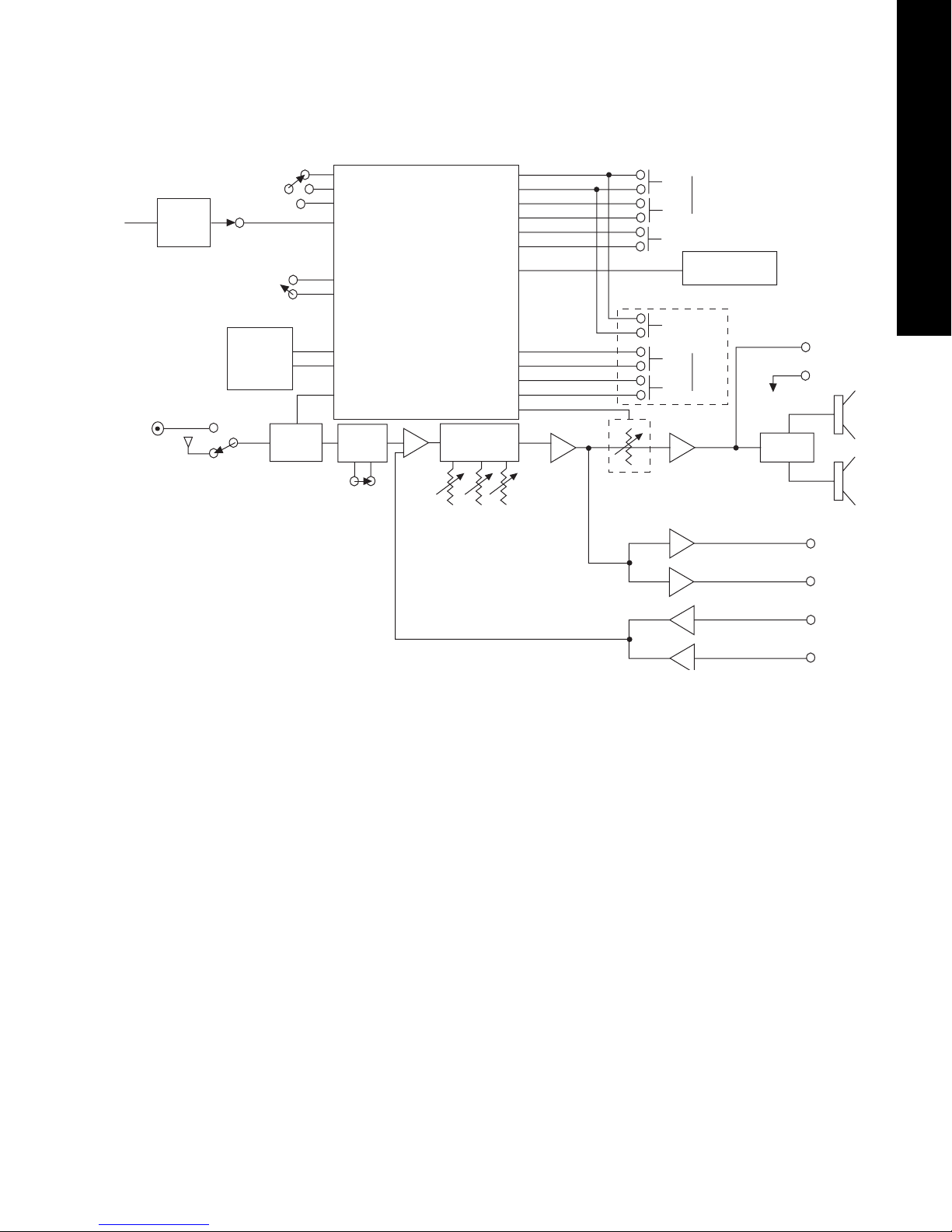
The FM speaker/receiver shall be capable of receiving on 57 wide and narrow band channels. The
speaker/receiver shall be have 10 watts output power and have a frequency response of 50Hz to 15KHz, ±
3dB at 72MHz, or of 50Hz to 10kHz, ± 3dB at 216MHz. The signal to noise ratio shall be 80dB or greater.
The device shall have an adjustable squelch and three-band equalizer. The device will incorporate a backlit
LCD Display that indicates channel and RF signal strength, as well as be used for channel selection
programming. The unit shall be programmable to display only used channels. It shall also incorporate an
electronically lockable volume and channel controls. Controls should be found on the top and rear of the
unit. The device shall incorporate a power supply (120VAC, 60Hz, 43 Watts), with output DC 12V 2500
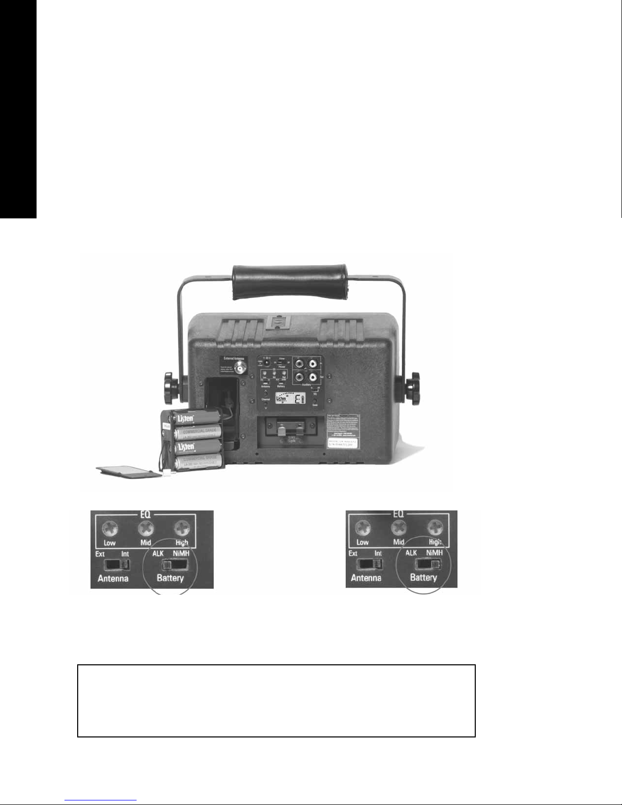
mA tip negative. It will alternately use an internal battery pack using eight AA alkaline or NiMH
Rechargeable batteries and include recharging components for said NiMH batteries. The speaker should
have a minimum SPL of 110dB (±3dB). An included bracket will be able to be used as a handle for carrying,
or be adjustable up to 360 degrees around the unit for mounting. The Listen LR-600 is specified.
Specifications
2
Specifications
Specification LR-600-072 LR-600-216
RF Frequency Range 72.025 - 75.950 MHz 216.025 - 216.975 MHz
Number of Channels 57 (17 wide, 40 narrow) 57 (19 wide, 38 narrow)
Sensitivity
Frequency Accuracy
Antenna
Optional Antennas
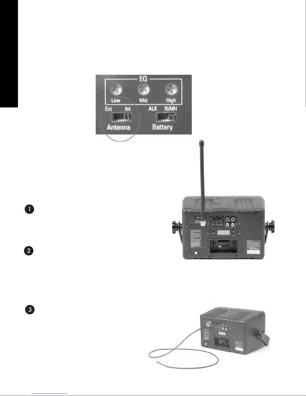
External Antenna Connector
Squelch
Compliance
System Frequency Response 72MHz: 50Hz - 15kHz (± 3dB) 216MHz: 63Hz - 10kHz (± 3dB)
System Signal to Noise Ratio
(A-weighted)
SQ enabled: 80dB;
SQ disabled 60dB at 72 MHz
SQ enabled: 80dB;
SQ disabled 50dB at 216 MHz
System Distortion
Equalizer
Unbalanced Auxiliary Input
Unbalanced Output
Internal/External Speaker Output
Set-up Controls, Back Panel
User Controls, Top Panel
User Controls, Back Panel
Programming
Indicators LCD Display
Power Supply Type
Power Supply Input
Power Supply Output
Power Supply Connector
Compliance
Optional Battery
Optional Battery Charging
Battery Life (Listen batteries)
Dimensions
(with bracket/handle in up position)
Dimensions (without bracket/handle)
Unit Weight
Unit Weight with LA-201 Power Supply
Unit Weight with eight AA batteries
Shipping Weight
Micophone Stand Mounting Nut
Temperature - Operation
Temperature - Storage
Humidity
Environmental
6.8 lbs (3.1kg)
Power
Physical
15VAC, 1A
6.2 lbs (2.8kg)
16mm
UL Listed
10 lbs (2.8kg)
0 to 95% relative humidity, non-condensing
<2% total harmonic distortion (THD) at 80% deviation
Two phono connectors, unbalanced, -10dBu nominal input level adjustable,
+11dBu maximum, impedance 100k Ohms
In-line power supply, Listen part number LA-201
-10° to +40°C (14° to 104° F)
Two phono connectors, unbalanced, 0dBu nominal output level,
+11dBu maximum, impedance 1k Ohms
-20° to +50°C (-4° to 122° F)
Backlit, indicates channel, RF signal strength, lock status, programming
.02 in OD x .01 in ID (5.0mm x 2.5 mm), barrel type
Eight AA batteries, alkaline or NiMH.
9.0 in x 7.0 in x 7.0 in WxDxH (22.9cm x 17.8cm x 17.8cm)
Fully automatic, 14 hours
7.6 lbs (3.5kg)
RF
Audio
Internal/External Antenna, Alkaline/NiMH Batteries, SQ Enabled/Disabled
Controls
** All system specifications are wireless end-to-end
Internal
Three band, continuously adjustable via rear panel trim pots.
.6uV typical, 1 uV maximum for 12dB SINAD
15/10 Watts (peak/RMS) continuous power with 4 Ohm load
BNC
± .005% stability -10° to 40° C (14° to 104° F)
Power/Charging, channel UP/DOWN, SEEK (channel, SEEK and volume are lockable)
11.0 in x 9.0 in x 7.0 in WxDxH (27.9cm x 22.9cm x 17.8cm)
Handle stands off unit 2.0 in (5.1cm)
FCC Part 15, Industry Canada
12+ hours alkaline (LA-361), 10+ hours NiMH rechargeable (LA-362), mid volume,
music programming (volume and audio type will effect battery life)
Programmable in 20 steps
120VAC, 60 Hz, 19 Watts (maximum continuous)
Unit can be programmed so that only desired channels are displayed. Squelch can
be adjusted for sensitivity. Channel and volume can be locked.
Several available. See www.ListenTech.com for details
Volume UP/DOWN, Channel UP (lockable)

Power Supply
CPU Module
(8) AA Batteries
Alkaline or NiMH
115VAC
External
Power Supply
18VAC UL
Listed +12VDC or
8VAC
Power
Off/Charge/On
ALK
NiMH
Battery
Select
BNC External
Internal
Antenna
Receiver
RF Board SQ EQ
SQ On/Off
Phono
Phono
Auxiliary
Input
Auxiliary
Output
Low Mid High
Digital Pot
15/10 Watt
(peak/RMS)
Power Amp
Up Volume
Down
Select
Top of Speaker
Crossover
Network
Mid Range
Tweeter
Speakers
External
Speakers
Terminals
Listen LCD Display
(backlighted)
Seek
Down
Up Channel
Block Diagram
3
LR-600 Block Diagram

Quick Reference
4
EQ
Channel
Select
UP
DOWN
Volume
Quick Reference
LR-600 Rear Panel: Connections and Controls
EXTERNAL ANTENNA
If you need more receiving
range, connect an external
antenna here. Antennas
are available from Listen.
POWER
Connect the (included) power
supply here, or a +12VDC
power source such as a
vehicle power adapter.
EQ
Three-band equalizer
used to adjust sound
quality to meet your
needs.
LR-600 LCD Panel Details
ON / CHARGE / OFF
To operate and charge batteries,
move to ON position. To only
charge batteries, move to CHG
position. See page 7.
AUXILIARY CONNECTORS
To listen to a CD, TV, etc
through the speaker, connect
to AUX IN; to route audio to an
external device such as a
recorder or mixer, connect to
AUX OUT.
SQ MODE
When ON, activates the Listen
SQ mode, improving noise
performance by better than
20dB. Transmitter must also
have SQ enabled to use this
mode.
EXTERNAL SPEAKER
Connect an external
speaker here.
CHANNEL UP / DOWN and
SEEK
Use to select and search
channels, or to program the
unit.
BATTERY COMPARTMENT
Remove access panel to
change batteries. Unit holds
eight optional AA batteries
(NiMH rechargeable or
alkaline).
LCD PANEL
See below
ANTENNA SELECT
If you connect an external
antenna, move this
switch to EXT. If no
external antenna is used,
the switch should be on
INT.
RF Signal Strength
PGM - indicates the unit is in
the program mode that allows
you to lock out channels that
are not used.
LOCK - When the padlock icon is visible, the channel buttons
are locked and you cannot change the channel. When the
padlock is flashing, both the channel and volume buttons
are locked. To lock channels, press and hold SEEK for 5
seconds. Repeat to unlock. To lock channels and volume,
press SEEK and then the UP button. Press SEEK and then
DOWN to unlock.
Indicates channel, or when volume up or down
button is pressed, indicates volume.
L/O - When in the programming mode,
this symbol indicates the channel is
locked out and will not be displayed to
the user.
Channel
Select
UP
DOWN
Volume
LR-600 Top Panel Details
CHANNEL SELECT
Selects the next
programmed
channel.
VOLUME
Adjusts volume up
and down.Volume
setting of 0 to 26
is indicated on
rear panel LCD.

Powering
5
There are three options for powering your LR-600:
· Supplied power supply
· External +12VDC Battery or Power Supply
· Internal Batteries
Power Supply (included with unit)
If you are using the LR-600 with the external power supply, connect the power supply to the LR-600
and plug the power supply into a 115VAC/60 Hz outlet.
External +12VDC Source
If you are using the LR-600 with an external +12VDC battery or power supply, obtain a power
connector with following dimensions:
0.098 in (2.5 mm) inside diameter
0.217 in (5.5 mm) outside diameter
0.374 in (9.5 mm) length
Wire the connector so the tip is positive. Connect to a 12VDC battery or +12VDC output of a
power supply.
LR-600 Powering Instructions

LR-600 Internal Batteries
Internal Batteries
6
Internal Batteries
If you are using the LR-600 with internal batteries, do the following:
· Open the battery compartment by removing the thumbscrew and then removing the cover.
· Slide the battery holder out of the battery compartment.
· Install eight AA alkaline or NiMH batteries with polarity noted on the battery holder.
· Replace the battery holder and secure the battery compartment cover.
IMPORTANT: Slide the battery switch to the alkaline or NiMH battery position depending on the
battery type you are using.
Place the Battery switch in the ALK
position if you are using alkaline
batteries.
Place the Battery switch in the NiMH
position if you are using rechargeable
NiMH batteries.
IMPORTANT: You must place the Battery switch in the appropriate position for the type of
batteries you will be using. If you are using alkaline batteries and the switch is in the NiMH
position, the unit will attempt to charge the batteries when connected to a power supply or
external battery. Attempting to charge alkaline batteries can result in permanent damage
to the unit, and the batteries may explode.

Internal Batteries
7
LR-600 Internal Batteries continued
For NiMH battery operation, you must charge the batteries for 13 hours before use. To charge the
batteries, plug the unit into the power supply or external +12VDC supply and move the power
switch to either CHG or ON. The batteries will charge in either position.
Powering the unit ON
Turn the unit on by sliding the power switch to the ON position. The LCD will activate; if using the
LR-600 on the power supply, the LCD backlight will activate and remain on. If you are using the
unit on batteries, the LCD backlight will operate for 12 seconds after any button is pressed, and then
dim to conserve battery life.
In Charge mode, the battery symbol
will cycle between low, mid and full.

Antenna Options
8
LR-600 Antenna Options
The LR-600 has two antenna options: internal or external. To use the internal antenna, move the
antenna switch to INT. To use the external antenna, move the switch to EXT.
Internal antenna
As shipped, your LR-600 is set up for use with its internal antenna. The
internal antenna will work well for a large number of uses, but it cannot be
positioned for best coverage. When using the LR-600’s internal antenna,
make sure the antenna switch is in the INT position. If your receive signal
is noisy or weak, you may need to use an external antenna.
External antenna
There are three options for the external antenna:
Quarter wave helical antenna
This antenna mounts directly to the back of the LR-600. Order
these part numbers from Listen:
· LA-123 (72 mHz)
· LA-124 (216 mHz)
Remote antenna
See page 17, RF Reception Maximization Strategies. With a remote
antenna, you’ll be able to get the best reception by strategically placing
the antenna.
Antenna options available from Listen:
· LA-122 Universal Antenna Kit (72 and 216 mHz)
· LA-123/LA-124 (72/216 mHz) to be mounted remotely
· LA-107 Ground plane antenna (216 mHz).
Wire antenna
You can build a wire antenna by soldering a wire to the center conductor on
a BNC connector. Recommended lengths for wire antennas:
· 72 mHz: 39 in (1 m)
· 216MHz: 13 in (0.32 m)

Setup & Programming
9
LR-600 Setup and Programming
Channel Selection
Using the channel select buttons (UP and DOWN buttons on the rear panel) or the SEEK button,
select the desired receive channel. For more information, see Channel Selection on page 19.
Locking Channel Selection
If you don’t want the user to have the ability to change the channel, it is highly recommended that
you lock the channel select function. This is accomplished as follows:
· Press and hold the SEEK button for 5 seconds.
· The padlock icon will appear in the display.
· To unlock the channel selection function, press and hold the SEEK button until the
padlock icon goes out.
Locking Both Volume and Channel Selection
Once the channel and desired volume have been set, you can lock both functions as follows:
· Press the SEEK button and then the UP button on the rear panel.
· The PADLOCK icon will flash.
· To unlock both the volume and the channel selection function press the SEEK button and then
the DOWN button on the rear panel.
Setting the SQ
Use Channel UP / DOWN or Seek to
select a receive channel.
A padlock in the display means the channel
is locked and a new channel cannot be
selected. If the padlock icon is flashing, both
the channel and volume settings are locked
(see below).
Press Seek, and then the Channel UP button to lock volume and channel.
Press Seek, then DOWN to unlock.

Setup & Programming
10
LR-600 Setup and Programming continued
Setting the SQ Switch
For more information on SQ, see Listen SQTM on page 18.
The SQ function improves the noise performance of the LR-600 by at least 20dB. To use this
function, the transmitter must also be a Listen brand transmitter with SQ.
To use the SQ function, do the following:
· Verify the transmitter has SQ and the SQ function is turned on.
· Move the SQ switch on the back of the unit to the ON position.
· If you are using the LR-600 with another brand transmitter or if you don’t want to use the SQ
function, move the SQ switch to the OFF position.
To use Listen SQTM, slide the switch to
the ON position. Your transmitter’s SQ
function must also be on.
Programming the Channel Select Button
The channel select button on the top of the unit is designed to give users the ability to choose
between different channels. If you don’t want to give users this function, it is recommended that
you lock this feature as described on page 9.
If you want to use this function, you must program the unit for the channels you are using. For
example, you are using 72 MHz channels A, E and I. You would only want the LR-600 to receive
on channels A, E, and I. When the Channel Select button has been programmed, the
unit will select A the first time the user presses the button; when the user presses the button suc-
cessively, E will be selected, then I, then A again.
Note: The UP button on the rear panel and Channel Select button on the top of the unit per-
form the same function for end users. To program the unit so that it only receives on certain
channels, do the following:
· Press the UP and DOWN buttons together and release. The PGM icon is displayed.
· Press the UP or DOWN button to select channels.
· When you get to a channel that you don’t want displayed, press the SEEK button.
· The L/O icon will be displayed indicating the channel is locked out and will not be displayed.
· Repeat for all channels that you want locked out.
· When done, don’t press a button for 10 seconds and the unit will return to normal operation.
In the example above, only three channels are used. Therefore, you will need to lock out 54
channels from use.
Press the Channel UP and DOWN buttons at the same
time to enter Program mode (shown by the PGM icon).
While in Program mode, press SEEK to lock out a channel
that you do not want available to the end user. L/O will
show on the display.

Squelch Adjustment
11
LR-600 Squelch Adjustment
When the transmitter is not turned on, the squelch function mutes the audio so that random noise is
not heard through the speaker.
The squelch function can be programmed for more or less sensitivity. When the squelch function is
programmed for more sensitivity, you sacrifice transmission range in exchange for more reliability of
the squelch function. When the squelch function is programmed for less sensitivity, you achieve
greater transmission range in exchange for less reliability of the squelch function. This means that
even if the transmitter is off, you may hear noise in the speaker. You can try different squelch settings
for your application.
Examples for setting the squelch sensitivity high
· You absolutely don’t want the unit to have noise when the transmitter is off.
· The transmitter is close to the LR-600.
Examples for setting the squelch sensitivity low
· It doesn’t matter if the user hears the noise if the transmitter is turned off.
· The transmitter is located a long distance from the LR-600.
The adjustable squelch can be programmed from 0 (no squelch) to a maximum of 20 (highest
sensitivity). The default setting is 3.
To program the squelch setting, do the following
· Turn the unit off.
· Press and hold the SEEK button.
· Turn the unit on.
· Release the SEEK button.
· The squelch setting is shown on the display. Default is 3.
· Use the UP and DOWN buttons on the rear panel to select the setting you want. Note the RF
meter still operates, giving you relative RF power from the transmitter.
· When you are done, press SEEK to store the new squelch setting.
Use Seek to enter Squelch
programming mode and to save
settings (see instructions above).
While in Squelch programming
mode, channel UP / DOWN
buttons are used to change
squelch sensitivity. 03 is the
factory default.

External Speaker & Auxiliary
12
LR-600 External Speaker
You can connect an external speaker to the LR-600. Make sure that the speaker is 4 Ohms or
greater. The Listen LA-316 speaker provides the same look as the LR-600.
Additional audio can be mixed with the receive audio from the transmitter. To accomplish this,
use the Auxiliary Input connectors. Simply take the audio output of your device (such as a CD
player, TV or computer) and connect it to the two phono connectors on the rear panel of the
LR-600.
An external speaker (4 Ohms or
greater) may be connected to the
speaker terminals below the LCD
panel.
LR-600 Auxiliary Input and Output
If you want to take the audio out of the LR-600 and record it or send it to a mixer, use the
Auxiliary Output phono connectors to connect to your recorder or mixer.

To turn the unit on, move the power switch to the ON position.
LCD Display
Once the unit is on, the LCD display will illuminate. Notice that when the unit is in operation
on the power supply, the LCD backlight will remain lit continuously. When on battery power,
the backlight will remain lit for 10 seconds after any button is pushed. This is designed to save
battery life.
Channel/Volume Control
When the volume control is pushed, the number indicates the volume setting between 0 and 26.
Otherwise the channel is shown. The channel should be the same as the transmitter.
Battery
The battery icon shows the amount of battery life remaining in full, ½, ¼ and flashing
increments (indicating low battery). When charging, the battery icon changes through all of
these states to show it is charging.
Signal Strength
Just as on your cellular telephone, the dots above the Listen logo show the signal strength
coming from the transmitter.
Padlock Icon
If illuminated, indicates the channel selection function is locked. If flashing, indicates the
channel selection and volume control functions are locked. See page 12 for more information.
Operation
13
LR-600 Operation
Battery
Channel or Volume
Padlock Icon
Signal Strength

Operation
14
LR-600 Operation
Battery Operation
To set up the unit for battery operation, see page 8.
To operate the unit on batteries, move the Power switch to the ON position.
To charge the optional rechargeable batteries, connect the unit to the power supply or an exter-
nal battery, then place the power switch in the ON or CHG position. DO NOT ATTEMPT TO
CHARGE ALKALINE BATTERIES.
IMPORTANT: You must place the Battery switch in the appropriate position for the
type of batteries you will be using. If you are using alkaline batteries and the
switch is in the NiMH position, the unit will attempt to charge the batteries when
connected to a power supply or external battery.
Attempting to charge alkaline batteries can result in permanent damage to the
unit, and the batteries may explode.
Alkaline battery operation. Note
that the power supply is not
connected and the Battery
switch is in the ALK position.
Charging mode. Note that
rechargeable NiMH batteries are
installed and the Battery switch is
in the NiMH position. The battery
icon cycles through low, mid and
high level displays to indicate
charging.
It takes 13 hours to fully charge the batteries. When the batteries are charging, the battery icon
changes from ¼ to ½ to full and then repeats to indicate charging.
When not using the unit, it is advisable to leave the unit connected to the power supply to keep
the batteries fully charged. This will not damage the batteries.
When the batteries are fully charged, the unit will automatically shut off. To reactivate the unit,
turn the unit OFF and then back ON.
During battery operation, if the battery icon begins flashing on the Low level (one bar showing),
your batteries are almost exhausted and shutdown is imminent. Connect to a power supply or
replace the batteries.

Operation & Mounting
15
Volume Adjustment
Adjust the volume setting for a comfortable level by pressing the VOLUME UP and
DOWN buttons on the top of the unit. The volume setting (a number between 0 and
26) will be shown on the display.
To lock the volume setting see page 9.
Equalization Adjustment
The purpose of the equalizer is to adjust the sound quality to your specific needs and
taste. Use a small screwdriver to adjust the LOW, MID and HI positions. These
correspond to the following center frequencies: 250 Hz, 1 kHz and 4 kHz.
Adjust to the center position to make the frequency response flat.
Channel Selection
To select a program channel, press the CHANNEL SELECT button on the top of the unit. To
program this function see page 14. If channels have not been programmed, the unit will step through
all available channels as you repeatedly press the CHANNEL SELECT button. If channels have
been programmed, you may wish to use the Seek button on the rear panel instead. Pressing Seek will
cause the LR-600 to search for an available transmission. You may also use the Channel UP and
DOWN buttons on the rear panel to step through the channels available to the LR-600.
LR-600 Operation
Receive channels may be found using the CHANNEL
SELECT button on top of the unit, the Seek button on
the rear panel, or the Channel UP / DOWN buttons
on the rear panel.
The U bracket that comes standard with the LR-600 can be used to permanently
mount the unit, set the unit at an angle on a desktop, or be used as a carrying handle.
To change the position of the U bracket, do the following:
· Loosen the two screws (the large knobs) on both sides of the LR-600.
Note that you have to loosen the screws considerably to allow the bracket to
swivel. This is because the bracket is keyed to prevent slipping when in use.
· Rotate the bracket to the desired position.
· Retighten the two screws.
LR-600 Mounting / Carrying Options
The knobs on either side of the unit
must be loosened considerably in
order to swivel the U bracket to a
different position.

Mounting
You have the option to mount the LR-600 on a microphone stand, or you can
mount the U bracket directly to any vertical or horizontal surface.
Microphone Stand Mounting
· Locate the microphone stand nut in the included poly bag, or use the nut
that comes with the microphone stand.
· Remove the leatherette handle cover.
· Position the U bracket so that it will hold the LR-600 upright on the
microphone stand.
· Screw the nut onto the stand and tighten with a wrench.
Vertical / Horizontal Permanent Mounting
· Remove the U bracket by loosening the two screws on both sides of the
LR-600. Be careful not to lose the washers.
· Using the two self-tapping screws and (if necessary) hollow wall anchors,
mount the bracket to any surface.
· Position the LR-600 into the bracket and tighten the two screws.
16
LR-600 Mounting Options

Maximizing RF Reception
For proper and dependable operation, the LR-600 should receive a strong and con-
sistent signal from the originating transmitter. The following strategies should be
used to maximize this signal:
a. When designing and installing your system, keep in mind that the location of
both the transmitting and receiving antennas is critical to maximizing signal
strength.
b. Eliminate or minimize obstructions between the transmitting antenna and the
receiving antenna.
c. Minimize the distance between the transmitting and receiving antennas.
d. Move transmitting and receiving antennas away from metal objects.
e. Consider using a remote antenna instead of the internal antenna. This will
allow you to place the antenna at a location with improved line of sight to the
transmitting antenna. (You will need to be careful about the type and length of
coaxial cable; see the note above.)
f. Place the transmitting antenna as high as possible.
g. Orient both transmitting and receiving antennas vertically.
h. Consider using a gain antenna such as a Yagi type antenna (216 MHz only).
CAUTION: When installing antennas, ensure the antenna is clear of power lines.
NOTES: If the RF signal to the LR-600 is too high, the audio will be distorted.
This may happen if you are within 40 feet of the LT-800 transmitter. Consider
reducing the output power of the transmitter or optionally removing the antenna
on the LR-600 (there is sufficient internal antenna inside the LR-600 to receive an
adequate signal from the transmitter).
Coaxial cable, connectors, and optional antenna mounting kits are available from
Listen. Visit our website for details.
17
Maximizing RF Reception Strategies

Listen SQ TM & Coaxial Cable
18
We are accustomed to listening to low noise, high fidelity audio (delivered via CD,
DVD, etc.). FM radio systems, such as those made by Listen, have more inherent
noise compared to most sound systems. To reduce noise of our systems, Listen uses
a noise reduction technology called ListenSQ™. Both the transmitter and receiver
must have the SQ feature enabled to achieve the desired results. SQ is available
on new Listen systems, including the system you received in this shipment. If you
are planning to use this product with older Listen systems that do not have Listen
SQ or equipment not manufactured by Listen, you should disable Listen SQ.
Your Listen equipment has been shipped to you with the SQ feature enabled. You
may need to disable the SQ function for one or more of the following reasons:
1. You are using your new Listen system with older version Listen equipment that
does not have the SQ function.
2. You are using your new Listen system with equipment supplied by other manu-
facturers.
3. You expect that end users may bring and use their own receivers that don’t
have the SQ function.
Listen SQ™- Improving Your Listening Experience
SQ Summary
· Improves noise perform-
ance by at least 20dB
· SQ is NOT compatible
with older version Listen
products
· SQ is NOT compatible
with other manufacturers’
products
· SQ is NOT squelch
· To work properly, SQ
must be enabled for both
the transmitter and
receivers
· SQ can be disabled to per-
mit operation with older
Listen products or other
manufacturers’ products
The antenna for the LR-600 can be mounted directly on the unit if desired.
However, you may find that the unit will provide better performance when the
antenna is located elsewhere. If you plan to mount the antenna in a different loca-
tion than on the top of the unit, you must use cable and connectors rated at 50
Ohms. Although cable used for cable TV installations looks similar to this cable, it
won’t work with your Listen system.
If you need to run cable over a greater length than 50 feet for 216MHz applications
or greater than 100 feet for 72MHz applications, we recommend that you use RG-8
cable rather than RG-58. It is a lower loss cable, meaning that more of your signal
will reach the antenna.
Long cable runs can result in signal degradation due to “loss” characteristics of the
cable. At 72MHz, there is an average loss of 2dB per 100 feet of cable and at
216MHz an average* loss of 5 dB per 100 feet of cable. (A 3dB loss means half of
your power has been lost.) However, it is better to suffer coaxial power loss than to
try to shoot your signal through obstacles! Obstacles, especially metal, can create
drop-outs or reflections of your signal that will result in poor listening conditions.
*NOTE: There are many varieties of 50 Ohm, RG58 and RG8 cables. You may
purchase a cable that is better or worse than this value. Please check with the
cable vendor or manufacturer for exact specifications.
Coaxial Cable
Other manuals for LR-600
1
Table of contents