Liteville 4-ONE Mk1 User manual

Compatibilities, Assembly & Maintenance
MANUAL

A. Delivery contents 4
B. Usage as intended 4
C. Compatibilities 5
1. Fork 5
2. Wheel size 5
3. Tire width 5
4. Hubs 6
5. X-12 thru axle 6
6. Bottom bracket/crankset 7
7. Drivetrain 7
8. Rear derailleur hanger/ rear derailleur 7
9. Front derailleur 8
10. Shifting cable housing 8
11. Brakes 8
12. Seatpost 8
13. Seatpost clamp 9
14. Headset 9
15. Seatpost reduction shims 9
16. Mud guards 9
17. Carrier 9
D. Assembly 10
1. Preparation of the frame 10
2. Sattelstütze/Sattel 10
3. Headset/ fork 11
4. Handlebar/ stem 12
5. Shift and brake levers 12
6. Bottom bracket/crankset/ front derailleur/ rear derailleur 12
7. Shifting cable and brake hose routing 13
8. Cable routing rear derailleur 14
9. Brake hose 16
10. Cable routing front derailleur 18
11. Variable dropper post 18
E. Maintenance and Care 19
1. Headset bearing 19
2. Screws 19
3. WorksFinish surface 19
INHALTSVERZEICHNIS
As of Juli 2019
REGISTRATION & WARRANTY
In order for us to help you efficiently in case of an accident (with a repair, a warranty
case or a general service) you should register your bike. This way, you also
automatically extend the warranty of your Liteville to 10 years.
Please find our entire warranty policy and information on the registration in the
warranty & voucher leaflet attached.
Further information on your Liteville can be found here:
http://www.liteville.com/en/72/faq-support/general/
Please find the latest updates of your H-3 manual here:
http://www.liteville.com/en/77/faq-support/manuals/

- 4 - - 5 -
A. DELIVERY CONTENTS
1pcs. Liteville 4-ONE Mk1 Frame
1pcs. ENVE Fork
11pcs. Syntace X-12 axle 114mm Road 100x12
#151994
22 pcs. Liteville 4-ONE sticker works finish
frames #142213
31pcs. polish pad works finish frames
41pcs. VarioSpin top cap
51pcs. baseplate cone 1.5 #127159
61pcs. topplate cone 1 1/8 #127166
72pcs. screw cable inlet #127487
82pcs. cable inlet closed #127494
92pcs. FD-mount setback CL45 #147850
10 2pcs. screw M5x10 flat-head #147867
11 7pcs. screw Alu M5x16 #153400
12 2 pcs. foam tube #141209
B. USAGE AS INTENDED
There is no restrictions for your Liteville H-3 Mk2
frame as to the maximum rider weight or the
range of usage of the bike, however you need to
assure that all components are compatible with
the frame and that they are mounted according to
the manufacturers’ manuals.
Additional components such as electric motors
may may not be installed.
C. COMPATIBILITIES
1. Fork
Both rigid and suspension forks with a maximum
insert length of 410mm are compatible.
The frame geometry is based upon a fork insert
of 395mm and a fork with 47 mm offset. Forks
with different measurements may alter the riding
performance and handling of the bike.
ENVE fork specifications
Hub standard: 12x100mm
· Brake socket: flatmount | 140 - 160 mm
· maximum brake disc diameter: 180mm
· maximum tire dimension: 50x622 | 57x584
2
5
8 9 10
6
2. Wheel size
Your Liteville 4-ONE frame is compatible with
different wheel sizes.
FRONT AND REAR WHEEL:
S-XL: ETRTO 584 & ETRTO 622
NOTE: We recommend the assembly with
the wheel size 'ETRTO 622', which the
overall frame geometry is oriented towards.
3. Tire width
The maximum tire width is as follows:
40x622 | 50x584
The measurements refer to the model 'Schwalbe
G-One Speed' and frame size ‘S’.
Riding tires with different measurements, make
sure there is enough clearance between tire and
frame.
12
4
1
3
7
11
1pcs. tape (for eightpins)
2pcs. cable ties (for eightpins)

- 6 - - 7 -
5. X-12 thru axle
FRONT HUB
The ENVE carbon fiber fork features a Syntace
X-12 thru axle road 100 with a shaft length of
114mm and a M12 x1 mm thread.
REAR HUB
The Liteville 4-ONE frame is compatible with all
X-12 thru axles 142. Thread: M12x1mm.
The Syntace X-12 thru axle system, as the only
system on the market, allows for the adjustment
of both the toe and the camber.
The clamping screw (5mm Allen key) in the right
hand drop out is meant exclusively for the rear
derailleur hanger and for the clamping of the axle
insert. It does not have to be loosened in order to
remove the rear wheel.
ADVICE: The axle insert is adapted
individually to your frame and marked
respectively. The 0.5 mm or 1.0 mm insert
is aligned correctly if the notch of the
clamping system and the one of the dropout
is parallel.
The picture displays the insert and the clamping notch
aligned correctly.
6. Bottom bracket/crankset
The width of the Liteville 4-ONE bottom bracket
shell is 68mm and is thus compatible with all BSA
and DUB BSA bottom brackets.
The 4-ONE frame can be fitted with one- and
two-speed cranksets with a minimum Q-factor
of 145mm. SRAM DUB cranksets are also
compatible.
NOTE: For fitting a SRAM DUB bottom bra-
cket, the ParkTool BBT-79 tool is needed.
Using different cranksets, the clearance between
the chain stays and the crankarms are to be
minded. Find further information in ‘Bottom bra-
cket/ crankset/ front derailleur/ rear derailleur’
CHAIN LINE:
You need a chain line of at least 43.50mm
CHAINRING SIZES:
SRAM: one-speed, up to 42 teeth
Shimano: one-speed, up to 42 teeth
e+thirteen: one-speed, up to 42 teeth
SRAM: two-speed, up to 46/33 teeth
Shimano
Ultegra: two-speed, up to 50/34 teeth
NOTE: the recommendations for the chain-
ring size refer to a frame size ‘S’ model. It
might be possible to ride bigger chainrings
for bigger sized frames. The bigger the
chain line and the Q-factor, the more room
there is between chain ring and right-hand
chain stay.
7. Drivetrain
The Liteville 4-ONE frame can be assembled with
one- und two-speed drivetrains.
8. Rear derailleur hanger/rear derailleur
The Liteville 4-ONE comes with a ‘Typ3 Standard’
rear derailleur hanger. The Shimano Factory
Machines with an additional 'Typ3 Direct-Mount'
rear derailleur hanger.
In all other cases, the 'Typ3 Direct-Mount' rear
derailleur hanger can be ordered with the article
#128101.
Typ3 Standard rear derailleur hanger
Typ3 Shimano Direct Mount rear derailleur hanger
4. Hubs
HUB MEASUREMENT FRONT HUB
The ENVE carbon fiber fork can be used with any
100x12mm front hub.
HUB MEASUREMENT REAR HUB
All rear hubs with the hub standard 142x12mm
are compatible.
ADVICE: The Liteville 4-ONE features
an EVO3 rear frame. The EVO3 standard
is a development rooting in the 142 mm
standard, however we were able to further
stiffen the rear wheel.
An EVO3 wheel, as opposed to a
conventional 142mm wheel, comes with a
3mm offset. EVO3 wheels thus feature an
almost symmetrical spoke triangle leading
to a stiffer and more stable wheel.

- 8 - - 9 -
15.Seatpost reduction shims
Using reduction shims, the minimum insert
length is still to be minded.
ADVICE: in case of doubt, choose the
longer reduction shim and mind both the
compatibility and the quality of it
(for example Art. #113299 Syntace Post
Shim Light 31.6 Art. #114203 Syntace Post
Shim 30.9).
NOTE: In case the minimum insert length of
120mm or 140 mm cannot be realized, the
PostShim 30.9 (Art. #114203) is to be used.
This is the only way the minimum insert
length can be reduced to 90mm. .
14.Headset
The Liteville 4-ONE frame comes with a Syntace
SuperSpin headset. The headset bearings are
mounted directly, without additional bearing
shells.
13.Seatpost clamp
We recommend using the Syntace SuperLock2 or
the Syntace MicroLock 38 seatpost clamp. If you
want to use a different seatpost clamp, it is to fit
the outer seat tube diameter of 38mm.
12.Seatpost
As with all Liteville frames, the inner
measurement of the seat tube is 34.9mm. The
4-ONE frame is prepared for an 'Eightpins'
variable dropper post; however, it is possible
to also fit other dropper posts with the
cable interface at the bottom end as well as
conventional seatposts.
IN ORDER TO AVOID FRAME DAMAGES,
THE FOLLOWING MINIMUM INSERT
LENGTHS NEED TO BE CONSIDERED:
Up to 200 mm above seat clamp: minimum
insert = 120 mm
More than 200 mm above seat clamp:
minimum insert = 140 mm
The length is measured from the seat clamp to
the top end of the seat cover.
11.Brakes
The Liteville 4-ONE Mk1 frame can be assembled
only with disc brakes.
The frame features a 'Flat-Mount' socket in the
rear where the brake caliper, for a 160mm rotor,
can be mounted directly and without an adapter.
The maximum diameter for the rear disc is
160mm, discs with 140 mm are not compatible.
10.Shifting cable housing
Use shifting cable housings only that feature a
diameter of 4mm such as Shimano SIS-SP41.
9. Front derailleur
The frame is built in a way that only low Direct
Mount two-speed front derailleurs with “bottom
pull” designs can be mounted. The adapter
needed is included with the frame.
EXAMPLES:
Shimano Ultegra: I-FDR8000F
Shimano GRX: I-FDRX810F
SRAM: RED ETAP AXS
SRAM: FORCE 22
17.Carrier
In combination with a carrier of 'Tubus', Liteville
4-ONE frames have a maximum baggage load of
25kg.
WE RECOMMEND THE FOLLOWING
'TUBUS' CARRIERS:
Cargo Classic carrier - 28"
Cargo Evo carrier - 28"
Airy carrier - 28"
16.Mud guards
We recommend the SKS 'Bluemels Matt 28 inch
mud guards'.
THE FOLLOWING MUD GUARD
COMBINATIONS ARE POSSIBLE:
SKS 35mm - 20-28 x 622
SKS 45mm - 28-35 x 622
SKS 53mm - 35-42 x 622
NOTE: the mud guard length and width
depend on the intended usage and on
personal references. An individual adaption
might be necessary.

- 10 - - 11 -
3. Headset/ fork
The frame comes with nothing but the cone and
the cover cap for tapered fork steer tubes (see
picture).
3
2
1
Illustration 07: Headset components.
ADVICE: Reduction kit for 1 1/8“-fork steer
tube: Syntace Art. 14593
Fette vor dem Einbau alle Steuersatzteile und
Lager leicht ein.
Make sure all parts of the headset, including the
bearings, are greased before the assembly.
Put the bigger (1,5”) cone 1on the fork laying
evenly on the fork crown. The fork can now be
inserted into the frame before the smaller (1 1/8”)
cone 2is put on the fork steering tube. Installing
the cover cap is the last step of the headset
assembly 3.
NOTE: A carbon fiber specific clamp for the
headset is included already.
In case you prefer an alternative product,
make sure it is compatible with carbon fiber
steering tubes and mind individual manufac-
turers’ instructions.
One alternative product: Cane Creek eeNut
ADVICE: Using a Syntace MegaSpacer, a
silver 0.6mm washer needs to be added
between the SuperSpin cover cap and the
MegaSpacer. The washer is included in the
MegaSpacer package or can be ordered
separately as a spare part at Syntace.
ADVICE: Tighten the adjustment screw of
the Ahead star nut hand-tight. Loosen it
again thereafter with about ¾ revolutions
and only in the next step adjust the bearing
play of the headset bearing. Following this
procedure, you make sure that the bearings
sit properly in the bearing shells. The
result should be that the fork can be turned
easily without any bearing play. It may be
necessary to repeat this process after the
first ride.
D. ASSEMBLY
1. Preparation of the frame
The contact surfaces (bottom bracket, disc brake
socket, seat tube) are fully prepared for the
assembly. In case you face problems during the
assembly, please directly contact Syntace.
NOTE: If you need to service your bike or
want it to be painted, make sure the posi-
tion of the adjustment ring of the Eightpins
variable seatpost is not altered. You will find
this ring at the right-hand bottom end of the
seat tube next to the bottom bracket.
2. Sattelstütze/Sattel
The 4-ONE is designed for variable seatposts with
internal cable routing. The assembly is simplified
thanks to the ServicePort at the lower end of the
down tube close to the bottom bracket.
Please refer to the extra manual of Eightpins that
exemplifies the assembly process with a Liteville
https://www.eightpins.at/en/service-
einbau-ngs2-en/
NOTE: The cable for the variable seat post
with bottom interface is to be routed through
the down tube, the bottom bracket and the
seat tube.
NOTE: The standard socket for the Eight-
pins variable seatpost (Postpin) is adjusted
already and is neither to be removed or
altered.
Using a conventional seatpost, the frequent
adjustment of the seat height results in the
seatpost wearing out. Carbon fiber seatposts
wear out faster than Aluminum seatposts due to
the epoxymatrix, fiber surface. In order to reduce
the wear, the seatpost as well as the inside of
the seat tube need to be cleaned after every ride
in wet and muddy conditions. The diameter of
the seatpost must not be less than 34.7mm. If
the diameter is below, it needs to be replaced.
If it is not replaced, the frame can be damaged
irreparably in the areas respectively.

- 12 - - 13 -
7. Shifting cable and brake hose routing
NOTE: : Mind the clearance between the
crank arm and the chain stay as well as
between the right-hand crank arm and the
Syntace SCS chain guide.
NOTE: As exemplified and displayed, we use
the ParkTool tool Nr. 3 (Part.-Nr. 346) and
the magnet.
NOTE: Reaffirm that the cable holes are
deburred thoroughly from the inside and
from the outside.
2
1
4
3
The picture displays an assembly example with a 1x11
drivetrain, a brake unit and a variable dropper seat post.
1Variable dropper post
2Rear derailleur
3Rear brake
4Front brake
6. Bottom bracket / crankset / front
derailleur/ rear derailleur
Mount the two bottom bracket bearings and
the crankset according to the manufacturer’s
instructions. Apply grease, where necessary.
The picture displays the clearance between chain stay and
crankset.
• Mount the front derailleur with the adapter
included at the front derailleur socket
respectively.
• Make sure, before finishing off the assembly,
the front derailleur and the big chainring are
aligned precisely
Front derailleur for integrated interface
• Mount and adjust the rear derailleur according
to the manufacturer’s manuals.
4. Handlebar/ stem
Mount and adjust the handlebar and stem
according to the Syntace manual.
NOTE: make sure the clamping area of
the steering tube is degreased thoroughly
before the stem is mounted.
5. Shift and brake levers
Mount and adjust the shift and brake levers
according to the manufacturers’ manuals.
ADVICE: Tighten the screws of the brake and
shift levers only so much that they can still
turn in case of a crash. This might avoid a
lever to brake apart and additionally protects
the thin walls of your handlebar.

- 14 - - 15 -
8. Cable routing rear derailleur
The new frame comes with the rear derailleur
cable housing laying inside the frame already.
In case the shift cable housing needs to be
replaced, follow the steps below:
NOTE: if you face issues with the assembly,
we recommend using the ParkTool kit
Internal Cable routing kit’ IR-I.2 with tool
Nr. 3 (Part.-Nr. 346). The assembly steps
equal the ones of the brake hose
installation.
1. Insert the shifting cable housing into the left-
hand bottom hole underneath the headset.
2. Have the cable exit the frame at the right-hand
side next to the bottom bracket.
3. Slip a foam tube over the housing.
4. Pull the shifting cable housing including the
foam tube back and bend the end of the cable.
5. The shifting cable housing is to be guided
towards the top end hole of the seat tube. Push
and pull it – from the top and the bottom –
simultaneously.
6. Form a looping with the cable housing and
insert it into the right-hand chain stay.
7. Push the one end of the cable housing into the
chain stay until it can be seen at the rear end of
the right-hand chain stay. Guide it out of the chain
stay using a nail, for example, and have it exceed
the chain stay with approximately 20 cm.
8. Twist the looping downwards in order to prevent
the cable housing from breaking off.
9. Push the cable housing at the steering tube and
simultaneously guide the looping backwards. Make
sure, the cable housing is not bent.
10. Cut the cable housing at both ends as
needed for the final installation of the shifting
components.

- 16 - - 17 -
9. Brake hose
1. Unscrew the brake hose at the rear brake caliper
and remove the capsule and the nut.
NOTE: the picture displays the installation of
a Shimano and a SRAM Force brake system.
The procedure may vary with different
manufacturer’s products.
2. Insert the brake hose into the left-hand top
cable hole at the steering tube ...
3. ... and have the hose exit again at the right-
hand side, next to the bottom bracket.
4. Slip a foam tube over the hose.
5. Insert the ParkTool installation tool into the
left-hand cable exit in the seat tube and push it
out of the frame again at the right-hand side next
to the bottom bracket.
6. Connect the installation tool and the brake
hose.
7. Carefully insert the brake hose and push it
towards the top end of the down tube until the
installation tool fully lays inside the down tube.
8. Simultaneously pushing and pulling, have the
brake hose come out of the top end of the down
tube.
9. With the magnet first, insert the installation
tool into the chain stay.
10. Push the ParkTool installation tool out of the
frame at the rear end.
11. Now carefully insert the brake hose, making
sure that it does not get bent or damaged.
12. Mount the brake lever at the handlebar and
connect the brake hose and the brake caliper
again.

- 18 - - 19 -
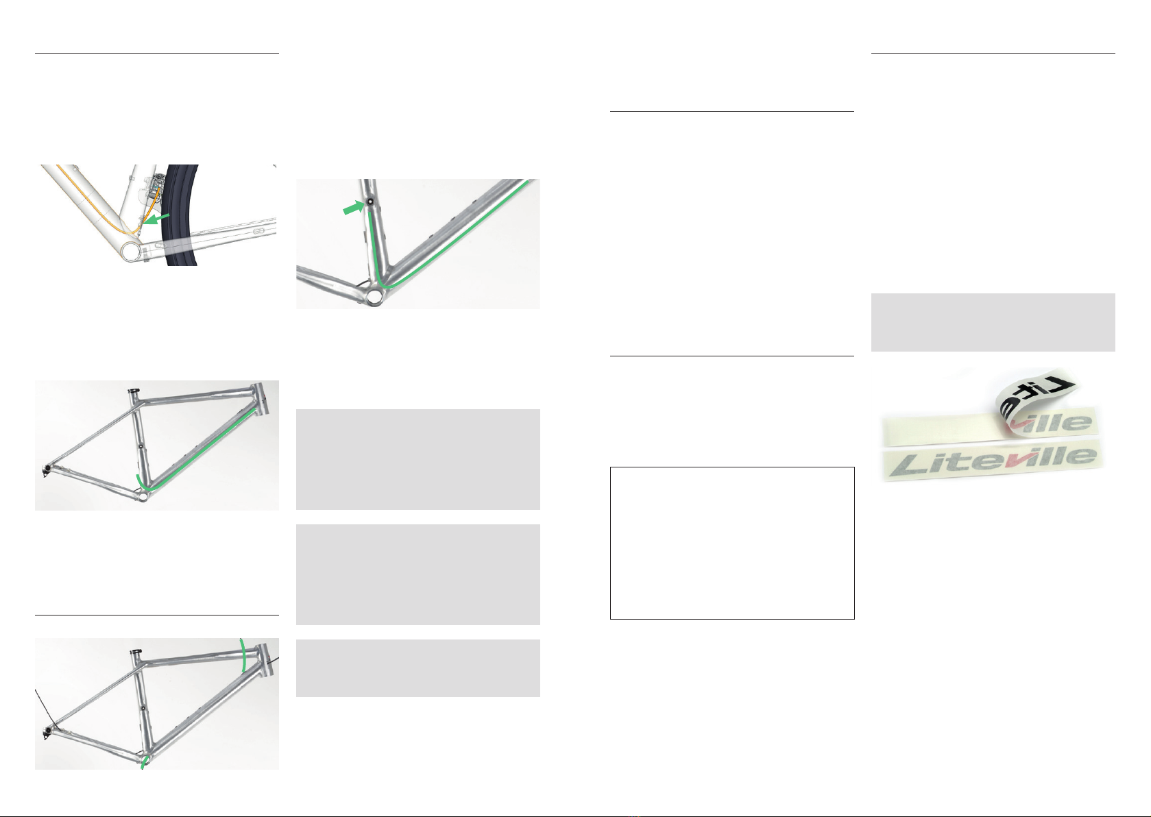
11.Variable dropper post
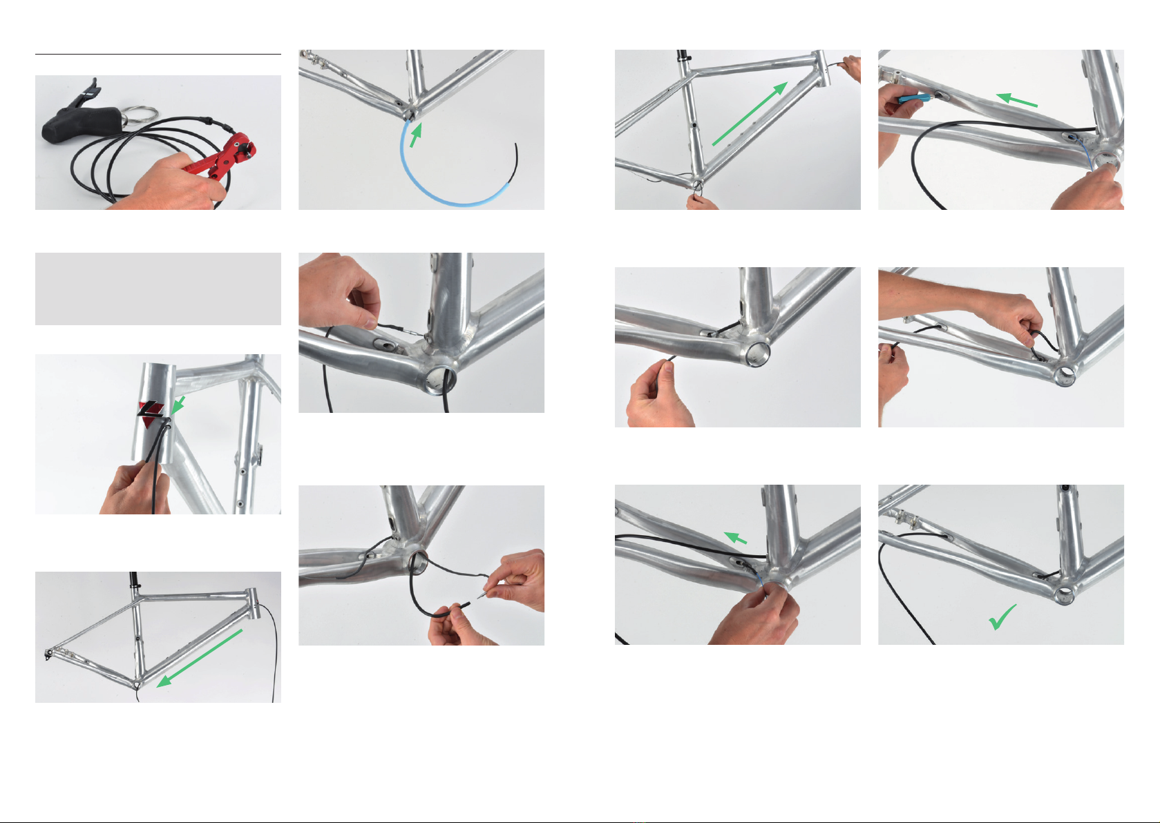
10.Cable routing front derailleur
• Push the cable housing into the right-hand,
bottom hole at the steering tube. Guide the
housing through the down tube and have it exit
at the bottom bracket.
• From the bottom end, slip a foam tube over the
cable housing.
• Have the end of the cable housing exit at the
rear end of the seat tube.
• Install the black cable guidance and tighten
the screw at the frame cable exit hole.
• Cut the end of the cable housing with specific
Bowden cable pliers and connect it with the
front derailleur.
• Insert the cable housing or hydraulic hose into
the cable hole at the down tube, close to the
steering tube. Push the housing into the down
tube and have it exit at the right hand of the
bottom bracket.
• Now slip a foam tube over the bottom bracket
all the way to the top end of the housing, close
to the steering tube.
• From the bottom, push the housing into the
seat tube.
• For the assembly and installation of the vari-
able dropper post, stick to the manufacturers’
manuals.
NOTE: depending on the handlebar width,
the number of spacers underneath the stem,
the frame size and the length of the cable,
the cable housing or the hydraulic hose can
alternatively exit the frame at the right-hand
cable hole next to the steering tube.
NOTE: the seat tube is specifically
prepared for the installation of an Eightpins
variable dropper post with very precisely
manufactured, small tolerances. The
measurements of the frame including the
inner tube diameter must not be altered.
NOTE: in case the frame is painted or ano-
dized, the internal diameter of the seat tube
within the first 140 must not be altered.
E. MAINTENANCE AND CARE
1. Headset bearing
With normal usage, the bearings of the headset
do not have to be dismounted or greased.
In case you notice a defect bearing anyways, you
may order the specific bearing in your Liteville
WorksStation or directly at Syntace.
Never point at your bearings with a high-pres-
sure water jet as this can easily damage them.
After all, too much “maintenance” may even
harm your bearings.
2. Screws
The screws in your frame are all made from
Titanium or Aluminum and are produced
specifically for Liteville frames. They are all
mounted with screwlock. Nonetheless, you are to
check the correct tightening torque frequently.
ADVICE: in case a screw can actually be
twisted as the tightening torque is che-
cked, the screwlock is broken and as a
consequence needs to be exchanged. The
screw needs to be secured again. Unscrew
it, clean it and reassemble everything with
screwlock.
We have summed up a “Screwlock Basics”
at www.liteville.de > FAQ.
3. WorksFinish surface
The Liteville WorksFinish is a genuine raw Alu-
minum surface, free of any kind of protection
paint, meaning it is no Aluminum simulation. The
frame actually shows the signs of the original ma-
nufacturing process. Stains are thus common, the
frame may even change its color slightly which
leads to the natural charm of a grown patina.
The surface can be reprocessed at all times either
chemically or mechanically with a Scotch-Bri-
te-Finish or by being polished manually. The
frame comes standard with two Scotch-Brite
grinding fleeces. Try applying it on a spot that is
not seen directly.
NOTE: The WorksFinish frame comes with
3M stickers. It is your choice if you put them
on your frame or if you do not.
Picture shows Liteville stickers.

- 20 - - 21 -
4ONE MK1
ITEM NO.
Description
Article No.
QTY.
1
BB_40x52x9_45x45_4RS_cone
147843 1
2
Baseplate-cone_1.5_39.8
127159 1
3
BB_30x41x6.5_2RS_cone
103870 1
4
Topplate-cone_1-1-8
127166 1
5
VarioSpin-Top-seal_1-1-8
127210 1
6
VarioSpin-Top-Cap_1-1-8
127173 1
7
O-Ring_28.6x2.0
127203 1
8
X-12_hanger_screw_Typ2_26mm
116849 2
9
X-12_thread-insert_0mm
105683 1
10
X-12_hanger_Typ3_Std
128118 1
11
FD-mount_setback_CL45
147850 1
12
screw_M5x10_flat-head_HEX4
147862 2
13
Mounting_Pin_Assembly
153103 1
13.1
Cylinder-Tool
1
13.2
Mounting_Pin_V2
1
13.3
SW10
1
13.4
Axle_Fixing_Ring
1
13.5
Adjusting_Ring_V2
1
14
X-12_axle_assembly_142mm_allen-key
1
14.1
X-12_axle_142mm
105645 1
14.2
X-12_stainless-steel_washer 12mm
127098 1
14.3 X-12_axle_end-plug
127104 1
14.4 X-12_axle_cone
127111 1
14.5
X-12_axle_O-ring_small
127128 1
15
screw_Al_M5x16_TX25
153400 7
16
cable-inlet_closed_Typ2
148246 2
17
cable-inlet_single_Typ2
148253 2
18
screw-sc_M3x6_HEX2
148260 2
19
CS-protector_top_4-ONE
1
7
6
5
4
3
1
13.413.313.1
11
12
12
14.5 14.2 14.4
910
8
15
15
2
15
15
13.2 13.5
17
18
16
15
15
18
17
16
8
15
14.1 14.3
LV-4-ONE_MK01_Anzugsmomente_S_anleitung.pdf 1 08.07.2019 13:17:25
LV-4-ONE_MK01_Anzugsmomente_S_anleitung.pdf 2 08.07.2019 13:17:25
SPARE PARTS

- 22 - - 23 -
NOTESNOTES

- 24 -
GmbH
Dammweg 1 · D- 83342 Tacherting · Germany
Tel. +49 (0)8634 66666 · Fax +49 (0)8634 6365
syntace@syntace.de
www.syntace.de
Am Mühlbach 12b · 87487 Wiggensbach · Germany
Tel. +49 (0)8370 929988 · Fax +49 (0)8370 929888
office@liteville.de
www.liteville.de
Table of contents
Other Liteville Bicycle Accessories manuals