Lithium Grim Purple Octave Instruction Manual

Purple Octave
Building instructions
V1.1

Purple Octave v1.1
Manufacturer and product names are mentioned solely for circuit identification, and where applicable their trademarks are the
property of their respective owners who are in no way associated or affiliated with the author. No cooperation or endorsement
is implied.
2
Table of contents
Components .......................................................................................................................................3
PCB layout ..........................................................................................................................................3
Bill of Materials...................................................................................................................................3
Introduction........................................................................................................................................5
Building sequence...............................................................................................................................5
Off board wiring..................................................................................................................................6
Troubleshooting .................................................................................................................................7
Schematic...........................................................................................................................................8
Read this entire manual thoroughly before you start building the effect!
Last update: 17-12-2016

Purple Octave v1.1
Manufacturer and product names are mentioned solely for circuit identification, and where applicable their trademarks are the
property of their respective owners who are in no way associated or affiliated with the author. No cooperation or endorsement
is implied.
3
50 mm x 50 mm
1.97 in x 1.97 in
Components
ID
Value
Comment
ID
Value
Comment
C1
10n
SMF/MKT
R1
2M2
1% metal film
C2
470p
Ceramic
R2
820k
1% metal film
C3
22u
Electrolytic
R3
680k
1% metal film
C4
1n
Ceramic
R4
180k
1% metal film
C5
22u
Electrolytic
R5
100k
1% metal film
C6
100n
SMF/MKT
R6
220R
1% metal film
C7
10n
SMF/MKT
R7
220R
1% metal film
C8
22u
Electrolytic
R8
39k
1% metal film
C9
22u
Electrolytic
R9
47k
1% metal film
C10
10n
SMF/MKT
R10
39k
1% metal film
C11
10n
SMF/MKT
R11
330k
1% metal film
C12
100n
SMF/MKT
R12
470k
1% metal film
C13
100u
Electrolytic
R13
10k
1% metal film
C14
100n
SMF/MKT
R14
2M2
1% metal film
D1
1N5817
R15
10k
1% metal film
D2
1N4148
R16
820k
1% metal film
D3
1N4148
R17
100k
1% metal film
Q1
2N3906
R18
2M2
1% metal film
Q2
MPSA13
R19
2M2
1% metal film
Q3
MPSA13
R20
10k
1% metal film
Q4
MPSA13
R21
150k
1% metal film
R22
4k7
1% metal film
VR1
C10k
Drive
VR2
A1M
Volume
PCB layout
A=Log, B=Lin, C=Rev. Log

Purple Octave v1.1
Manufacturer and product names are mentioned solely for circuit identification, and where applicable their trademarks are the
property of their respective owners who are in no way associated or affiliated with the author. No cooperation or endorsement
is implied.
4
Bill of Materials
Capacitors
Value
Amount
Type
Rating
470p
1
Ceramic
16V +
1n
1
SMF/MKT
16V +
10n
4
SMF/MKT
16V +
100n
3
SMF/MKT
16V +
22u
4
Electrolytic
16V +
100u
1
Electrolytic
Diode
Transistors
Value
Amount
Value
Amount
1N5817
1
2N3906
1
1N4148
2
MPSA13
3
Resistors (1% metal film)
Value
Amount
Value
Amount
220R
2
330k
1
4k7
1
470k
1
10k
3
680k
1
39k
2
820k
2
47k
1
2M2
4
100k
2
150k
1
C10k reverse logarithmic
1
180k
1
A1M logaritmic
1

Purple Octave v1.1
Manufacturer and product names are mentioned solely for circuit identification, and where applicable their trademarks are the
property of their respective owners who are in no way associated or affiliated with the author. No cooperation or endorsement
is implied.
5
Introduction
The Purple Fuzz is a personal take on the classic Octave Fuzzes. It has been specially adapted so it will
fit on a small pcb with integrated 3PDT footswitch. If you want it as original as possible you can leave
out D1 and jumper it with a spare piece of lead wire. Be warned that you will not have polarity
protection anymore if you leave out D1. If you want to leave out the LED than do not solder R22 and
the LED.
Building sequence
Soldering this board can be very complicated for some people since the solder pads are very close
together. Use a magnifying glass to make the job easier. If you want to experiment with other
transistors then you could socket them instead of soldering them to the board. You’ll need a 20 SIL,
break off the sockets and solder them to the board.
Start by soldering the resistors. If you want to socket the transistors then solder the sockets now.
Note: Do not blow on your solder in an attempt to cool it down. That will possibly result in a bad join
that might corrode!
Solder D1, the ceramic capacitors and then the small SMF/MKT capacitators, D2 and D3, then the
electrolytes, finish by soldering the 3PDT footswitch to the board. You are free to choose on which
side of the board you will solder the footswitch, just be sure to test if it fits your enclosure before you
solder it!
Place the transistors and you are almost ready to rock.
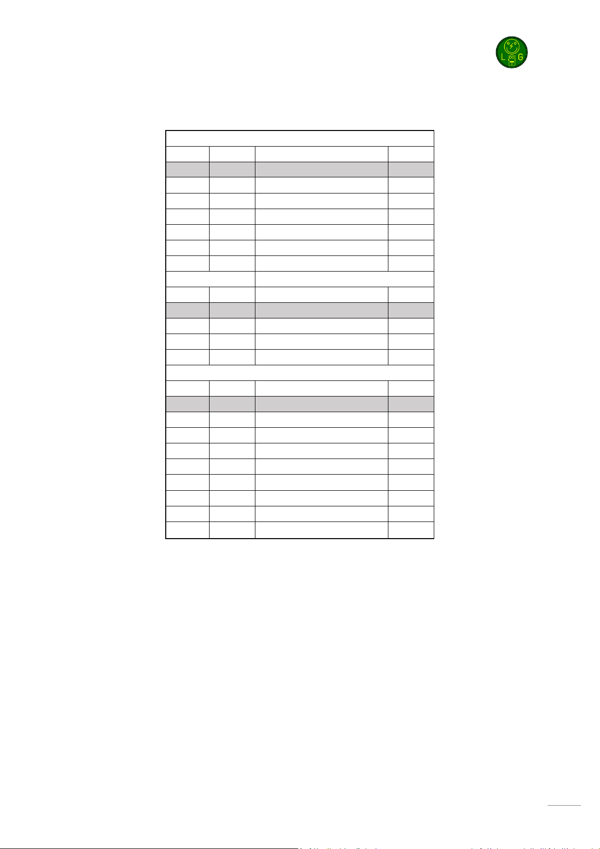
Besides the components mentioned in the Bill Of Materials table, you will need:
•2 input jacks. 2 mono jacks if you are not going to use a battery but only the 9V adapter. 1
mono (for output) and 1 stereo jack (for input) if you will be using both a 9V battery and the
9V adapter.
•1 x 3PDT footswitch (9 pins)
•2,1mm DC jack (isolated).
•9v battery clip (optional).
•22 gage stranded hook-up wire.
•1 x LED for status
•Hammond 1590B case (or similar) in your favorite color if you make sure to use the smallest
possible components. A 1590N1 (or 125B) will give you more space to work with so I advise
that is you have some bigger components.

Purple Octave v1.1
Manufacturer and product names are mentioned solely for circuit identification, and where applicable their trademarks are the
property of their respective owners who are in no way associated or affiliated with the author. No cooperation or endorsement
is implied.
6
Off board wiring
Wiring the pots VR1-VR2 is very simple. The rectangle pad marks pin 1 of a potentiometer. The
images below show how you can recognize which pin is which on a potentiometer.
After wiring the potentiometers you will need to wire the input, output and LED :
S
Cathode (short leg)
Anode (long leg)
Ring
Sleeve
Tip
Tip
Sleeve
Input Jack Output Jack
Blue = pin 1
White = pin 2
Yellow = pin 3
3 2 1
1 2 3

Purple Octave v1.1
Manufacturer and product names are mentioned solely for circuit identification, and where applicable their trademarks are the
property of their respective owners who are in no way associated or affiliated with the author. No cooperation or endorsement
is implied.
7
Troubleshooting
All PCB’s have been 100% factory e-tested and out of every batch I receive I build an effect to double
check, so there should not be a connection problem on the PCB itself.
The board is not working (at all), what now?
•Check if your 9V is plugged in correctly (and/or soldered correctly on the board).
•Check that you oriented the capacitors, IC’s ,transistors and diodes the right way. SMF, MKT
and ceramic capacitors as well as resistors do not need to be oriented.
•Check if you used the correct values of the components. For resistors you can look here:
http://www.diyaudioandvideo.com/Electronics/Color/
•Double and triple check your soldering! A loose or cold solder can be really bad for your
board.
•Replace the IC, it might be defective. Before doing that first unplug the 9V and wait for 5
seconds.
•Check that you have good/high grade components. A lot of Chinese sourced parts are fakes
(especially high end opamps, vintage diodes and transistors) so be careful that you source
your parts from reliable suppliers.

Purple Octave v1.1
Manufacturer and product names are mentioned solely for circuit identification, and where applicable their trademarks are the
property of their respective owners who are in no way associated or affiliated with the author. No cooperation or endorsement
is implied.
8
Schematic
Table of contents
Other Lithium Grim Music Equipment manuals