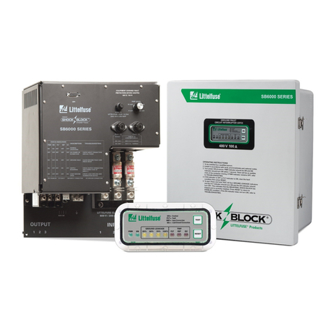
Littelfuse Industrial Shock Block SB5000 Series User manual

Tel: +1-800-832-3873
E-mail: [email protected]
www.littelfuse.com/SB5000
SB5000 MANUAL
INDUSTRIAL SHOCK BLOCK
®
REVISION 1-B-101821
Copyright © 2021 by Littelfuse, Inc.
All rights reserved.

SB5000 Industrial Shock Block Page i
Rev. 1-B-101821
This page intentionally left blank.

SB5000 Industrial Shock Block Page ii
Rev. 1-B-101821
TABLE OF CONTENTS
SECTION PAGE
1 Introduction .............................................................1
1.1 General .......................................................................1
1.1.1 SB5000 GFCI ................................................1
1.1.2 SB5000 SPGFCI ...........................................1
1.1.3 SB5000 EGFPD ............................................2
1.2 Features ......................................................................2
1.3 Operator Interface .....................................................2
2 Installation ................................................................2
2.1 Mounting ...................................................................2
2.2 Supply Connections ..................................................2
2.3 Load Phase Connections ...........................................2
2.4 Ground Connections .................................................2
2.5 Load-Ground-Connection Monitor ..........................2
2.6 Trip Status Terminals ................................................3
3 Operation and Setup ...............................................9
3.1 Operator Interface Buttons ........................................9
3.1.1 Test .................................................................9
3.1.2 Reset ..............................................................9
3.2 LED Indication ..........................................................9
3.2.1 Power .............................................................9
3.2.2 Enabled ..........................................................9
3.2.3 GF Trip ..........................................................9
3.2.4 GC Status .......................................................9
3.3 Settings.................................................................... 10
3.3.1 Termination Device Type (Switch 1) ........... 10
3.3.2 GC Reset Mode (Switch 2) ........................... 10
3.3.3 GF Reset Mode (Switch 3) ........................... 10
3.3.4 PWR Loss Mode (Switch 4) ......................... 10
3.4 Input Connection .................................................... 10
3.5 Undervoltage, Overvoltage and Chatter Detection 10
3.6 Temperature Limit Trip ......................................... 10
3.7 Contactor Monitoring ............................................. 10
3.8 Ground-Fault Detection ......................................... 10
3.9 Load-Ground-Connection Monitor ....................... 10
3.10 UL 943 Self-Test and UL 1998 Requirements ..... 11
4 UL 943C Requirements ....................................... 12
4.1 Trip Time ................................................................ 12
4.2 Grounding Circuit .................................................. 12
4.3 Grounding Monitor/Interrupter .............................. 12
5 Troubleshooting .................................................... 13
6 Technical Specifications ...................................... 14
6.1 SB5032 Series ........................................................ 14
6.2 SB5060 Series ........................................................ 14
6.3 General Specifications ........................................... 14
7 Ordering Information .......................................... 16
Appendix A SB5000 Series Revision History ............... 17
LIST OF FIGURES
FIGURE PAGE
1 UL GFCI Classes ..................................................... 1
2 Three-Phase Connection Diagram
(GFCI Configuration Shown) .................................. 3
3 SB50xx-x11-0 Model (Lid not shown) ................... 4
4 SB50xx (Lid closed) ................................................. 5
5 SB50xx Outline and Mounting Details ................... 6
6 SB50xx Conduit Cutout Locations .......................... 7
7 1N5339B Zener-Diode and SE-TA6-SM
Termination Devices ................................................ 7
8 SE-TA6 Termination Assembly ............................ 8
9 SE-TA6ASF-WL Small-Format Termination
Assembly with Wire Leads .................................... 8
10 Configuration Switches .......................................... 10
11 SB5032 and SB5060 Temp Derating Curves ....... 11
12 Class-A GFCI Curve .............................................. 12
13 Class-C and -D GFCI Curve .................................. 12
LIST OF TABLES
TABLE PAGE
1 Power and Trip Status LEDs ................................... 9
2 Status LED Troubleshooting ................................. 13
DISCLAIMER
Specifications are subject to change without notice.
Littelfuse is not liable for contingent or consequential
damages, or for expenses sustained as a result of incorrect
application, incorrect adjustment, or a malfunction.

SB5000 Industrial Shock Block Page iii
Rev. 1-B-101821
This page intentionally left blank.

SB5000 Industrial Shock Block Page 1
Rev. 1-B-101821
1 INTRODUCTION
1.1 GENERAL
The SB5000 Industrial Shock Block is available as a
ground-fault circuit interrupter (GFCI), special-purpose
ground-fault circuit interrupter (SPGFCI), or as an
equipment ground-fault protective device (EGFPD). All
types operate within the time-current curve defined by UL
943 and CSA C22.1 for Class A GFCIs.
The SB5000 is available for voltages from 208 to 600
V and are continuously rated at either 32 or 60 A. SB5000
models have NEMA-4X and IP69K ratings and are UL-
listed.
The following model types are available:
GFCI Class A with a 6 mA fixed trip level
SPGFCI Class C with a 20 mA fixed trip level
SPGFCI Class D with a 20 mA fixed trip level
EGFPD with selectable trip-level settings from 6
to 100 mA
Class A GFCIs are UL 943 listed.
Class C and Class D SPGFCIs are UL 943C listed.
EGFPD models have adjustable trip-level settings from
6 to 100 mA and are UL 943 and UL 1053 listed.
1.1.1 SB5000 GFCI
GFCI models are permanently-connected GFCIs that
meet the requirements of the UL 943 definition for Class A
devices, with a fixed 6-mA trip level. It is available only for
208 Vac systems.
1.1.2 SB5000 SPGFCI
SPGFCI models are permanently-connected special-
purpose GFCIs that meet the requirements of UL 943C
definitions for Class C and Class D devices, with a fixed
20-mA trip level. These classes extend GFCI protection
beyond the standard 6-mA Class-A GFCI and are
appropriate for many industrial and commercial
applications.
Special-purpose SB5000 GFCIs (Class C or Class D)
can be used in the following applications:
3-Phase Grounded-neutral systems where voltage to
ground is above 150 Vac and equipment grounding or
double insulation is required by the National Electrical
Code (NEC) and ANSI/NFPA 70.
3-Phase Grounded-neutral systems where voltage to
ground is 150 Vac or less and equipment grounding or
double insulation is provided, but the use of a Class A
ground-fault circuit interrupter is not practical.
Any 3-Phase CEC application in which a Class A
GFCI is not required.
The UL GFCI classes and their intended applications
are shown in Fig. 1.
The SB5000 also provides ground-connection
monitoring as required by UL 943C. The ground-
monitoring function automatically disconnects the supply
if the load is not properly bonded to ground, and requires
a cable pilot wire and a termination device installed at the
load. The SB5000 will not allow its contactor to close on
power-up and will open the contactor if the load ground is
not connected. See Fig. 2.
If required by the application, a load-ground-
connection monitor feature can be enabled for Class A
GFCI models. See Section 2.5.
FIGURE 1. UL GFCI Classes.
Over 240 V
Line Voltage
Equipment
Grounding or
Double
Insulation
1
Over 480
2
Class C
Class A Class D
3
No Yes
NoYe s
No Ye s
NOTES:
1. May be provided but not required.
2. Equipment grounding or double insulation is required by the NEC Sections
250-110 (6) & 250-114 (2).
3. Low-impedance grounding path is required.Therefore, oversized
equipment grounding conductor shall be provided. Refer to Section 4.2.
4. Class E not shown.

SB5000 Industrial Shock Block Page 2
Rev. 1-B-101821
1.1.3 SB5000 EGFPD
EGFPD models can be set to trip at
6 mA or from 10 to 100 mA in increments of 10 mA, and
meet the requirements of UL 943 and
UL 1053. The adjustable trip level can help prevent
nuisance tripping in some applications.
If required by the application, a load-ground-
connection monitor feature can be enabled for EGFPD
models. See Section 2.5.
1.2 FEATURES
UL 943 inverse time curve reduces the probability of
nuisance tripping.
UL 943 fixed trip level (Class A GFCI models)
provides protection meeting NEC 210.8 (B) for
commercial kitchens, wet areas, and other
applications.
UL 943C fixed trip level (GFCI models) provides
protection for systems with leakage current higher
than the 6-mA trip level required by Class A GFCIs.
Selectable trip levels (EGFPD models) help reduce
nuisance tripping by allowing users to adjust the trip
level in systems that have leakage current higher than
UL 943 Class A 6-mA trip level, or UL 943C Class C
or D 20-mA trip level.
UL 943C ground-connection monitoring ensures
continuity of the load ground.
Undervoltage, brown-out and chatter detection
prolong the internal contactor lifetime.
Meets UL 1998 requirements.
Self-test feature continuously monitors hardware to
ensure safe operation.
Conformally coated circuit boards.
1.3 OPERATOR INTERFACE
The operator interface includes LED status indication
including the following:
- POWER
- ENABLE
- GF TRIP
- GC STATUS
- TEST and RESET buttons
2. INSTALLATION
The SB5000 is considered to be a permanently mounted
GFCI/EGFPD and should be attached to a wall or other
suitable mounting surface.
The connection diagram for three-phase systems is
shown in Fig. 2. Ensure that all conductors have the
required voltage and current ratings necessary for the
application. SB5000 installation should be performed by
a qualified person.
2.1 MOUNTING
Install SB5000 models in the correct orientation as
shown in Fig. 5, and refer to the ‘This Side Up’ label
attached to the side of the enclosure.
Enclosed models ship with no cable entry points
predrilled. Appropriate holes must be made in the
enclosure and fitted with NEMA-4X-rated (and IP69K-
rated when required) fittings for the installation of all
conductors. Space is left near the bottom or lower sides
of the enclosure to install the wiring. See Figs. 3 and 6.
2.2 SUPPLY CONNECTIONS
The supply phases are marked Input A, B, and C on the
base of the chassis as shown in Fig. 3. Use a flat-blade
screwdriver to tighten the input connections. Torque the
input terminals as described in Section 6. The input
terminals will accept 4 to 18 AWG copper wire
conductors.
2.3 LOAD PHASE CONNECTIONS
The load phases are marked Output A, B, and C on the
base of the chassis as shown in Fig. 3. Use a flat-blade
screwdriver to tighten the output connections. Torque the
output terminals as described in Section 6. The output
terminals will accept 4 to 18 AWG copper wire
conductors.
2.4 GROUND CONNECTIONS
Connect the supply and load ground conductors to the
chassis bonding point ()as shown in Fig. 3. Use a flat-
blade screwdriver to tighten the ground connections.
Torque the ground terminals as described in Section 6.
The ground terminals will accept 14 to 1/0 AWG (2.08 to
53.5 mm2) conductors.
2.5 LOAD-GROUND-CONNECTION MONITOR
An insulated pilot wire from the SB5000 to the load,
and a termination device located at the load are required
to monitor the load-ground connection. Total pilot wire
and ground wire resistance must be less than 28 ohms (trip
resistance is 38 ohms). Outline dimensions and mounting
details for compatible termination devices are shown in
Figs. 7, 8, and 9.
This monitoring function is required for Class C and
Class D GFCI models installed in NEC applications, and
can be implemented if desired for Class A GFCI or
EGFPD models.
Use only a Littelfuse termination device as others may
not meet performance requirements. Each SB5000 GFCI
is supplied with a 1N5339B termination device. Install
the termination device at the load to complete the ground-
connection loop as shown in Fig. 2. Connect terminal G
of the termination device to the equipment frame so that
the ground-conductor-to-equipment-frame connection
will be included in the monitored loop. Connect terminal
GC of the termination device to the pilot wire, and connect

SB5000 Industrial Shock Block
Page 3
Rev. 1-B-101821
the other end of the pilot wire to the SB5000 terminal GC.
Leave terminal REF unconnected in this configuration.
Class A GFCI and EGFPD models include a 1N5339B
termination device installed at the GC and REF terminals.
The termination device should remain installed at the GC
and REF terminals if the load-ground-connection
monitoring feature is not required. See Fig. 3.
2.6 Trip Status
Terminals
A normally-open contact (labeled TRIP STATUS) is
provided on all models. This contact, rated at 1 A,
24 Vac/Vdc, follows the state of the internal contactor.
See Figs. 2 and 3.
FIGURE 2. Three-Phase Connection Diagram (GFCI
Configuration Shown).

SB5000 Industrial Shock Block
Page 4
Rev. 1-B-101821
FIGURE 3. SB5060-x11-0 Model (Lid not shown).

SB5000 Industrial Shock Block
Page 5
Rev. 1-B-101821
FIGURE 4. SB50xx (Lid closed).

SB5000 Industrial Shock Block Page 6
Rev. 1-B-101821
FIGURE 5. SB50xx Outline and Mounting Details.

SB5000 Industrial Shock Block
Page 7
Rev. 1-B-101821
FIGURE 6. SB50xx Series Conduit Cutout Locations.
FIGURE 7. 1N5339B Zener-Diode and SE-TA6-SM Termination Devices.
69.9
(2.75)
GGC
TERMINATION MUST
BE INSTALLED AT
LOAD.
G
1N5339B
0.25” - 28 UNF
SE-TA6-SM
GGC
35.0
(1.38)
250 (9.84) LENGTH OF # 14 AWG
YELLOW STRANDED WIRE
NOTES:
1. DIMENSIONS IN MILLIMETRES (INCHES).
2. CAN BE IMMERSED IN GLYCOL.
10.0
(0.40)

SB5000 Industrial Shock Block Page 8
Rev. 1-B-101821
FIGURE 8. SE-TA6 Termination Assembly.
FIGURE 9. SE-TA6ASF-WL Small-Format Termination Assembly with Wire Leads.
G
GC
SE-TA6
TERMINATION
ASSEMBLY
40.0
(1.57)
67.0
(2.64)
4.5 (0.18) Ø, C’BORE 10.0 (0.39) Ø
3.2 (0.13) DEEP
41.5
(1.63)
22.2
(0.87)
10.5
(0.41)
40.0
(1.57)
19.0
(0.75)
8.0
(0.31)
TAP M4
OR 8-32
51.0
(2.01)
67.0
(2.64)
FRONT SIDE MOUNTING DETAIL
NOTES:
1. DIMENSIONS IN MILLIMETRES (INCHES).
2. TERMINAL-BLOCK SCREWS: 6-32 x 0.25.
3. MOUNTING SCREWS: M4 OR 8-32.
4. ENCLOSURE IS ELECTRICALLY CONNECTED
TOTERMINAL G.
5. CAN BE IMMERSED IN GLYCOL.
NOTE 2
4.0
(0.16)
50.8
(2.00)
12.7
(0.50)
3.2
(0.13)
MOUNTING DETAIL
12.7
(0.50)
SIDE
58.8
(2.32)
19.0
(0.75)
GC
300 (12) OF
YELLOW WIRE
G
300 (12) OF
GREEN/YELLOW WIRE TOP
NOTES:
1. DIMENSIONS IN MILLIMETRES (INCHES).
2. MOUNTING SCREWS M3.5 OR 6-32.
3. CAN BE IMMERSED IN GLYCOL.
LR 53428
US
C
R
Rev:
SE-TA6ASF-WL
SE-TA6ASF-WL
Serial No:
01
DE130600619
Rating: 5.6 Vdc @ 105 mA 12 W Max
Use with: SE-134, SE-134C, SB6100
TERMINATION ASSY

SB5000 Industrial Shock Block Page 9
Rev. 1-B-101821
3. OPERATION AND SETUP
NOTE: When its input terminals become energized, the
SB5000 powers up in RESET mode (default setting) and
the connected circuit will be energized after a brief system
test. See Section 3.3. for additional configuration settings.
3.1 OPERATOR INTERFACE BUTTONS
3.1.1 TEST
The TEST button is used to de-energize the load and to
test the SB5000 ground-fault detection circuit, indication,
and contactor. When the TEST button is pressed for one
second, the GF TRIP LED will turn ON, the ENABLE
LED will turn OFF, and the SB5000 will trip.
3.1.2 RESET
The RESET button is used to reset the SB5000 after a
ground fault has occurred and to energize the load. When
the RESET button is momentarily pressed and there are
no fault conditions present, the contactor will close and
the ENABLE LED will be ON. If the SB5000 trips
immediately after a reset, a ground fault is still present.
3.2 LED INDICATION
3.2.1 POWER
The green LED labeled POWER indicates the presence
of supply voltage.
3.2.2 ENABLED
The green LED labeled ENABLE indicates that the
contactor is closed. An audible sound from the internal
contactor can be heard each time the contactor opens or
closes.
When supply voltage is applied to the SB5000, the
SB5000 closes the contactor after approximately 10 s if
there are no fault conditions present.
3.2.3 GF TRIP
The red LED labeled GF TRIP provides ground-fault
trip indication.
If the GF TRIP LED is on, the unit has tripped. One or
more conditions may have caused a trip. If the GF TRIP
LED is flashing, the SB5000 has detected an
undervoltage, overvoltage, chatter, or temperature limit
condition. See Table 1 and Sections 3.5 and 3.6.
3.2.4 GC STATUS
The dual-color red and green LED labeled GC
STATUS provides ground-continuity indication.
If the GC STATUS LED is red, the unit has tripped.
One or more conditions may have caused a trip. If the GC
STATUS LED is flashing red, one of the following has
occurred: GC Short, Incorrect Termination, Induced AC
Voltage Trip, or a Termination Type change. See Table 1
and Sections 3.5 and 3.6.
If the GC STATUS LED is green, the load ground is
connected. See Table 1 and Section 3.9.
TABLE 1. POWER AND TRIP STATUS LEDS.
LED STATE DESCRIPTION
POWER ON Unit Powered
OFF Unit Not Powered
ENABLE ON Load Connected
OFF Load Not Connected
GF TRIP
ON Unit Tripped
OFF Unit Not Tripped
Flash
Contactor drop-out due to an
undervoltage condition, flash code
1 S
–
1 L
Flash
Contactor drop-out due to
overvoltage condition, flash code
1 S
–
1 L
Flash
Contactor drop-out due to
chattering condition, flash code
3 S
–
1 L
Flash
Contactor drop-out due to an over-
temperature condition, flash code
2 S
–
1 L
GC
STATUS
ON
(
Green
)
Load ground connected (when
used
)
ON (Red)
Load ground not connected.
Resistance is greater than 38 ohms.
This LED will also be ON during
the GC validation process.
Flash GC Short Detected
1 S
–
1 L
Flash Incorrect Termination Detected
2 S
–
1 L
Flash Induced AC Voltage Trip
3 S
–
1 L
Flash
Termination Type Change (Dip
Switch 1)
4 S
–
1 L
OFF Ground continuity verification in
p
ro
g
ress, or unit not
p
owered
POWER,
GF TRIP,
GC
STATUS
All three
LEDs
flashing
Internal diagnostic or Self-Test Fail
has been detected

SB5000 Industrial Shock Block Page 10
Rev. 1-B-101821
3.3 SETTINGS
The GFCI models have a fixed 6 mA (Class A) or 20
mA (Class C and D) trip-level value.
The EGFPD models can be set to trip at 6 mA, or from
10 to 100 mA in increments of 10 mA. The TRIP LEVEL
(mA) rotary selection switch is located on the chassis front
panel.
All models include four configuration switches that
provide additional selections. Default settings are shown
in Fig. 10.
FIGURE 10. Configuration Switches.
3.3.1 Termination Device Type (Switch 1)
The ZENER diode termination is recommended for all
applications that require load-ground connection
monitoring. The SB5000 senses this termination as a
valid end-of-line device and allows both open-circuit and
short-circuit detection. The SB5000 is M421 compliant
when used with a zener diode termination.
If a simpler option is required when the zener diode
cannot be used, the CONTINUITY ONLY mode can be
selected. This mode detects continuity between the pilot
wire and ground.
3.3.2 GC Reset Mode (Switch 2)
When set to AUTO, the SB5000 will automatically
energize when a valid termination is detected and there are
no other trips present.
When set to LATCHING GC RESET, the SB5000 will
remain de-energized when a GC Trip occurs. A GC Trip
will also be retained when power is removed. Press
RESET to clear the GC Trip.
3.3.3 GF Reset Mode (Switch 3)
Regardless of the GF Reset Mode, a GF Trip will
always remain latched until it is manually reset.
When set to AUTO, a GF Trip will be cleared after
cycling power.
When set to LATCHING GF RESET, a GF Trip will
not be cleared after cycling power.
3.3.4 PWR Loss Mode (Switch 4)
When set to AUTO, a Temperature Limit trip will
automatically reset when the internal temperature sensor
returns to a normal temperature range.
When set to AUTO, a Chatter Detection trip,
Undervoltage trip, or Overvoltage trip will automatically
reset when the supply voltage remains in a normal range
for at least 10 s.
When set to LATCHING PWR LOSS, a Temperature
Limit trip, Chatter Detection trip, Undervoltage trip, or
Overvoltage trip will require a manual reset after returning
to a normal state.
3.4 INPUT CONNECTION
The SB5000 electronics are supplied from input phases
A and B. If either phase is not connected, the unit will
remain off with the contactor open.
3.5 U
NDERVOLTAGE, OVERVOLTAGE, AND CHATTER
DETECTION
The input voltage (phases A and B only) is always
checked before the contactor is closed. If an input
undervoltage condition is detected, the contactor will
remain open and the red GF TRIP LED will flash. The
control circuit will continuously check the input voltage
and will close the contactor when the input voltage is
within acceptable limits (if PWR Loss Mode set to
AUTO).
Undervoltage detection is provided to prolong the
lifetime of the contactor by preventing contactor chatter.
Contactor chatter occurs when the voltage applied to the
control coil is marginally lower than the minimum pull-in
voltage.
3.6 Temperature Limit Trip
The SB5000 includes an internal temperature sensor. A
Temperature Limit trip will occur if the temperature is
higher than 90°C (194°F) or lower than -40°C (-40°F).
The SB5000 can be reset when the temperature returns to
a normal temperature range of -35 to 75°C (-31 to 167°F).
3.7 CONTACTOR MONITORING
The SB5000 continuously monitors the state of the
contactor. If an incorrect state is detected, a Diagnostic
Trip will occur, the contactor will open and will remain
open until supply voltage to the unit is cycled. This
condition should never be encountered during normal
operation.
The SB5000 should be used within the specifications
listed in Section 6 to ensure correct operation.
NOTE: At room temperature, the minimum contactor pull-
in voltage is approximately 80% of the nominal voltage.
At higher temperatures, the minimum pull-in voltage is
higher than 80% of the nominal voltage.
3.8 GROUND-FAULT DETECTION
The red GF TRIP LED indicates a ground-fault trip.
The SB5000 will remain tripped until the RESET button
is pressed or supply voltage is cycled (if GF Reset Mode
is set to AUTO). See Section 3.1.2.
3.9 LOAD-GROUND-CONNECTION MONITOR
The Load-Ground-Connection Monitor (GC STATUS)
LED indicates that the load ground is open when the LED

SB5000 Industrial Shock Block
Page 11
Rev. 1-B-101821
is red.
If the load ground connect is connected, the GC
STATUS LED will turn on (GREEN).
If the load ground connection is not connected during
power-up or becomes disconnected during normal
operation, the GC STATUS LED will turn ON (RED) and
the contactor will open.
The SB5000 continuously monitors the load ground
and will automatically close the contactor if the load-
ground connection is restored (if GC Reset Mode is set to
AUTO).
N
OTE
: Load-ground-connection monitoring is only
required for GFCI Class C and Class D models as per UL
943C. Refer to Section 4.3 for a description of the UL
943C load-ground monitor requirements. For EGFPD and
GFCI Class A models, load-ground-connection
monitoring is optional.
3.10 UL 943 S
ELF
-T
EST AND
UL 1998 R
EQUIREMENTS
The 2015 revision to the UL 943 standard includes a self-
test requirement to verify a GFCIs ability to respond to a
ground fault. All SB5000 options include an automatic self-
test feature. If a problem is detected, the SB5000 will trip.
A Self-Test Failure will be indicated by a unique LED
pattern as described in Table 1.
A self-test is initiated a few seconds after power-up, a few
seconds after the contactor is closed, and during normal
operation.
In addition to the automatic self-test, a monthly manual
test is also recommended.
Compliance to the UL 1998 Software in Programmable
Components standard is also included.
FIGURE 11. SB5032 and SB5060 Temperature Derating Curves.

SB5000 Industrial Shock Block Page 12
Rev. 1-B-101821
4. UL 943C REQUIREMENTS
The following sections contain excerpts from the
UL 943C(1) Standard for Class C and D applications. For
EGFPD models, only Section 4.1 applies where selectable
trip levels from 6 to 100 mA are permitted
(20 mA is the only allowed trip level for GFCI devices in
NEC applications).
4.1 TRIP TIME
Class C and Class D GFCIs shall be capable of
interrupting the electric circuit to the load when the fault
current to ground (I) is within the range of a minimum of
20 mA through a maximum of (110% of the rated
voltage/500 Ω) A within the time interval (T) in
accordance with the relationship:
Where:
T is expressed in seconds, and
I is expressed in mA
Except that T is not required to be less than 20 ms.
The tripping threshold of these GFCIs shall be in the
range of 15 to 20 mA.
Fig. 14 shows the Class-A GFCI maximum-trip-time-
versus-current curve defined by UL 943 (with the above
formula); UL 943 also defines a limit to the formula, with
a minimum required trip time (or fastest trip speed) of
20 ms, which occurs at about 300 mA of ground-fault
current (I) per the formula. Class C and D GFCIs must
operate within this same curve, except that their operating
threshold is 15 to 20 mA (non-adjustable). See Fig. 15.
The SB5000 EFGPDs described in this manual also
operate within the Class-A formula, but have a 6- to
100-mA threshold setting range.
4.2 GROUNDING CIRCUIT
The equipment grounding circuit of the circuit shall be
sufficiently low impedance that, should a fault to ground
occur, the voltage resulting across the grounding circuit
shall not exceed 150 V. The size of the grounding
conductor required for a circuit shall be determined by
calculating the resistance using the following formula and
converting that value to a wire gauge based on the length
of the equipment grounding conductor:
Where:
RG is the resistance of the equipment grounding
conductor
RU is the resistance of the ungrounded conductor, and
VLG is the RMS value of the supply line to ground
voltage
Refer to UL 943C Appendix A for a sample calculation
of grounding conductor size.
4.3 GROUNDING MONITOR/INTERRUPTER
A GFCI shall be capable of detecting and causing
interruption of the circuit under both of the following
conditions:
a) An open grounding circuit, and
b) Impedance in the grounding circuit that would allow
more than a 150 volt drop in the grounding circuit.
(1) Excerpts from UL 943C are the property of
Underwriters Laboratories Inc.
FIGURE 12. Class-A GFCI Curve.
FIGURE 13. Class-C and -D GFCI Curve.
T=
1.43
20
I
()
10
0.1
20 ms
0.01
06 100 200 300
TIME (s)
CURRENT (mA)
1
10
0.1
20 ms
0.01
020 100 200 300
TIME (s)
CURRENT (mA)
1

SB5000 Industrial Shock Block Page 13
Rev. 1-B-101821
5. TROUBLESHOOTING
TABLE 2. STATUS LED TROUBLESHOOTING.
STATUS LEDS
DESCRIPTION TROUBLESHOOTING
POWER ENABLE GF
TRIP
GC
STATUS
ON ON OFF ON
(GREEN) Normal Operation ---------------
OFF OFF OFF OFF No Power to the SB5000 Check supply connection to, and power
fuses of, inpu
t
s 1 and 2.
ON OFF ON ON
(GREEN) Ground Fault Occurred Clear ground fault on the system and press
RESET.
ON OFF FLASH
1 S – 1 L
ON
(GREEN)
Contactor Drop-Out Due to
an Undervoltage,
Overvoltage, or Chattering
Condition
Verify the input voltage is within
acceptable limits and press RESET.
ON OFF FLASH
2 S – 1 L
ON
(GREEN)
Contactor Drop-Out Due to
a Temperature-Limit
Exceeded Condition
Allow the temperature to fall back to a
normal range.
ON OFF FLASH
3 S – 1 L
ON
(GREEN)
Temperature limit exceeded
Contactor Drop-Out Due to
a Chattering Condition
Verify the input voltage is within
acceptable limits and press RESET.
ON OFF OFF ON (RED) Load-Ground
Connection Open
Check load ground, pilot wire, and
termination device(1).
ON OFF OFF
FLASH
(RED)
1 S
–
1 L
GC Short detected
Check resistance between GC wire and
ground. Ensure that the resistance is
greater than 500 ohms.
ON OFF OFF
FLASH
(RED)
2 S – 1 L
Incorrect termination type
detected
Confirm that the intended termination type
is selected (see Section 3.3). If the Zener
termination type is selected, ensure that the
termination is installed correctl
y
(if used).
ON OFF OFF
FLASH
(RED)
3 S
–
1 L
Induced AC limit detected Induced AC has exceeded 10Vrms for
greater than 500ms.
ON OFF OFF
FLASH
(RED)
4 S
–
1 L
Termination type has been
changed.
Confirm that the selected termination type
(Dip Switch 1) matches the installed
termination type and press RESET.
FLASH OFF FLASH FLASH
RED Diagnostic error or Self-Test
failure
Cycle power. If error repeats, consult
factor
y
.
NOTES:
(1) If ZENER mode is selected, a zener termination device is required. If CONTINUITY ONLY mode is selected, a termination
device is not required.

SB5000 Industrial Shock Block Page 14
Rev. 1-B-101821
6. TECHNICAL SPECIFICATIONS
6.1 SB5032 Series
Voltage, Current, and Power Ratings(1):
208 Vac Option:
Voltage ................................ 3 PH, 3 wire (no neutral),
60 Hz(2), 208 Vac
(+10, -15%)
Current:
AC-1 ..................................... 32 A
AC-3 ..................................... 32 A
Breaking Capacity ........... 6 x 60 A
Making Capacity ............. 6 x 60 A
Power (AC-3) .......................... 10 hp
480 Vac Option:
Voltage ................................ 3 PH, 3 wire (no neutral),
60 Hz(2), 480 Vac
(+10, -15%)
Current:
AC-1 ..................................... 32 A
AC-3 ..................................... 32 A
Breaking Capacity ........... 5 x 60 A
Making Capacity ............. 5 x 60 A
Power (AC-3) .......................... 20 hp
600 Vac Option:
Voltage ................................ 3 PH, 3 wire (no neutral),
60 Hz(2), 600 Vac
(+10, -15%)
Current:
AC-1 ..................................... 32 A
AC-3 ..................................... 32 A
Breaking Capacity ........... 4 x 60 A
Making Capacity ............. 4 x 60 A
Power (AC-3) .......................... 15 hp
6.2 SB5060 Series
Voltage, Current, and Power Ratings(1):
208 Vac Option:
Voltage ................................ 3 PH, 3 wire (no neutral),
60 Hz(2), 208 Vac
(+10, -15%)
Current:
AC-1 ..................................... 60 A
AC-3 ..................................... 60 A
Breaking Capacity ........... 6 x 60 A
Making Capacity ............. 6 x 60 A
Power (AC-3) .......................... 20 hp
480 Vac Option:
Voltage ................................ 3 PH, 3 wire (no neutral),
60 Hz(2), 480 Vac
(+10, -15%)
Current:
AC-1 ..................................... 60 A
AC-3 ...................................... 60 A
Breaking Capacity ........... 5 x 60 A
Making Capacity .............. 5 x 60 A
Power (AC-3) .......................... 40 hp
600 Vac Option:
Voltage ................................3 PH, 3 wire (no neutral),
60 Hz(2), 600 Vac
(+10, -15%)
Current:
AC-1 ...................................... 60 A
AC-3 ...................................... 60 A
Breaking Capacity ........... 4 x 60 A
Making Capacity .............. 4 x 60 A
Power (AC-3) .......................... 25 hp
6.3 General Specifications
Trip Level Settings:
GFCI Class A ...................... Fixed 6 mA
GFCI Class C and Class D .. Fixed 20 mA
EGFPD ................................ 6, 10, 20, 30, 40, 50, 60,
70, 80, 90, and 100 mA
Trip Time .................................. Defined by:
or minimum 20 ms. See
Section 4.1.
Operating Frequency ................ 60 Hz ± 3 Hz
Wiring and Torque Requirements:
Input and Output Terminals:
Conductor Size ................. 18 to 4 AWG
....................................... (0.82 to 21.2 mm2)
Torque .............................. 16 lbf·in (1.8 N·m)
Ground Terminals:
Conductor Size ................. 14 to 1/0 AWG
(2.08 to 53.5 mm2)
Torque:
14 to 10 AWG
(2.08 to 5.26 mm2) ... 35 lbf·in (4.0 N·m)
8 AWG
(8.36 mm2) ............... 40 lbf·in (4.5 N·m)
6 to 4 AWG
(13.3 to 21.1 mm2) ... 45 lbf·in (5.1 N·m)
3 to 1/0 AWG
(26.7 to 53.5 mm2) ... 50 lbf·in (5.6 N·m)
Ground-Check and Trip Status Terminals:
Conductor Size ................ 26 to 12 AWG
(0.13 to 3.3 mm2)
Torque ............................. 5 lbf·in (0.56 N·m)
T=
1.43
20
I
()

SB5000 Industrial Shock Block Page 15
Rev. 1-B-101821
Enclosure Cover Fasteners:
Torque ............................. 20 lbf·in (2.26 N·m)
PWB Conformal Coating ......... MIL-1-46058 qualified
UL QMJU2 recognized
Ground-Check Circuit:
Open-Circuit Voltage.......... 21 Vdc
Nominal Loop Current
(Zener termination) ............. 30 mA
Maximum Loop Current ..... 40 mA
Induced-ac Withstand ......... 10 Vac
GC-Loop Trip Resistance ... 38 ± 5 Ω
GC-Loop Reset Resistance . 28 Ω
Trip Status Contact:
Contact Configuration ........ Normally Open (N.O.)
UL Rating ........................... 1 A Resistive, 24 Vac;
1 A Resistive, 24 Vdc
Security:
Enclosure ............................ Lockable latch
Short-Circuit Current
Rating ...................................... 10 kA,
Test Information ....................... Tested with Littelfuse K5
input fuses installed. K5
fuses have a short-circuit
current rating of 50 kA
Fuse Requirements:
Input Fuses (not included):
Fuse Rating ...................... 60 A, 600 Vac, Class K5
or RK5
Fuse Part Number ............ Littelfuse 0NLS060.T or
FLSR060.T
Enclosure .................................. NEMA 4X, IP69K
Polycarbonate,
Lockable
Dimensions:
Height ................................. 285.7 mm (11.2 in.)
Width .................................. 244.3 mm (9.6 in.)
Depth .................................. 119.6 mm (4.7 in.)
Shipping Weight:
All Models ............................. 4.5 kg (10 lb)
Environment:
Operating Temperature:
UL Rating ...........................-35 to 66°C (-31 to 151°F)
Operating Range .............. -35 to 75°C (-31 to
167°F)
Maximum Internal Temp
Limit: .................................. 90°C (194°F)
Minimum Internal Temp
Limit: .................................. -40°C (-40°F)
Temperature derating ............See Fig. 11
Storage Temperature .............-55 to 80°C (-67 to 176°F)
Humidity ................................93% Non-Condensing
Altitude ..................................2,000 m (6,562 ft)
maximum
Certification:
All Models .......................... UL1998
GFCI:
Enclosed:
Class A .......................... UL 943 listed
Class C .......................... UL 943C listed
Class D .......................... UL 943C listed
EGFPD:
Enclosed ........................... UL 943/UL 1053 listed
To: UL 943 Ground-Fault Circuit-Interrupters
UL 943C Special Purpose Ground-Fault Circuit-
Interrupters
UL 1053 Ground Fault Sensing and Relaying
Equipment
UL 1998 Software in Programmable Components
NOTES:
(1) IEC 60947-1 Annex A defines several utilization
categories. AC-1 refers to non-inductive or slightly
inductive loads. AC-3 refers to squirrel-cage motors.
(2) UL 943 and UL 943C does not apply to 50-Hz
installations.

SB5000 Industrial Shock Block
Page 16
Rev. 1-B-101821
7. O
RDERING
I
NFORMATION
Termination Assemblies
(1)
:
1N5339B ...................................... 5-W Axial Lead
Termination Device
SE-TA6 ........................................ 50-W Termination
Assembly
SE-TA6-SM ................................. 50-W Stud-Mount
Termination Assembly
SE-TA6ASF-WL......................... 12-W Small Format
Termination
Assembly with Wire
Leads
NOTES:
(1)
All SB5000 models include a 1N5339B Termination
Device.
This manual suits for next models
17
Table of contents
Other Littelfuse Industrial Equipment manuals
Popular Industrial Equipment manuals by other brands
Filtration Group
Filtration Group Air System Products Robo-Drain RD13 Installation & operation manual

King Industrial
King Industrial Excelsior Duo-Fence XL-U30 instruction manual

Planeta
Planeta HD3N-EX Operation and maintenance manual
Re
Re WG251 SKB-B RESMART Installation, use and maintenance
Toku
Toku MG-7206BSET manual
Hydac
Hydac CTM-SC-3 Series installation manual
