Milltronics AIRANGER DPL PLUS User manual

AIRANGER DPL PLUS
Instruction Manual PL-508 March 2001
AIRANGER DPL PLUS
33455080
Rev. 2.5

© Siemens Milltronics Process Instruments Inc. 2001
Safety Guidelines
Warning notices must be observed to ensure personal safety as well as that of others, and to protect the product and the connected equipment.
These warning notices are accompanied by a clarification of the level of caution to be observed.
Qualified Personnel
This device/system may only be set up and operated in conjunction with this manual. Qualified personnel are only authorized to install and
operate this equipment in accordance with established safety practices and standards.
Warning:This product can only function properly and safely if it is correctly transported, stored, installed, set up, operated, and maintained.
Note: Always use product in accordance with specifications.
Copyright Siemens Milltronics Process
Instruments Inc. 2000. All Rights Reserved
Disclaimer of Liability
This document is available in bound version and in
electronic version. We encourage users to purchase
authorized bound manuals, or to view electronic versions as
designed and authored by Siemens Milltronics Process
Instruments Inc. Siemens Milltronics Process Instruments
Inc. will not be responsible for the contents of partial or
whole reproductions of either bound or electronic versions.
While we have verified the contents of this
manual for agreement with the instrumentation
described, variations remain possible. Thus we
cannot guarantee full agreement. The contents of
this manual are regularly reviewed and
corrections are included in subsequent editions.
We welcome all suggestions for improvement.
Technical data subject to change.
MILLTRONICS®is a registered trademark of Siemens Milltronics Process Instruments Inc.
Contact SMPI Technical Publications at the following address:
Technical Publications
Siemens Milltronics Process Instruments Inc.
1954 Technology Drive, P.O. Box 4225
Peterborough, Ontario, Canada, K9J 7B1
Email: techpubs@milltronics.com
For the library of SMPI instruction manuals, visit our Web site: www.milltronics.com

TABLE OF CONTENTS
TITLE PAGE #
About this Manual 5
About the AIRANGER DPL PLUS 6
Important AIRANGER DPL PLUS Features 8
Fixed Features 8
Programmable Features 8
AIRANGER DPL PLUS 9
Location 9
Cable/Conduit Entry Requirements 9
Mounting 10
Transducer Mounting 10
Interconnection 11
System Diagram 12
Transducer 12
Temperature Sensor 12
Relays 13
mA Outputs 13
BIC-II 14
Level System Synchronization 15
Power 16
Display 19
Keypad 20
Program Mode Entry 21
Parameter Value Alteration 21
Parameter Reset Features 22
Special Parameters 22
Programming Security 22
Security Parameter 22
Operation 23
Material 23
Measurement Response 23
Transducer 24
Units 24
Empty 24
Span 24
Display 27
Keypad 28
System Performance Evaluation 29
Performance Test Results 30
INTRODUCTION
INSTALLATION
PROGRAMMING
QUICK START PARAMETERS
OPERATION
PL-508 3

Volume 31
Reading 33
Failsafe 35
Relay 37
mA Output 42
Data Logging 46
Profile Records 47
Installation Records 50
Range Calibration 51
Temperature Compensation 53
Rate 55
Measurement Verification 57
Scanning 59
Display 60
Echo Processing 62
Advanced Echo Processing 64
Test Parameters 72
Measurement Parameters 74
Master Reset 75
Transmit Pulse 77
Echo Processing 77
Distance Calculation 78
Sound Velocity 78
Scanning 78
Volume Calculation 79
Measurement Response 80
Application Examples 80
Example 1 Level (Material Volume) 81
Example 2 Space (Remaining Capacity) 83
Example 3 Distance 85
Example 4 Dual Point Differential 87
Example 5 Dual Point Average 89
Example 6 Tripper 91
Application Assistance 92
BIC-II Support 93
Maintenance 95
Symptom-Cause-Action Chart 97
Measurement Difficulties 98
Flashing LOE Display 98
Fixed Reading 99
Wrong Reading 100
AiRanger DPL Plus 101
Programmer 102
Transducer 102
Options 102
PROGRAMMING CHART 105
01/25/99
APPLICATION PARAMETERS
ENHANCEMENT PARAMETERS
TECHNICAL REFERENCE
TROUBLESHOOTING GUIDE
SPECIFICATIONS
PL-508 4

INTRODUCTION
ABOUT THIS MANUAL
This instruction manual provides information specific to the
AIRANGER DPL PLUS
(Dual Point Level)
monitor.
When references are made to other Milltronics products associated with an
AIRANGER DPL PLUS
(DPL+)
based level measurement system, refer to the associated product instruction manuals, if necessary.
All initial start up information is included in the white pages of this instruction manual. Refer to the grey pages
for additional information or technical assistance, if required.
After reading this INTRODUCTION and completing the physical INSTALLATION, first time system installers
may wish to use the
AIRANGER DPL PLUS Quick Start Guide, PL-431
for step by step start up instructions.
INTRODUCTION
introduces installers and operators to the DPL+, with brief
descriptions of key features.
INSTALLATION
provides a step by step procedure to install and interconnect a
DPL+ based level measurement system.
PROGRAMMING
defines program mode display and keypad functions, and
general programming information.
QUICK START PARAMETERS
details the minimum recommended programming required
to prepare the DPL+ for RUN mode operation.
OPERATION
defines RUN mode display and keypad functions, including the RUN
mode entry procedure and performance evaluation recommendations.
APPLICATION PARAMETERS
details the programmable features which may be used to alter Run
mode display, failsafe, relay, and mA output operation.
ENHANCEMENT PARAMETERS
defines the programmable features used to enhance RUN mode
operation. (Typically used as directed by the Troubleshooting Guide).
TECHNICAL REFERENCE
provides detailed information for complex features and
details 6 specific application examples.
TROUBLESHOOTING GUIDE
provides a quick reference to installation modification and programming
remedies to overcome challenging operating conditions.
SPECIFICATIONS
lists the environmental, physical, and operational
characteristics associated with the DPL+.
PROGRAMMING CHART provides a convenient space to record all programming for
future reference. (May also be used as a complete Parameter index).
REMEMBER!
"Programming is not complete until the Programming Chart is completed".
INTRODUCTION INSTALLATION
INTRODUCTION
PL-508 5

ABOUT THE AIRANGER DPL PLUS
The AiRanger DPL Plus is to be used only in the manner outlined in this instruction manual.
The DPL+ includes the features of the successful "Milltronics AiRanger DPL" (1988 to 1994) PLUS a variety
of new features, incorporating advances in electronic component, manufacturing, and software technology.
This microprocessor based level monitor is designed specifically for bulk solids and liquid level measurement
applications. A DPL+ level monitor, utilizing a single Milltronics ultrasonic transducer (ordered separately),
accurately monitors vessel material level without material contact. By using an additional transducer, the
DPL+ can monitor the material level in two vessels.
The DPL+ transmits electronic pulses to each scanned ultrasonic transducer. The transducer converts the
electronic pulses to ultrasonic pulses which are emitted from the transducer face in a narrow beam. The
DPL+ measures the time from the pulse emission, to receiving the reflection (echo) from the material. Using
the time measured, the DPL+ calculates the distance from the transducer face to the material.
The distance calculation is dependent upon the sound velocity within the vessel. When Milltronics
ultrasonic/temperature transducers are used, variable air temperatures are automatically compensated. For
superior air temperature compensation, individual Milltronics TS-3 temperature sensors may be used for
each vessel. A simple calibration feature compensates for
homogeneous
(consistent composition)
atmospheres other than air.
The DPL+ is capable of monitoring wheat in 60 m (200 ft) high silo’s, acetone in 45 gallon barrels, or almost
anything in between, in any combination. (Ensure the transducer selected for each vessel suits the material
and measurement range required).
This material and measurement range versatility is accomplished by utilizing Milltronics patented Sonic
Intelligence TM. Sonic Intelligence provides high measurement reliability, regardless of changing conditions
within the vessel monitored.
By utilizing ultrasonic echo ranging principles with Sonic Intelligence and velocity compensation, the DPL+
provides outstanding measurement accuracy, usually within 0.25% of range.
%
100
0
%
1234
PL-508 6

The distance calculation may be converted to space, material level, material volume, remaining vessel
capacity, differential level, or average level Readings. The Reading chosen (and operating data) for each
vessel is displayed on the
Liquid Crystal Display
(LCD).
The relays and mA outputs may be used as preset (or programmed as desired) to activate alarms and/or
operate remote monitoring equipment and/or process control equipment.
As well, the DPL+ may be connected to a Milltronics
BIC-II
(Buffered Interface Converter) to provide
RS-232C and/or RS-422 communications for host computers, Distributed Control Systems, and
special
(capable of operating as a host device) Programmable Logic Controllers.
Operator programming is accomplished using a Milltronics infrared programmer and is stored in non-volatile
memory, unaffected by power interruption. The infrared interface permits one programmer to be used for any
number of DPL+ level monitors. Upon programming completion, the removable programmer may be locked
away, thereby securing all programming.
While the DPL+ is typically used to monitor material level in open or closed vessels, any process which
requires a distance measurement (within the system range) is a candidate for DPL+ application.
Refer to Application Examples for detailed descriptions of a small sample of
process measurement requirements to which the DPL+ may be applied. If process or equipment position
monitoring at distances greater than 60 m (200 ft) is required, refer to Example - 6, Tripper Measurement.
Throughout this manual (unless stated otherwise) references to material level also apply to any material or
object surface to be monitored by the DPL+.
TECHNICAL REFERENCE
%
100
0
%
1234
INTRODUCTION
PL-508 7

IMPORTANT AIRANGER DPL PLUS FEATURES
FIXED FEATURES
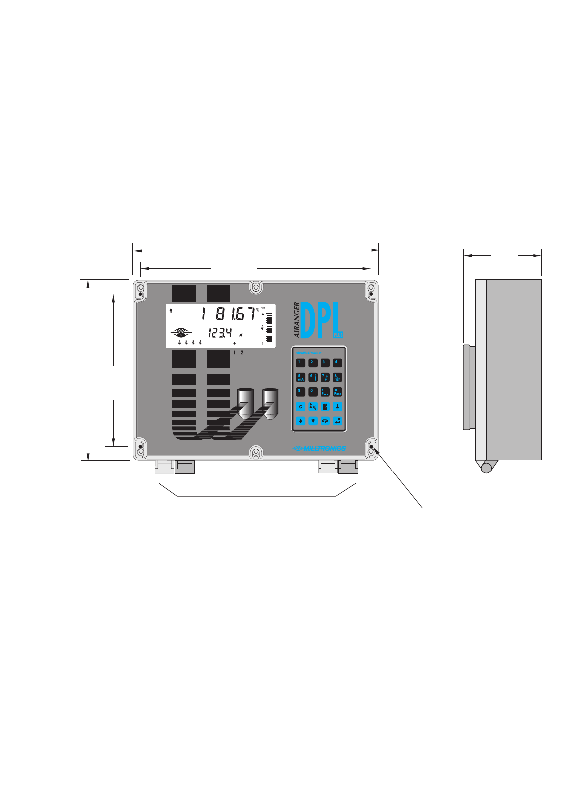
ENCLOSURE: Chemical resistant, light weight, dust tight, liquid tight, easy to work with.
LCD: Large digits for Reading and programming value displays.
Custom Graphic Symbols for continuous indication of operating conditions.
PROGRAMMER: 20 tactile feedback keys for easy access to programming and operating functions.
Magnetic mounting and infrared interface permit removal on programming completion.
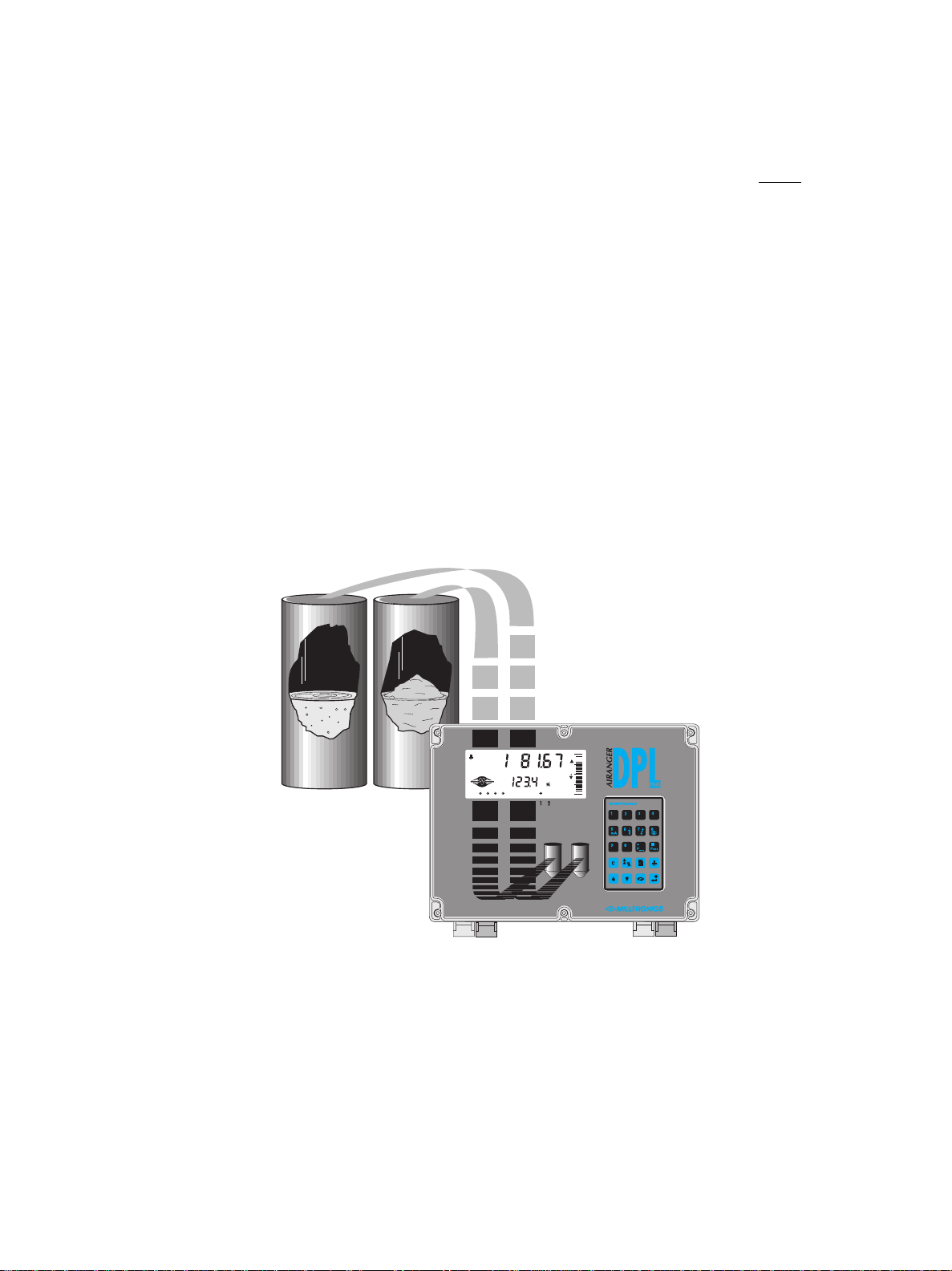
SCANNING: Substantially reduces equipment costs for an additional vessel (present or future).
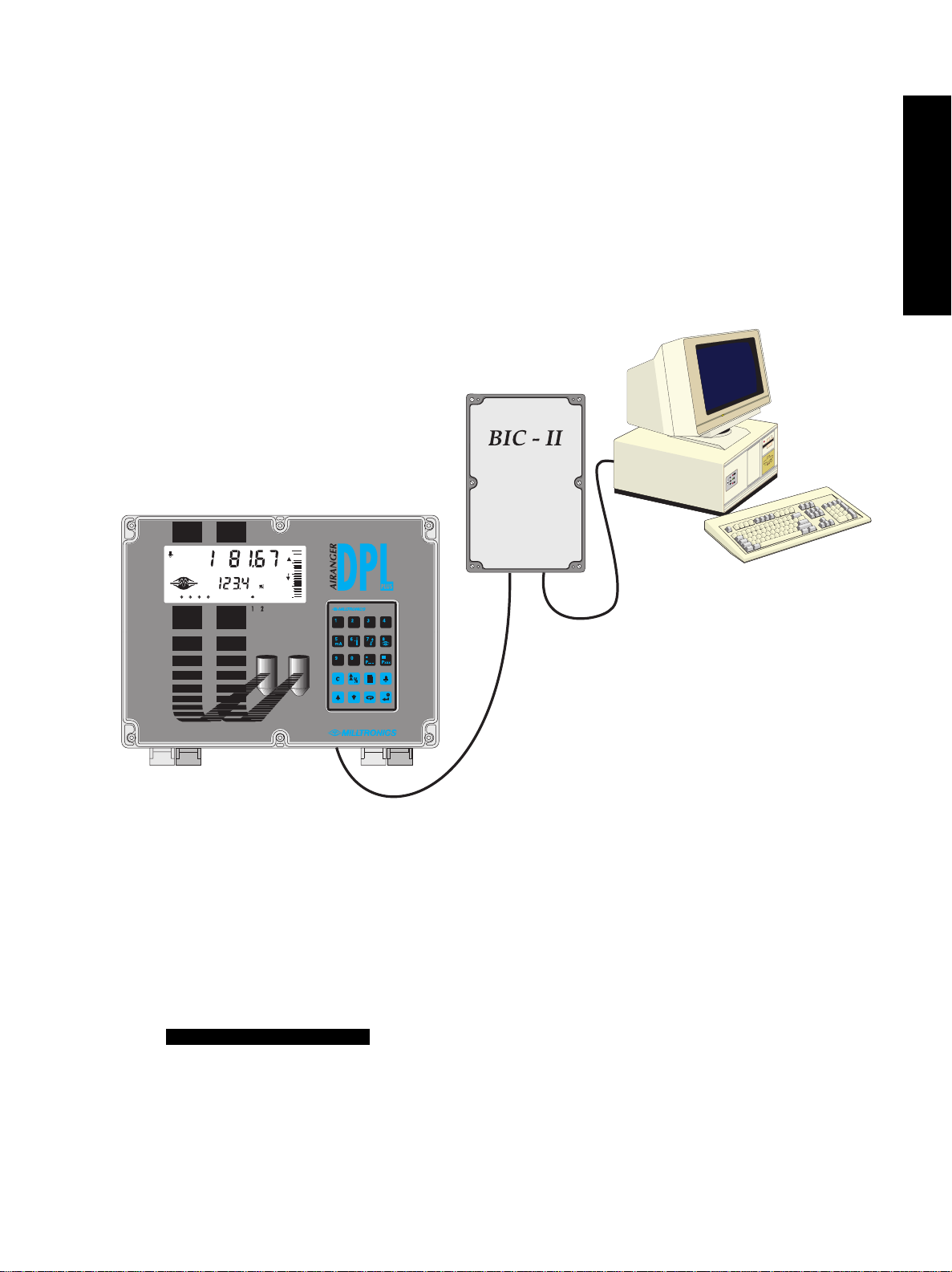
COMMUNICATIONS: Simplex transmission of measurement and operating condition data.
Compatible with the Milltronics BIC-II for buffered conversion to RS-232C or RS-422.
SPEED: Fast 16/32 bit microprocessor at 16.7 MHz clock speed.
1 vessel (point) per second scanning speed capability.
RELIABILITY: Surface Mount Technology (SMT), also provides for full features in a compact design.
Sonic IntelligenceTM ensures all measurements are accurate and reliable.
Immune to power interruptions. All programming is stored indefinitely. Dynamic
operating data is retained for one hour and updated immediately on power resumption.
PROGRAMMABLE FEATURES
Typically, a very small percentage of the programmable features require operator alteration. However, for
demanding measurement requirements any operator programmable feature may be adjusted as desired.
Following is a list of some of the features that make the DPL+ easy to program, yet versatile enough to
handle complex level measurement requirements.
GENERAL FEATURES
DIRECT ACCESS: Any operator programmable feature may be accessed directly.
SCROLL ACCESS: Single button "scroll forward", single button "scroll back", to key features.
OPERATION: Select "level","space","distance","difference","average", or "tripper" operation.
MATERIAL: Liquid or Solid; automatically adjusts echo processing with one entry.
RESPONSE: Slow, medium, fast, surge, or turbo response to material level changes, one entry.
UNITS: Display Readings in m, cm, mm, ft, in, %, or any other units desired.
ADDITIONAL FEATURES (use as desired)
VOLUME: 8 pre-programmed tank shape options
2 universal tank shape programming methods
FAILSAFE: Numerous failsafe options for process control equipment activation.
RELAYS: 8 functions including level, rate of change, pump control, temperature and more
Fixed or independent on/off setpoints
mA OUTPUTS: Based on level, space, distance, volume, difference, or average.
4 range selections, 0-20, 4-20, 20-0, or 20-4 mA
Adjustable range and over-range limits
PL-508 8

INSTALLATION
Installation shall only be performed by qualified personnel,
and in accordance with local governing regulations.
The following procedure applies to all DPL+ level monitor installations. See
Application Examples for additional installation requirements. Also, refer to the instruction manuals of all other
equipment connected to the DPL+ for additional installation instructions.
AIRANGER DPL PLUS
Installation should only be performed by qualified personnel, and in accordance with all governing regulations.
LOCATION
Inspect all potential mounting locations. Choose a location suited to the DPL+ polycarbonate enclosure and
the following location recommendations.
The ideal DPL+ mounting location is where the:
1. Ambient temperature is always within -20 to 50 °C (-5 to 122 °F).
2. DPL+ front cover has sufficient room to swing open.
3. Operator and electronics are not exposed to the weather.
4. Cable length requirements are minimal.
5. Mounting surface is free from vibration.
Avoid mounting locations where the DPL+ is:
» exposed to direct sunlight. (Otherwise, provide a sun shield.)
» close to high voltage or current runs, contactors, or SCR control drives.
CABLE/CONDUIT ENTRY REQUIREMENTS
Determine the number of enclosure cable/conduit entries required for:
» Transducers
» TS-3 temperature sensors (if used)
» BIC-II (if used)
» mA outputs (if used)
» Relays (if used)
» Synchronization (see Interconnection\Level System Synchronization)
» Power
Transducer cables must be run in a grounded metal conduit, separate from
other wiring, (except TS-3 temperature sensor wiring, if applicable).
TECHNICAL REFERENCE
INSTALLATION
PL-508 9

MOUNTING This product is susceptable to electrostatic shock.
Follow proper grounding procedures.
Inspect all cartons and packaging for possible damage during shipment, before removing the DPL+ and
associated equipment.
1. Loosen the 6 enclosure lid (captivated) screws and swing the lid open.
2. Remove the 4 Board B mounting screws (outer corners) and remove the circuit board assembly.
3. Drill sufficient holes in the enclosure bottom to meet enclosure cable/conduit entry requirements.
4. Attach the enclosure to the selected mounting surface. (4 predrilled screw holes provided.)
5. Attach the conduits/cable hubs to the enclosure. (Do not apply undue force.)
6. Reinstall the circuit board assembly.
Non metallic enclosure does not provide grounding between connections.
Use grounding type bushings and jumpers.
Transducer Mounting
Objects near the transducer face cannot be reliably detected. Mount the transducer above the highest
material level (away from the nearest monitored object) by the following
Nearest Distance
.
NEAREST DISTANCE TRANSDUCER TYPES
0.33 m (1.08 ft) ST-H, ST-25, XCT-8, XPS-10, XCT-12, XPS-15, ST-50
0.66 m (2.17 ft) XPS-30, XPS-40
0.99 m (3.25 ft) ST-100, LR-21, XLT-30, XLS-30
1.32 m (4.33 ft) LR-13, XLT-60, XLS-60
106 mm
(4.2")
267 mm
(10.5")
209 mm
(8.2")
Suitable location for conduit entrances.
Use water tight conduit hubs to maintain the enclosure rating.
285 mm
(11.2")
172 mm
(6.8")
mounting hole 4.3 mm (0.17") diameter
access under lid (4 places)
PL-508 10

INTERCONNECTION
Before interconnecting system components to the DPL+ terminals, verify all components have been installed
in accordance with the associated product instruction manuals.
Connect all associated equipment cable shields to the DPL+ shield connections. To avoid differential ground
potentials, do not connect cable shields to ground (earth) elsewhere. Insulate (tape) cable shields at all shield
junctions to prevent ground loops.
SW1 "Power"
selection
(AC Only)
Eprom
SW 2
"Tripper/
NORM"
scope
connections terminal
block
display
board A
Isolators
(optional)
board B
Relay contact terminals are for use with equipment
having no accessible live parts and wiring having
insulation suitable for at least 250 V.
The maximum allowable working voltage between
adjacent relay contacts shall be 250 V.
Power connections for dc operation.
Hazardous voltage present on transducer terminals during operation.
dc terminals shall be supplied from an SELV source in
accordance with IEC 1010-1 Annex H.
All field wiring must have insulation suitable for at least 250 V.
INSTALLATION
PL-508 11

SYSTEM DIAGRAM
Maximum system capability. Not all components or their maximum quantity may be required.
TRANSDUCER
Transducer cables must be run in a grounded metal conduit separate from
other wiring (except TS-3 temperature sensor wiring, if applicable).
TEMPERATURE SENSOR
Use TS-3 temperature sensors only. Don’t jumper the terminals if TS-3’s are not used.
to transducers
Belden 8760 (or equivalent)
18 AWG, 2 wire, shielded / twisted
to TS-3 (s)
AiRanger
DPL Plus Milltronics transducer, see Specifications
Milltronics TS-3, temperature sensor
customer device
customer alarm, pump or control device
Milltronics BIC-2, buffered interface converter
communication loop
relay output
mA output
Hazardous voltage present
on transducer terminals
during operation.
PL-508 12

RELAYS
Relays are shown in de-energized state.
mA OUTPUTS GROUNDED COMMON
FLOATING COMMON
See for ratings.
to customer’s equipment maximum loading 350 Ω
mA output into floating input ONLY. 750 Ωmax.
Ground cable shield at other end
01/25/99
to customer’s equipment
All relays are certified for use in equipment
where the short circuit capacity of the
circuits in which they are connected is
limited by fuses having ratings not
exceeding the rating of the relays.
SPECIFICATIONS
INSTALLATION
PL-508 13

ISOLATED OUTPUTS (optional)
LIs-1 isolators are factory installed when ordered with the DPL+. If an isolator kit is installed on site, refer to
the LIs-1 Isolator instruction bulletin for additional installation details.
BIC-II
Connect the Milltronics BIC-II (if required) to the Peripheral Communications terminals as follows.
Refer to PL-371 for specific
BIC-II terminal connections.
To RS-232C or
RS-422 host device.
Max run 15 m (50 ft).
Beldon 8760 (or
equivalent) 18 AWG, 2
wire, shielded/ twisted.
Max run 1500 m (5000 ft).
Ground shield at one end only. Recommend
grounding at LIs-1 mounting screw.
isolated 4-20 mA output
wiring into 600 Ωmax.
Route output wiring cable in
separate conduit, entering
enclosure as near as
possible to isolator.
Keep wiring as short as
possible. Do not route cable
along terminal board.
PL-508 14

LEVEL SYSTEM SYNCHRONIZATION
Avoid mounting the DPL+ near another ultrasonic level monitor. Likewise, when more than one monitor is
installed within a single plant/facility, ensure the transducer cables of each system are run in separate
grounded metal conduits. If this system separation is impractical, or despite separation efforts measurement
difficulties are encountered, system synchronization may be required.
To synchronize the DPL+ with an AIRANGER XPL Plus or another DPL+...
1. Mount the level monitors together in one cabinet.
2. Ensure the level monitors share a common power (mains) supply, and ground (earth).
3. Interconnect the SYNC terminals of the level monitors to be synchronized.
To synchronize the DPL+ with other Milltronics ultrasonic
level monitors (not listed) contact Milltronics
or your local distributor.
INSTALLATION
PL-508 15

POWER
Before making the power connection, ensure proper voltage selection.
AC Supply Wiring
The equipment must be protected by a 15 A fuse or
circuit breaker in the building installation.
A circuit breaker or switch in the building installation, marked as the disconnect switch,
shall be in close proximity to the equipment and within easy reach of the operator.
DC Supply Wiring ( 24 V )
Never operate the DPL+ with the enclosure lid open, or with the
ground (earth) wire disconnected.
Ensure that any associated alarm or control equipment is
disconnected until satisfactory operation is verified.
SW 1 switch shown in the
‘OFF’ position.
Select appropriate voltage. 100 / 115 / 200 / 230 V
50 / 60 Hz
select voltage via SW 1
18 to 30 V dc
PL-508 16

INSTALLATION
PL-508 17

PL-508 18

PROGRAMMING
Operator programmable features are identified by a Point Number and Parameter Number. The Point Number
refers to the Transducer (vessel) Number, Relay Number, mA Output Number, or TS-3 Number
as identified by the Point Type indicators. Parameter Numbers have a preset Parameter Value for each
Point Number.
Programming is accomplished by altering the preset Parameter Values as required to obtain the RUN mode
operation desired. All operator programmable features are defined in the Quick Start Parameters, Application
Parameters, and Enhancement Parameters sections of this instruction manual.
DISPLAY
In the program mode, the Point Type, Point Number, Parameter Number, and Parameter Value (as well as a
variety of other programming information) may be viewed.
Note that many indicators are specific to certain programming conditions and therefore,all indicators are not
displayed at any given time.
Parameter Number the programmable feature the Parameter Value pertains to.
Point Type the Point Number refers to a Transducer, Relay, mA Output, or TS-3.
Point Number the Transducer, Relay, mA Output or TS-3 # the Parameter Value pertains to.
Parameter Value the current value of the Parameter Number for the Point Number displayed.
Percent indicates the Parameter Value is displayed in percent.
Invalid Entry indicates the value entered is questionable (are you sure?).
Auxiliary Function indicates Auxiliary Function access (applies to only some Parameter Numbers).
Scroll Access Tag indicates the Parameter Value may be scroll accessed.
Program Mode indicates the program mode is accessed.
Parameter
Value
Point Number
Point Type
Units
Invalid
Entry
Auxiliary
Function
Scroll
Access
Tag
Parameter
Number
Program
Mode
Transducer
Relay
Analog Output
TS-3
Index
Relay in
Service
PROGRAMMING
PL-508 19

KEYPAD
In the program mode, use the DPL+ programmer keys to perform the identified functions.
shift access to Point Number, Parameter Number, or Parameter Value display.
– input the numeric value into the accessed display.
input a Parameter Value decimal point (moves Profile and TVT Pointers left).
input a negative Parameter Value (moves Profile and TVT Pointers right).
delete the current Parameter Value display (initiate a parameter reset).
store the current Parameter Value in memory (complete a parameter reset).
switch the Parameter Value to % or Units (access Auxiliary Parameter Function).
increase the accessed display value.
decrease the accessed display value.
take an ultrasonic measurement.
enter the RUN mode.
%
Numeric Value Keys
Function Keys
C
%
PXXX
P
0
9
PL-508 20
Other manuals for AIRANGER DPL PLUS
1
Table of contents
Other Milltronics Industrial Equipment manuals
Popular Industrial Equipment manuals by other brands

Siemens
Siemens SIRIUS 3RA1923-1B operating instructions

Pepperl+Fuchs
Pepperl+Fuchs Absolute Rotary Encoder manual

Stoll
Stoll GLOBAL Operating and maintenance manual

R.V.R. Elettronica
R.V.R. Elettronica SDC100 user manual

Racing
Racing MC S6 Series instruction manual

YZ Systems
YZ Systems DynaPak 3010RNM Series Support manual