LACROIX City MILLENIUM User manual

Updated: 06/01/2021
MILLENIUM / SMART MILLENIUM
USER MANUAL

USER MANUAL
2
FR
CONTENTS
1. PREAMBLE.......................................................................................................................................................................................................... 3
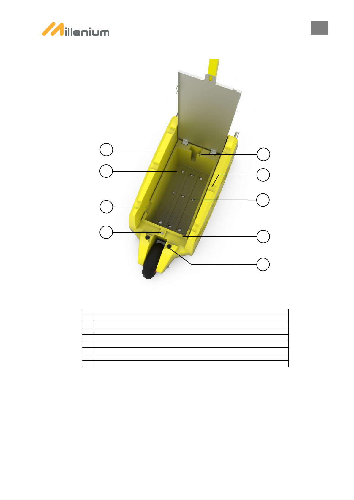
2. OVERVIEW........................................................................................................................................................................................................... 4
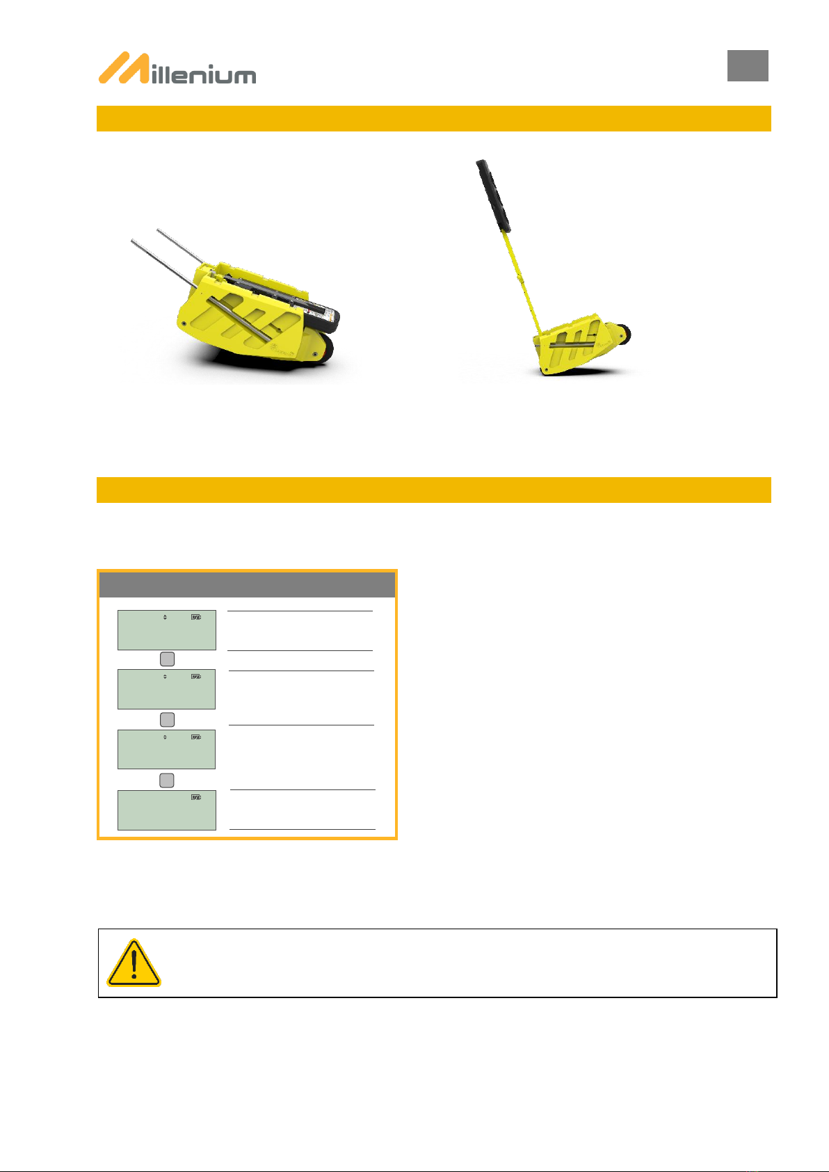
3. PREPARATION FOR DEPLOYMENT................................................................................................................................................................. 6
4. MOVING THE LIGHT ........................................................................................................................................................................................... 7
5. INITIAL ACTIVATION OF LIGHTS ...................................................................................................................................................................... 7
6. PAIRING ............................................................................................................................................................................................................... 8
A. Pairing Procedure ...................................................................................................................................................................................... 9
B. Procedure for Adding a PTL to an Existing System:................................................................................................................................ 10
C. Procedure for Removing a PTL from an Existing System: ...................................................................................................................... 10
7. PROGRAMMING THE PTLS ............................................................................................................................................................................. 10
A. Standard Mode: ....................................................................................................................................................................................... 11
B. Standard Mode + Worksite Exit ............................................................................................................................................................... 12
C. Manual Alternating Mode: ........................................................................................................................................................................ 13
D. Flashing Yellow Mode:............................................................................................................................................................................. 13
E. Manual Mode: .......................................................................................................................................................................................... 14
F. Vehicule actuated Mode: ......................................................................................................................................................................... 15
G. Green on Detection Mode:....................................................................................................................................................................... 16
H. Plant crossing Function:........................................................................................................................................................................... 17
8. CYCLE IN PROGRESS...................................................................................................................................................................................... 17
9. PARAMETERS MENU ....................................................................................................................................................................................... 18
A. Language: ................................................................................................................................................................................................ 18
B. Remote Control Settings:......................................................................................................................................................................... 18
C. PTL Settings:............................................................................................................................................................................................ 18
D. Information: .............................................................................................................................................................................................. 18
E. Maintenance:............................................................................................................................................................................................ 18
F. Reset:....................................................................................................................................................................................................... 18
10. SMART MILLENIUM MENU .............................................................................................................................................................................. 19
11. PTL SHUTDOWN / STANDBY .......................................................................................................................................................................... 19
12. REMOTE CONTROL.......................................................................................................................................................................................... 20
A. Activation.................................................................................................................................................................................................. 20
B. Standby:................................................................................................................................................................................................... 20
C. Remote Control SCREEN:....................................................................................................................................................................... 20
D. Switch Off Remote Control: ..................................................................................................................................................................... 20
E. Audible Alarms:........................................................................................................................................................................................ 20
F. Power Supply:.......................................................................................................................................................................................... 21
G. Adding a Remote Control to a PTL System:............................................................................................................................................ 21
H. System Reset:.......................................................................................................................................................................................... 21
13. RADIO ................................................................................................................................................................................................................ 21
14. RADAR............................................................................................................................................................................................................... 22
15. AVAILABLE OPTIONS ...................................................................................................................................................................................... 22
A. FLASHING BEACON:.............................................................................................................................................................................. 22
B. Anti-Theft Bar:.......................................................................................................................................................................................... 22
C. External Countdown Timer: ..................................................................................................................................................................... 23
D. Anti-Theft Cage:....................................................................................................................................................................................... 23
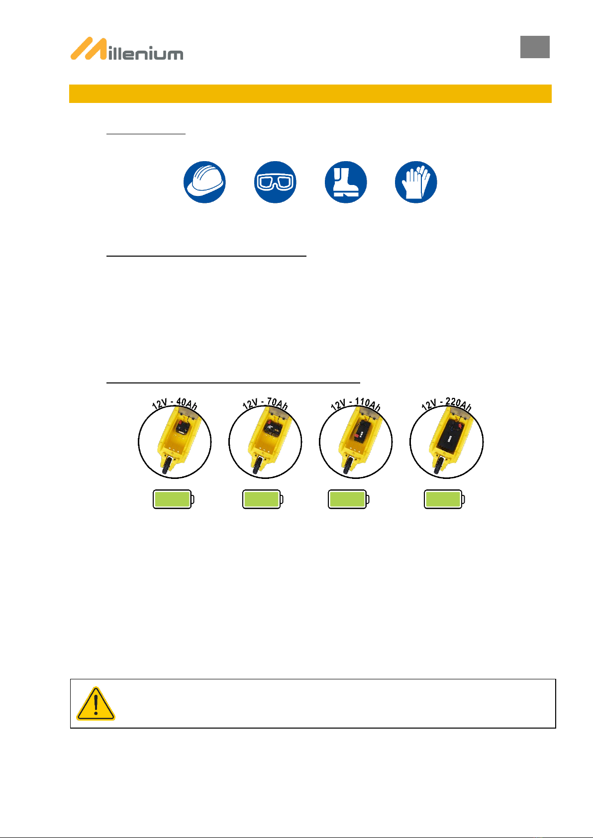
16. BATTERY........................................................................................................................................................................................................... 23
17. TRANSPORTATION .......................................................................................................................................................................................... 24
18. CLEANING AND MAINTENANCE..................................................................................................................................................................... 24
19. STANDARDS / SAFETY .................................................................................................................................................................................... 24
20. CONTACT TECHNICAL SUPPORT.................................................................................................................................................................. 24

USER MANUAL
3
FR
Preamble
1. PREAMBLE
A. PRECAUTIONS
Before handling the product or its accessories, the use of the PPE mentioned below is mandatory:
Before using the device, please read this operating manual fully and keep it for future use.
B. MAKING THE LIGHTS OPERATIONAL:
Millenium and Smart Millenium traffic lights are all IDENTICAL and INDEPENDENT; there are no master or slave lights.
Power up each light by connecting them to a 12 V battery or two 6 V batteries in series observing the correct polarity or
on 230 V (contact your dealer). To switch on the remote control, press one of its buttons.
The lights are switched on, paired and programmed from the remote control.
C. BATTERY COMPATIBILITY AND BATTERY LIFE:
* Varies according the cycle used, the ambient light, humidity, temperature and the programming mode used. As measurementtechnology
and instruments are constantly evolving, this information is provided for general reference only.
If the battery level is low, alerts are reported to the remote control allowing the user to replace it before the lights go out
(Battery < 24 hrs / Battery < 12 hrs / Battery 1 hr).
When there is less than 24 hours’ battery life, the traffic lights automatically switch to STANDARD mode.
If the battery life is less than or equal to 1 hour, the traffic lights switch to autonomy mode, equating to the lights going out,
the programming is then retained for 20 minutes, allowing the lights to quickly be returned to operational status after the
battery is changed. Beyond this 20-minute period, the pairing is retained, and the lights need to be programmed.
3 days*
8.5 days*
15 days*
35 days*
AFTER SWITCHING TO AUTONOMY MODE, THE PROGRAMMING OF THE PTLs IS PRESERVED FOR 20 MINUTES

USER MANUAL
4
FR
2. OVERVIEW
1
LIGHT-HEAD
11
ACCESS PANEL
2
RED LENS
12
FLASHSING BEACON SLOT (OPTIONAL)
3
YELLOW LENS / INTERNAL COUNTDOWN TIMER
13
STORAGE SPACE FOR REMOTE CONTROL NO. 1
4
GREEN LENS
14
UPPER EXTENSION LOCKING HANDLE
5
UPPER EXTENSION
15
LOWER EXTENSION LOCKING HANDLE
6
LOWER EXTENSION
16
RETRACTABLE LIFTING ARMS
7
TIGHTENING LEVER
17
PUNCTURE-PROOF REAR WHEELS
8
CHASSIS
9
BATTERY COVER
10
PUNCTURE-PROOF FRONT WHEEL
1
5
15
8
10
9
7
4
3
2
11
14
16
17
13
12
6

USER MANUAL
5
FR
1
STORAGE SPACE FOR REMOTE CONTROL NO. 2
2
BATTERY STRAP PASS-THROUGH / GROUND ANCHORING PASS-THROUGH FOR LIGHT
3
ANTI-THEFT BAR PASS-THROUGH (BAR OPTIONAL)
4
PADLOCK PASS-THROUGH (PADLOCK OPTIONAL)
5
POWER CABLE PASS-THROUGH
6
TRAFFIC LIGHT STACKING PASS-THROUGH
7
GROUND ANCHORING PASS-THROUGH FOR LIGHT
8
230 V POWER CABLE PASS-THROUGH FOR BATTERY CHARGING
9
LIGHT-HEAD GUARD
5
1
2
7
4
3
8
9
6

USER MANUAL
6
FR
3. PREPARATION FOR DEPLOYMENT
A. UNFOLDING THE LIGHT-HEAD:
B. FOLDING THE LIGHT-HEAD:
C. DEPLOYMENT OF TELESCOPIC EXTENSIONS:
1) Loosen the handle half a turn
2) Pull to release the locking bolt
3) Fold or unfold the extension
4) Tighten the handle
Perform this step on both handles
D. LOCKING/UNLOCKING THE HEAD FOLDING SYSTEM:
Once the extensions have been deployed, lock the tightening lever to ensure optimum stability for the light-head and
extensions.
Note: before folding the light-head over the box, ensure that the tightening lever is in the unlocked position.

USER MANUAL
7
FR
4. MOVING THE LIGHT
Wheelbarrow Mode
Trolley Mode
5. INITIAL ACTIVATION OF LIGHTS
The activation procedure allows users to select a country and the language for using Millenium traffic lights.
As activation is stored in the remote control’s memory, this step is only required for first use or after a system reset.
A
QUICK START
OK
QUICK START
SELECT COUNTRY
FRANCE
SELECT LANGUAGE
FRENCH
FINISHED
OK
OK
Position the remote control opposite the
infrared signal window located on the
back of the light-head.
Select the QUICK START menu from the
remote control.
As the choice of country affects the
programming mode of your traffic lights,
please ensure you comply with the
country where it is used.
DUE TO SPECIFIC LOCAL REGULATORY REQUIREMENTS, THE SELECTED COUNTRY MUST BE IDENTICAL TO
THE COUNTRY WHERE THE PTLs ARE USED.

USER MANUAL
8
FR
6. PAIRING
The lights and the remote control are equipped with radios that enable them to communicate to provide enhanced worksite
safety. The radio, which is embedded in the remote control, allows it to communicate remotely with the lights deployed,
monitor them and receive remote alerts.
The pairing phase makes it possible to group individual lights and the remote control together into a unit called a “system”.
A system can contain a maximum of 4 lights and 3 remote controls.
Lights are paired using infrared, the infrared signal window is located on the back of each light-head. The remote control
should be positioned a few centimetres away and opposite the infrared signal window.
During pairing, the ID of each light is indicated on the central lens for simplified deployment:
ENSURE THAT THE LIGHTS TO BE PAIRED ARE POWERED BEFORE BEGINNING THE PAIRING PHASE.
IF THE REMOTE CONTROL GOES INTO STANDBY MODE BEFORE PAIRING IS COMPLETE, THE PAIRING IS LOST.
ENSURE THE REMOTE CONTROL IS KEPT ACTIVE DURING THE PROCESS BY PRESSING THE BUTTONS ON THE LEFT
OR RIGHT. THE STANDBY TIME (1 MIN BY DEFAULT) CAN BE CHANGED FROM THE PARAMETERS MENU, REMOTE
CONTROL SETTINGS.

USER MANUAL
9
FR
A. PAIRING PROCEDURE
ENSURE THAT THE PTL TO BE PAIRED ARE POWERED BEFORE BEGINNING THE PAIRING PHASE.
WHEN THE PTL ARE SWITCHED OFF BY DISCONNECTING THE BATTERIES, THE PAIRING IS SAVED BY THE
LIGHTS SYSTEM. THERE IS NO NEED TO REPEAT THIS STEP ON THE NEXT TIME DEPLOYMENT IF THE SYSTEM
COMPRISES THE SAME LIGHTS AND THE SAME REMOTE CONTROL.
IF THE REMOTE CONTROL GOES INTO STANDBY MODE BEFORE PAIRING IS FINISHED, THE PAIRING IS LOST.
ENSURE THE REMOTE CONTROL IS KEPT ACTIVE DURING THE PROCESS BY PRESSING THE BUTTONS ON THE LEFT
OR RIGHT. THE STANDBY TIME (1 MIN BY DEFAULT) CAN BE CHANGED FROM THE PARAMETERS MENU, REMOTE
CONTROL SETTINGS.
PAIRING 3/4 PTLs
OK
PAIRING
SCAN PTL A
OK
PTL A OK
SCAN PTL B
OK
PTL B OK
OK
OK
OK
NEXT PTL
OK
:
PAIRING 2 PTLs
OK
PAIRING
SCAN PTL A
OK
PTL A OK
SCAN PTL B
OK
PTL B OK
OK
OK
OK
FINISHED
OK
SCAN PTL C
OK
PTL C OK
OK
OK
FINISHED
OK
PAIRING FINISHED
OK
Available choices:
FINISH OR NEXT PTL
Next PTL: when there are 4 PTL to pair.
PAIRING FINISHED
OK
Position the remote control opposite the
infrared signal window located on the
back of the light-head.
Position the remote control opposite the
infrared signal window located on the
back of the light-head.
Position the remote control opposite the
infrared signal window located on the
back of the light-head.
Position the remote control opposite the
infrared signal window located on the
back of the light-head.
Position the remote control opposite the
infrared signal window located on the
back of the light-head.
Select the PAIRING menu from the
remote control.
Select OK to complete pairing.

USER MANUAL
10
FR
B. PROCEDURE FOR ADDING A PTL TO AN EXISTING SYSTEM:
Adding a light to an existing system makes it possible to switch from a 2-light system to a 3- or 4-light system.
The ADD LIGHT function is available from the PARAMETERS menu.
ADDING A PTL WHEN THERE IS A CYCLE IN PROGRESS INTERRUPTS THE CYCLE AND CAUSES THE PTLs TO
CHANGE TO RED.
C. PROCEDURE FOR REMOVING A PTL FROM AN EXISTING SYSTEM:
To remove or replace a PTL, a new pairing is required.
Refer to the PAIRING chapter for more information.
7. PROGRAMMING THE PTLs
Once the PTLs have been PAIRED, the PROGRAMMING menu appears. This menu gives you a choice of 7
programmable modes for your PTLs:
The following modes are available on MILLENIUM :
- STANDARD MODE
- STANDARD + WORKSITE EXIT MODE (3 paired PTLs minimum)
- MANUAL ALTERNATING MODE (2 paired PTLs maximum)
- FLASHING YELLOW MODE
- MANUAL MODE
SMART MILLENIUM –Traffic Regulation traffic feature 2 additional modes:
- VEHICULE ACTUATED MODE
- GREEN ON DETECTION
ADDING A PTL
OK
PARAMETERS
PTL SETTINGS
ADD PTL
SCAN PTL X
PTL X OK
OK
OK
OK
Position the remote control opposite the
infrared signal window located on the
back of the light-head.

USER MANUAL
11
FR
A. STANDARD MODE:
Classic mode allows you to set up 2, 3 or 4 PTLs.
CYCLES BEGIN AFTER ALL RED ALLOWING THE CENTRAL AREA TO BE FULLY CLEARED.
2 PTL SYSTEM
NR. VEHIC / DAY
LESS THAN 2,000
SELECT DISTANCE
100m
PROGRAMME MODE
FINISHED
OK
OK
Available choices:
< 2,000 / 2 to 5,000 / 5 to 8,000 / 8 to
11,000
Available choices:
20 m to 2000 m
3 OR 4 PTL SYSTEM
Available choices:
< 2,000 / 2 to 5,000 / 5 to 8,000 / 8 to
11,000
Available choices:
20 m to 2000 m
JUNCTION TYPE
CROSSED
NR. VEHIC / DAY
LESS THAN 2,000
SELECT DISTANCE
100m
PROGRAMME
MODE FINISHED
OK
OK
OK
Available choices:
Crossed / Rotating

USER MANUAL
12
FR
B. STANDARD MODE + WORKSITE EXIT
This mode is intended for use on worksites where the work area is equipped with a set of PTLs to allow vehicles to safely
exit the work area. On an All Red request (see All Red overview below) from the remote control, the PTLs change to yellow
then red, and the worksite PTL change to green. Due to the presence of a minimum of 1 PTL on the worksite, this mode
is only available when 3 or 4 PTLs are paired.
MODE AVAILABLE IF ALL PAIRED PTLs ARE LOCATED AT A MAXIMUM DISTANCE OF 800 M.
POSSIBILITY TO ACTIVATE PLANT CROSSING AUTOMATICALLY VIA THE RADAR EVEN IF ALL PTLs ARE NOT FITTED
WITH IT. MAKE SURE THAT PTLs WITH RADARS ARE POSITIONED ON THE WORKSITE EXIT ROAD(S). THE ID FOR
WORKSITE EXIT PTLs MUST BE B OR D.
PLANT CROSSING CAN BE MANUALLY OR AUTOMATICALY DEACTIVATED.
AUTOMATIC DEACTIVATION TIMING DEPENDS IF PTL ON WORKSITE EXIT IS EQUIPPED WITH REGULATION RADAR OR NOT.
►MILLENIUM (NO RADAR) : PLANT CROSSING DURATION = ALL RED TIMING
►SMART MILLENIUM (WITH RADAR) : PLANT CROSSING ENDING AFTER 8SEC OF NON DETECTION OR AFTER 30SEC
CYCLES BEGIN AFTER ALL RED ALLOWING THE CENTRAL AREA TO BE FULLY CLEARED.
2 TRAFFIC PTLs
Available choices:
Nbr of site exits: 1 or 2
Varies based on the number of PTLs paired
Available choices:
Worksite light: Light B or B & D
Varies based on the number of PTLs paired
Available choices:
Manual or automatic activation
Automatic: only available on Smart Millenium
OK
NR. PTL
TRAFFIC: 2
PTL
SYNCHRONISED
WORKSITE EXITS:
1 PTL
WORKSITE PTL:
PTL B
PLANT CROSSING
MANUAL ACTIV.
OK
OK
OK
PROGRAMME MODE
FINISHED
OK
3 TRAFFIC PTLs
Available choices:
< 2,000 / 2 to 5,000 / 5 to 8,000 / 8 to 11,000 /
11 to 14,000
Available choices:
20 m to 2000 m
OK
NR. PTL
TRAFFIC: 3
JUNCTION TYPE
CROSSED
NR. VEHIC / DAY
LESS THAN 2,000
SELECT DISTANCE
100m
OK
OK
WORKSITE EXITS:
1 PTL
OK
Available choices:
Crossed ou Rotating
Available choices:
Nbr of site exits: 1 or 2
Varies based on the number of PTLs paired
WORKSITE PTL
PTL B
PLANT CROSSING
MANUAL ACTIV.
OK
OK
PLANT CROSSING
MANUAL DEACT.
OK
Available choices:
Worksite light: Light B or B & D
Varies based on the number of PTLs paired
Available choices:
Manual or Automatic deactivation
Automatic: only available on Smart Millenium
PROGRAMME MODE
FINISHED
OK
Available choices:
Manual or Automatic deactivation
Automatic deactivation timing :
MILLENIUM : plant crossing ending after ALL RED timing
SMART MILLENIUM : plant crossing ending after 8s of non-
detection on or after 30 seconds
Available choices:
Manual or Automatic deactivation
Automatic deactivation timing :
MILLENIUM : plant crossing ending after ALL RED timing
SMART MILLENIUM : plant crossing ending after 8s of non-
detection or after 30 seconds
PLANT CROSSING
MANUAL DEACT.
OK
Available choices:
Synchronised or Crossed

USER MANUAL
13
FR
C. MANUAL ALTERNATING MODE:
Mode suitable for worksites requiring dynamic alternating lanes. The user manually operates the alternating system by
giving the green light or red light from the remote control. As PTLs are interconnected by radio, giving the green light to
traffic from one direction means that the PTL for the other direction will automatically switch to red. An All Red phase can
also be simulated from the remote control.
Mode reserved for systems comprising 2 paired PTLs and worksites with perfect visibility of all traffic. To further enhance
safety when using this mode, LACROIX City recommends using flashing beacons, which are sold separately.
CYCLES BEGIN IMMEDIATELY FOLLOWING MODE SELECTION.
D. FLASHING YELLOW MODE:
This mode activates the flashing yellow on the central lens, mode used when the traffic no longer requires an alternating
traffic flow system to be implemented. The mode is also automatically activated on all currently operating system lights in
the following situations:
- Battery life < 12 hrs
- Battery disconnected from the PTL during use
- Radio fault (if modes Standard + Worksite Exit, Automatic Regulation, Green on Detection are active)
- Red lens fault (> 50% of the lens is faulty)
- PTL moved/fallen
Mode does not require any programming from the user.
CYCLES BEGIN IMMEDIATELY FOLLOWING MODE SELECTION.
REMOTE CONTROL INTERFACE
Automatic start-up of 2 red lights.
Select the carriageway to switch to green
using the UP or DOWN arrows, confirm
choice with OK.
Switch to red (recommended) before
carriageway B switches to green using
the UP or DOWN arrows, confirm choice
with OK.
The remote control now displays the
current system status.
MANUAL
ALTERNATING MODE
OK
IN PROGRESS
RED LIGHTS
ACTIVATE?
PTL A: GREEN
CURRENT
PTL A: GREEN
OK
ACTIVATE?
RED LIGHTS

USER MANUAL
14
FR
E. MANUAL MODE:
This mode allows the cycle duration to be manually adjusted.
MODE RESERVED FOR EXPERIENCED USERS.
CYCLES BEGIN AFTER ALL RED ALLOWING THE CENTRAL AREA TO BE FULLY CLEARED.
WHEN THE COUNTRIES BELGIUM, GERMANY, POLAND, CZECH REPUBLIC OR OTHER ARE SELECTED FROM THE
ACTIVATION MENU, THE DURATION FOR THE CENTRAL YELLOW IS REPLACED BY
THE DURATION OF THE CENTRAL YELLOW + RED.
REMOTE CONTROL INTERFACE
Distance adjustable from 20 to 2,000 m
using the UP and DOWN keys.
Green duration adjustable from 5 to 120 seconds
Pressing and holding the UP and DOWN keys allows the
user to increase or decrease the time in 10-second
increments.
OK
MANUAL MODE
CENTRAL YELLOW
5 SECS
SELECT DISTANCE
100m
GREEN DURATION
20 SECS
OK
OK
PROGRAMME MODE
FINISHED
OK
Adjusts the length of the central yellow
(5 secs = regulatory duration) using the
UP and DOWN keys.

USER MANUAL
15
FR
F. VEHICULE ACTUATED MODE:
Mode available on Smart Millenium –Traffic Regulation fitted with regulation radars.
Equipped with regulation radars built into each light-head, Smart Millenium - traffic regulation enable the optimised,
dynamic and automatic regulation of vehicle flows.
Once the cycles have begun, the regulation radars analyse the traffic and automatically adjust their cycles to the traffic.
The most-used road or roads will have a longer time on green than less-used roads.
By adjusting their cycles to how busy the location is where they are installed, Smart Millenium offer motorists reduced
waiting time. Site workers will also benefit from a better regulated and less stressful worksite.
VEHICULE ACTUACTED MODE ONLY AVAILABLE IF ALL PAIRED PTLs ARE EQUIPPED WITH REGULATION RADARS
AND LOCATED AT A MAXIMUM DISTANCE OF 800 M.
CYCLES BEGIN AFTER ALL RED ALLOWING THE CENTRAL AREA TO BE FULLY CLEARED.
REMOTE CONTROL INTERFACE
Available choices:
< 2,000 / 2 to 5,000 / 5 to 8,000 / 8 to
11,000 / 11 to 14,000
Available choices:
20 to 2,000 m
Pressing and holding the UP and DOWN keys allows
the user to quickly increase or decrease the distance in
increments.
VEHICULE
ACTUATED MODE
OK
JUNCTION TYPE
CROSSED
OK
SELECT DISTANCE
100m
OK
Available choices:
Crossed or Rotating
PROGRAMME MODE
FINISHED
OK
NR. VEHIC / DAY
LESS THAN 2,000

USER MANUAL
16
FR
G. GREEN ON DETECTION MODE:
Mode available on Smart Millenium –Traffic Regulation fitted with regulation radars.
Equipped with vehicle detection radars built into each light-head, Smart Millenium –Traffic Regulation traffic PTLs enable
the optimised, dynamic and automatic regulation of vehicle flows.
On red when no vehicle is detected, the PTLs automatically change to green when an approaching vehicle is detected.
This mode enables the dynamic adjustment of vehicle flows and keeps waiting time to a minimum.
When traffic flows are equivalent on the different roads, the system regulates traffic by dynamically optimising flows.
GREEN ON DETECTION MODE ONLY AVAILABLE IF ALL PAIRED PTLs ARE EQUIPPED WITH REGULATION RADARS
AND LOCATED AT A MAXIMUM DISTANCE OF 800 M.
CYCLES BEGIN AFTER ALL RED ALLOWING THE CENTRAL AREA TO BE FULLY CLEARED.
REMOTE CONTROL INTERFACE
Available choices:
< 2,000 / 2 to 5,000 / 5 to 8,000 / 8 to
11,000 / 11 to 14,000
Available choices:
20 to 2,000 m
Pressing and holding the UP and DOWN keys allows
the user to quickly increase or decrease the distance in
increments.
GREEN ON
DETECTION MODE
OK
JUNCTION TYPE
CROSSED
OK
SELECT DISTANCE
100m
OK
Available choices:
Crossed or Rotating
PROGRAMME MODE
FINISHED
OK
NR. VEHIC / DAY
LESS THAN 2,000

USER MANUAL
17
FR
H. PLANT CROSSING FUNCTION:
The plant crossing function involves interrupting current cycles on lanes reserved for traffic to allow worksite vehicles to
safely leave the area.
Plant crossing can be activated or deactivated in all modes once programming has been completed, except for MANUAL
ALTERNATING mode.
There are 2 possible worksite configurations:
- Worksite road(s) equipped with a PTL (see chapter STANDARD + WORKSITE EXIT)
- Worksite road(s) without a PTL
For worksite road(s) equipped with a PTL, select STANDARD + WORKSITE EXIT mode.
Activate PLANT CROSSING:
MILLENIUM:
- manually by pressing the STOP button on the remote control for 5 seconds
SMART MILLENIUM –Traffic Regulation: 2 possible choices (to be defined at the programming stage)
- manually by pressing the STOP button on the remote control for 5 seconds
- automatically when a vehicle is detected approaching the WORKSITE traffic lights (maximum distance between
PTLs : 800m)
Choice of automatic activation is only available in STANDARD + WORKSITE EXIT mode.
Deactivate PLANT CROSSING:
MILLENIUM: 2 possible choices (to be defined at the programming stage)
- manually by pressing the STOP button on the remote control for 5 seconds
- automatically after ALL RED defined based on programming (not available if PTLs are synchronised. Maximum
distance between PTLs : 800m)
SMART MILLENIUM –Traffic Regulation: 2 possible choices (to be defined at the programming stage)
- manually by pressing the STOP button on the remote control for 5 seconds
- automatically: Plant crossing is interrupted when there is no approaching vehicle detected for 8 seconds at the
worksite exit PTL; Plant crossing duration is limited to 30 seconds (maximum distance between PTLs : 800m).
Choice of automatic deactivation is only available in STANDARD + WORKSITE EXIT mode.
8. CYCLE IN PROGRESS
Once programming has been completed, the current programming can be viewed from the remote control. Pressing one
of the keys gives users access to CYCLE IN PROGRESS with details of the current programming.

USER MANUAL
18
FR
9. PARAMETERS MENU
The PARAMETERS menu is used to configure the following functions:
A. LANGUAGE:
Available languages: English/German/Spanish/Flemish/French/Italian/Polish/Portuguese/Czech
B. REMOTE CONTROL SETTINGS:
STANDBY REMOTE CONTROL: to adjust the screen timeout time
SCREEN BACKLIGHTING: to adjust the screen brightness
PROGRAMMING DELAY FOR SCAN: to set the maximum duration permitted to scan the different PTLs in an infrared
system
ADD REMOTE CONTROL: to add a remote control to a current system
C. PTL SETTINGS:
The PTL SETTINGS menu makes it possible to deactivate the following features:
ACCELEROMETER: the accelerometer detects PTL that have fallen or moved. Alerts are automatically reported to the
remote control 15 minutes after the end of a programming, enabling operators to deploy PTLs on the ground. 15 minutes
after programming, if a PTL has fallen or moved, the PTLs switch to safety mode; a MOVED PTL alarm is reported to the
remote control within 30 seconds. When a PTL is repositioned, the alarm is raised after 35 seconds, and the PTLs resume
their cycle after All Red.
RADIO: to create a system of PTLs and communicate between the PTLs and the remote.
RADAR: to automatically regulate traffic (only available on Smart Millenium –Traffic Regulation).
INTERNAL COUNTDOWN TIMER: can be deactivated when an external countdown time is used; the internal countdown
timer behaves like a classic orange light.
ADD PTL: to replace a damaged or faulty PTL or add a PTL to a paired system.
D. INFORMATION:
BATTERY CHARGE: estimated real-time battery charge level of system’s PTLs
HISTORY OF RECEIVED ALARMS: history of alerts or faults collated by the PTL system
PTL ID: to display the A, B, C, D ID of the PTL on the central lens
SERIAL NUMBER: to display the serial number of PTLs in a system
E. MAINTENANCE:
OPTICAL TEST: used to activate the different lenses to check how they are working (function not available when PTLs
are in operation)
F. RESET:
SYSTEM: resets the remote control
PASSWORD: resets the password allowing access to SMART MILLENIUM features

USER MANUAL
19
FR
10. SMART MILLENIUM MENU
Intended for those leasing, this menu is used to activate or deactivate SMART MILLENIUM functionality.
Menu only accessible when all paired PTLs are SMART MILLENIUM.
TO OBTAIN THE PASSWORD, CONTACT LACROIX CITY TECHNICAL SUPPORT (PRESENT PROOF OR PURCHASE).
11. PTL SHUTDOWN / STANDBY
A. SHUTDOWN PTLs:
There are 2 ways to shut down the PTLs:
1) From the SYSTEM SHUTDOWN menu →SYSTEM SHUTDOWN
2) By disconnecting the battery on each PTL (see procedure in the BATTERY section below)
Note: when the batteries are disconnected without going through the SYSTEM SHUTDOWN menu, the PTL pairing is
retained.
Note: the SYSTEM SHUTDOWN menu is equivalent to the end of a worksite and thus when shutting down paired PTLs,
the pairing is removed and will have to be performed again if the same system is redeployed.
Note: as a connected battery will discharge (even one that is not used), ensure that the battery cables are disconnected
after use.
B. PLACE PTLs ON STANDBY:
Placing the PTLs on standby allows the lenses to be switched off whilst retaining the current programming in the
background. When standby mode is deactivated, the lenses come back on and the PTLs resume their cycle.
Placing the PTLs on standby from the SYSTEM SHUTDOWN menu →PTL STANDBY
REMOTE CONTROL INTERFACE
PASSWORD
XXXX
OK
RADAR ACTIV.
Available choices:
Radar activated / Radar deactivated
To obtain the password, contact
LACROIX City technical support (present
proof or purchase).

USER MANUAL
20
FR
12. REMOTE CONTROL
A. ACTIVATION
The remote control can be activated by quickly pressing on any key.
B. STANDBY:
To optimise the remote control’s battery life, the device is configured by default to enter standby mode after 1 minute.
In order to preserve the remote control’s battery life, it is recommended to select the shortest time to enter standby mode.
The time to enter standby mode can be configured from the remote control’s PARAMETERS menu.
In standby mode, the remote control continues to communicate with the current traffic light system in order to collate alert
messages and inform the user.
C. REMOTE CONTROL SCREEN:
Symbol displayed when PTLs are paired on the remote control
Flashing symbol in case of a radio error
Symbol informing that an up/down choice is possible
Remote control charge
D. SWITCH OFF REMOTE CONTROL:
To ensure a continuous connection with the current PTL system, the remote control cannot be switched off; once the PTL
system has shut down, the remote control enters extended standby mode and stops communicating in order to conserve
its battery.
E. AUDIBLE ALARMS:
The remote control is fitted with an audible alarm to inform the user about an alert or a fault with the PTL system. After
sounding for 5 seconds, the alarm stops automatically. Configured by default, the audible alarm can be deactivated from
the remote control’s PARAMETERS menu.
INFRARED SENSOR
BACK
ACTIVATE/DEACTIVATE ALL RED
INTERFACE ARROW KEYS
(LEFT AND RIGHT ARROW KEYS INACTIVE)
ALERT/FAULT LED
ALL RED
ACTIVATION LED
PROGRAMME MODE
This manual suits for next models
1
Table of contents
Popular Industrial Equipment manuals by other brands

Parker
Parker OLAER IBV Series Repair instructions

York
York ZJ150 installation manual

Samoa
Samoa LARIUS PNEUMATIC HOIST 200 Operating and maintenance manual

morse
morse 195AM-A Operator's manual

Will Burt
Will Burt Hurry-Up Mast 3.5-7 Operator's manual

Endress+Hauser
Endress+Hauser Flexdip CYA112 operating instructions