EXCELSENSE SensorShield-1600 User manual

SensorShield-1600™
User Manual, V1.1

Table of Contents
Table of Contents 1
Overview 3
IMPORTANT SAFETY INSTRUCTIONS 4
Warning 4
Caution 5
Specifications 6
Mechanical Drawings 7
Ordering Options 8
Typical Installations 8
Sensor Mounting 10
Clear Glass Area Dimensions 11
Enclosure Mounting Instructions 12
Accessories 13
Triggering the SensorShield-1600™ 13
Manual Trigger 13
Manual Trigger using External Button 14
Automatic Trigger 15
Thermal Subsystem 15
SensorShield-1600 Thermal Subsystem 16
SensorShield-1600™ Modbus-RTU Interface 16
SensorShield-1600 Modbus Interface 17
Modbus-RTU Settings 19
Modbus Settings 19
Device ID Address 19
Modbus Data Addresses 19
Internal Modbus Server Update Rate 19
RS-232 Settings 19
Supported Function Codes 20
Data Memory Mapping 21
Holding Registers 21
Coils 23
Data Descriptions 24
Holding Register Data 24
DIDR - Device ID Register 24
SREG - System State Register 24
1

EREG - System Error Status Register 25
LCCH - Lifetime Cycle Count High Word Register 28
LCCL - Lifetime Cycle Count Low Word Register 28
LSCR - Lifetime Stall Count Register 29
CTOR - Cycle Timeout Register 29
TCIR - Timed Clean Interval Register 30
LCTR - Last Cycle Time Register 30
CCLR - Cycle Completion Level Register 30
MBTR - Main Board Temperature Register 31
WITR - Window Internal Temperature Register 31
DITR - Device Internal Temperature Register 31
Data Coils 32
PTPC - Power Type Coil 32
PLVC - Power Level Coil 32
RDYC - System Ready Coil 33
THSC - Thermal Heating Status Coil 33
TCEC - Timed Clean Enable Coil 34
LCSC - Last Cycle Status Coil 34
2

Overview
SensorShield-1600™ follows the same self-cleaning principles as the ToughEye-1700™ line of
cameras, providing industry-leading, zero maintenance, self-cleaning operation for
rear-mounted optical sensors and cameras, suitable for any industrial application where a clear
view is critical to the success of the operation.
It incorporates a rugged single-piece design, equipped with our field-proven and innovative
ClearSight™ technology. One can simply integrate this shield into a sensor enclosure by
replicating the indicated panel cutout and the hole pattern.
The SensorShield™ family of optical shields excels at three things: reliability,
zero-maintenance operation and clarity.
ExcelSense can customize SensorShield-1600™ installations for almost any application. Please
3

IMPORTANT SAFETY INSTRUCTIONS
Warning
1. This is an ITE class A device. In a domestic environment this product may cause radio
interference in which case the user may be required to take adequate measures.
2. All electrical connections must be made by qualified personnel in accordance with local
and national electrical codes and regulations. Electrical power is not to be applied to
conductors at any point during this process.
3. Connecting the SensorShield - 1600TM incorrectly poses a risk of injury due to electric
shock to the user, and can damage the device.
4. Damaged or faulty connections may leave electrical conductors bare and/or
short-circuited. Extra care must be taken during installation in order to avoid this
scenario. In such a circumstance, do not attempt to handle conductors before removing
power.
5. The SensorShield-1600™ viewing region is made with hardened glass. The user should
take necessary precautions when handling the system. If excessive, direct force is
induced, the glass may break, causing system failure and potential injury to the user.
6. Operating the SensorShield-1600™ in icy conditions, without the Thermal Subsystem
option in place may lead to damage and void the warranty.
4

Caution
1. Alterations or modifications carried out without appropriate authorization may invalidate
the user’s right to operate the equipment.
2. If powering the device using DC voltage, a Class 2 24VDC 3A power supply is
recommended to ensure stable operation. With its internal protection and regulation,
SensorShield-1600™ can be operated with an unregulated 24VDC power supply. In this
scenario, voltage fluctuation limits will be dependent on setup. Refer to the Electrical
Specifications section on SensorShield-1600™ operational limits.
3. Do not attempt to disassemble SensorShield-1600™ in order to access internal
components. Consult ExcelSense for technical support as required.
4. Never face the SensorShield-1600™ directly towards the sun or any bright or reflective
light, which may cause damage to any internal sensors mounted behind it, such as
cameras.
5. Do not remove the SensorShield-1600™ label containing P/N and S/N information for
warranty service.
6. Never expose SensorShield-1600™ to conditions outside those specified in the
Specifications section. Doing this can cause permanent damage to the device.
7. Damaged SensorShield-1600™ equipment must be replaced through an ExcelSense
representative. Failure to do this may cause incompatibilities and permanent damage to
the system.
8. Always clean the SensorShield-1600™ lens by performing cleaning cycles (see
Triggering the SensorShield-1600™ section for details). Do not clean the glass manually.
SensorShield-1600™ may also be pressure washed as an alternative, when fully
enclosed in an IP69 rated enclosure.
5

Specifications
GENERAL
Dimensions
167mm width x 216mm height x 143mm depth [6.57” x 8.5” x 5.63”]
Weight
2.0Kg (4.5 lbs), 4.0Kg (8.8 lbs) with Bracket and Sunshield
Power
18~32VDC
Clean Cycle
Automatic: Configurable Timer or Schedule-Based
Manual: Network Command or Electrical Trigger
Temperature Range
-40°C to 60°C (operation and storage)
IP Rating
IP69
Vibration
11g (JIS-D-1601-1995)
Sensor Mounting Holes
M3 x 0.5
External Mounting Holes
M6 x 1.0
ELECTRICAL
Parameter
Min
Typ
Max
Input Voltage, VIN (DC port)
18V
24V
32V
Power Consumption, PIN
5W (Idle)
25W (Heating)
Input Protection (DC port)1
Clamping Voltage, VC
116V
Peak-pulse Power, PPP
6.4kW (28ms pulse duration)
Peak-pulse Current, IPP
35A
Overvoltage Lockout, VOVLO
Engage lockout (rising)
33.3V
Disengage lockout (falling)
33.0V
Undervoltage Lockout, VUVLO
Engage lockout (falling)
17.0V
Disengage lockout (rising)
19.0V
Overcurrent Threshold, IOVC
3A (internal PTC fuse)
Reverse-Polarity, VRVP
[Pulse defined by ISO 7637-2]
Max Cable Length2, LMAX
40m (DC), 100m (PoE+)
Trigger Input, VTRIG
0V / Open
0V (internal
pull-down)
VIN
1Tested as per ISO 16750-2. Designed for complete load isolation during damaging input conditions.
6


Ordering Options
Temperature Rating
X- Extreme: -40oC to 60oC
S- Standard: -10°C (non-freezing) to
60oC
Environmental Resistance
S- Standard Corrosion Resistant
Cycle Rating
S- Standard Cycle Rating 50,000
cycles
Hazardous Locations Certification
NR - Not Rated for Explosive Environments
Typical Installations
Important Note: As per rule 2-024(2) of the Canadian Electrical Code Part I,
SensorShield-1600TM does not require approval in order to be installed. However, it must be
connected to a Class 2 output, as permitted by the Canadian Electrical Code Part I. (See rule
16-222 and relevant appendices).
SensorShield-1600TM is relatively simple to install, requiring only 2 connections with an optional
3rd connection for digital triggering of the self-cleaning functionality:
1. Power the unit with a 30W or larger 24 VDC power supply. Connect 24 VDC and GND to
the appropriate terminals of the blue terminal block on the power board:
8

a. The recommended wire gauge for the screwless terminal connections (+V, GND,
TRIG) is 18-22 AWG.
b. The recommended wire finishing method is ferrule application. Wire may be
tinned, where ferrule application is not available.
c. For long cable runs, voltage loss must be taken into account in order to ensure
the voltage at the device does not fall below its minimum voltage (see
Specification table)
2. [Optional] Connect the trigger wire to the trigger terminal of the blue terminal block on
the power board
3. Incoming wires/cables may be fastened to a suitable slot (as highlighted below in blue)
with one or more zip ties:
9

Sensor Mounting
Blue shaded area indicates available space for mounting sensors
10

Clear Glass Area Dimensions
The blue shaded rectangle indicates area extents [mm] for available viewing space, through the
SensorShield-1600™.
11
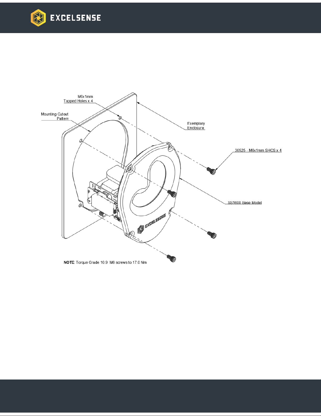
Enclosure Mounting Instructions
See below diagram for overview of mounting process:
Note: Mounting cut pattern is available upon request.
Note: It is recommended to design the 4 M6 mounting holes to be blind tapped holes. This
ensures no ingress of moisture or dust through the mounting points.
12

Accessories
Programming Cable: PA-SS16-USB
Serial communication cable provides a USB interface for the SensorShield-1600™’s Modbus
RTU service. Through this service it is possible to change the self-cleaning frequency, read the
number of cleaning cycles performed and read other diagnostic data.
Trigger Box: TB-FW-05M
Trigger Box provides a convenient method for manual triggering of a self-cleaning cycle. It
requires an input voltage between 5V-24V and the SensorShield-1600’s trigger wire.
Custom Enclosure
SensorShield-1600™ is sold un-enclosed. Contact an Excelsense representative to discuss the
option of having a customized enclosure designed
Triggering the SensorShield-1600™
The SensorShield-1600™ performs cleaning cycles in response to a trigger event. The
triggering event method is an important consideration at the time of specifying your system
topology. The decision is based on many factors, including availability of a digital switch, remote
triggering requirements, and the general nature of the application. Below are the recommended
options for triggering the device:
Manual Trigger
The manual trigger method is based on an external digital input (see Electrical Specifications for
acceptable input voltage range). The device accepts a positive signal pulse as a trigger input
and responds with a single, complete cleaning cycle, initiating its clean at the rising edge of the
pulse. A cleaning cycle is defined as a 360° glass lens rotation. Only when the device has
completed this cleaning cycle will it respond to subsequent trigger events. Note that due to its
edge-sensitive triggering behavior, the device will not perform multiple cleaning cycles if the
trigger wire is held at a logic high state. The pulse sequence shown below will initiate a
SensorShield-1600™ cleaning cycle.
13

Manual Trigger Pulse Diagram
Logic Level
Trigger Voltage
Step 1
Logic Low
0V or Open
Step 2
Logic High
5V ~ VIN (DC voltage)
Step 3
Logic Low
0V or Open
The recommended minimum hold time at a logic level state, tMIN, is 0.5 seconds. Using this
control, the SensorShield-1600TM can be configured for the use case seen below.
Manual Trigger using External Button
In manual trigger applications where on-demand vision is required, the trigger can be simply
wired to a normally-open momentary button as shown below.
14

Connect the TRIG wire of a Trigger Box to the trigger terminal of the power board (shown
above), and the Vin wire of the Trigger Box to a suitable voltage supply.
Automatic Trigger
The SensorShield-1600™ can be configured to perform self-cleaning cycles at a regular
interval. Please refer to the Modbus section for details on this configuration.
Thermal Subsystem
SensorShield-1600™ can be configured to provide a thermal subsystem for defrosting
capabilities, as an option. When ordering, specify SS16XSS-NR for this option. The defrost
subsystem directly heats the inner surface of the glass shield, in order to help remove built-up
ice or frost on the outer surface of the glass.
15

SensorShield-1600 Thermal Subsystem
Units equipped with the thermal defrost system (SS16-X__-__) have a thermal control algorithm.
This algorithm is designed to defrost ice build-up on the lens and prevent the system from
operating prior to defrosting.
The thermal subsystem protection will engage when the system reaches 7°C and will continue
heating until the inner glass temperature reaches a threshold of 15°C. Cleaning will be disabled
while the thermal subsystem is below 7°C, then will become enabled once the system is at or
above 7°C.
Note: For units which are not equipped with the thermal defrost system (SS16-S__-__), it is not
recommended to operate SensorShield-1600™ in icy conditions. Doing so may cause damage
and void the warranty.
16

SensorShield-1600™ Modbus-RTU Interface
This section outlines the SensorShield-1600™ Modbus-RTU interface, implemented through the
RS-232 protocol, including register definitions and functionality, as well as triggering and
operation.
SensorShield-1600 Modbus Interface
ExcelSense provides a simple graphical interface for viewing and modifying key settings.
The tool can be installed as follows:
1. Download the tool:
https://drive.google.com/drive/folders/1E_w-JkIgclwSMgNu5A-LXEUICokxBnzd?usp=sh
are_link
2. Unpack SensorShield1600ModbusClientAppPackage_v1.0_2023-04-28.zip to an
accessible location on your computer
3. Run the file SensorShield1600ModbusClientApp.exe
The SensorShield-1600 can then be configured as follows:
1. Ensure the device is powered, according to the instructions in the Typical Installations
section
2. Connect the PA-SS16-USB adapter cable to the 4 pin connector shown below:
17

3. Once connected, use Windows Device Manager to determine which USB COM port is in
use for this connection.
4. In the Serial Port dropdown shown below, enter the current COM port, then click the
Connect button.
18

Full details of the Modbus registers can be found in the following section. Modifying the
self-clean timeout can be easily done using the controls on the left side of the graphical
interface.
Modbus-RTU Settings
Modbus Settings
Device ID Address
The default Modbus-RTU device ID address is 0x01. This is modifiable through the DIDR
holding register on the Modbus server.
Modbus Data Addresses
All data addresses in Modbus messages are referenced to zero. The first occurrence of a data
item is addressed as item number zero. For example, the coil known as “coil 1” in a
programmable controller is addressed as coil 0x0000 in the data address field of a Modbus
message.
Internal Modbus Server Update Rate
Data stored in the Modbus registers and coils is scanned by the host system’s running program
approximately every 20 milliseconds. The maximum recommended scanning rate by a
Modbus-RTU client is 100ms.
RS-232 Settings
The SensorShield-1600™ device will host a Modbus-RTU server, running with the following
settings:
Baud Rate (bps)
38400
Data Bits
8
Stop Bits
1
Parity
None
Flow Control
None
19
Table of contents
Popular Industrial Equipment manuals by other brands


Zehnder Rittling
Zehnder Rittling ComfoFond-L Eco Series Installer manual

Texas Automation Products
Texas Automation Products ES-32 quick start guide

Pepperl+Fuchs
Pepperl+Fuchs LS611 Series manual

ABB
ABB ACS880-607LC Hardware manual

York
York P XU Series User's information, maintenance and service manual

ABB
ABB HT567437 Operation manual