Litter-Robot Open Air User manual

CONNECT UPGRADE KIT INSTALLATION GUIDE
DISASSEMBLE YOUR LITTER-ROBOT
1. Press the Power button to turn the unit o and
unplug it from the wall. Remove the Bonnet, Globe,
and Waste Drawer.
2. The plastic component that covers the Control Panel
on the Base is called the Bezel. Unscrew the 5 screws
to remove the Bezel.
Upgrade Kit includes:
• Main Circuit Board
• WebConnect Module
• Wire Harness
• Applique
• Serial Number Stickers
• Connect Quick Start Guide
Open Air
4. Separate the Bezel from the Control Panel by pushing
the buttons through and lifting up. Set the Bezel and
screws aside.
Note: The Circuit Board and Keypad may be held in
place by a piece of tape (assembly aid). If present,
simply remove it; it is not required for reassembly.
Figure 1
1
Installation Video
Contact Customer Service
Monday - Friday, 9am - 7pm ET
1-877-250-7729 or support@litter-robot.com LR3-8060-0a
Figure 2
3. Lift the Bezel out of place; if needed, use needle-
nose pliers for assistance.
Figure 3
You will need:
• #2 Phillips screwdriver
Installation video at litter-robot.com/upgradekitinstall
Optional:
• Needle-nose pliers
• Utility knife

REMOVE THE CIRCUIT BOARD
5. Turn the Circuit Board over and unplug the three
connectors: 4-pin (DFI - Drawer Full Indicator), 6-pin
(Motor and power), and the 8-pin (Hall Eect sensor).
Make sure to pull the connector from the base of the
wire.
6. Peel the Keypad away from the Circuit Board for
reuse.
7. Attach the Keypad to the new Circuit Board by sliding
the long edge of the Circuit Board under the rubber
lip, then working your way around the perimeter until
the Keypad frames the Circuit Board.
Note: If you think you may have confused the new
Circuit Board for Connect with the original one, see
Figure 28 on Page 7.
8. From the front of the Keypad, press the three
connection points through the holes on the Circuit
Board to secure them together (see Figure 8b).
Figure 6
Figure 5
Figure 4
2
Figure 7
Figure 8a Figure 8b
INSTALL THE NEW CIRCUIT BOARD

9. Reattach the three wire connectors to the Circuit
Board.
Each connector is keyed (there is a top and bottom),
so it will only fit on the header one way (see Figure 9).
If you feel resistance, turn it over and try again.
The 4-pin connector goes on the 4-pin header, the
6-pin connector goes on the 6-pin header, and the
8-pin connector goes on the 8-pin header as shown
in Figure 10a.
Note: The 4-pin header to the right of the 8-pin
header is used in the next step.
11. Connect the other end of the wire harness to the
4-pin header on the WebConnect module.
3
10. On the Circuit Board, connect the new wire harness
to the unused 4-pin header (see Figure 11a).
Figure 10a Figure 10b
4-pin
6-pin
8-pin
Figure 9
Key
Figure 12
Figure 11a Figure 11b
INSTALL THE WEBCONNECT MODULE

13. Tuck the WebConnect wire harness down into the
wire channel.
4
B. WITH RIBS (see Figure 15):
If your Base has ribs, slide the module into the ribs;
orient the module so the wire connector is at the top
(see Figure 16).
12. Depending on your Base, install the WebConnect
module using one of the following methods:
A. WITHOUT RIBS (see Figure 13):
If your Base does not have ribs, ax the module
to the front wall of the Base with the foam tape
provided (see Figure 14a).
Peel o the backing of the tape, orient the module so
the wire connector is at the top, and press it against
the front wall of the Base as shown in Figure 14b.
Figure 17
Figure 16
Figure 13
Figure 14a
No Ribs
Figure 15
Ribs
Figure 14b

14. Make sure the wires attached to the Circuit Board are
tucked behind it in the wire channel (see Figure 19).
5
Figure 18
Figure 19
15. Reassemble the Bezel onto the Circuit Board and
Keypad by holding the Circuit Board upright and
fitting the Bezel over it, so the buttons come through
the Control Panel.
Make sure to keep the Keypad wrapped around the
edges of the Circuit Board.
16. Make sure the edges of the Bezel rest flush with the
Base.
Once in place, look through the opening where the
black Gear protrudes and make sure no wires are
visible. If wires are visible, remove the Bezel, tuck
them into the wire channel, and secure them with
stretchable tape if necessary.
REATTACH THE BEZEL
Figure 20
Figure 21
Figure 22
17. Attach the Bezel by tightening the 5 screws. Do not
overtighten.

6
Figure 24
Figure 25
Figure 23
19. Apply the new black applique. Peel o the backing
and align the inner edge of the applique with the
plastic outline as shown in Figure 24. Press on firmly.
REPLACE THE APPLIQUE
AFFIX THE SERIAL NUMBER STICKER
20. Ax the new serial number sticker to the back of
the Base. Place it above the Cat Sensor foot in the
indented area as shown in Figure 25.
WARNING: Do not readjust; sticker reads VOID if
peeled o.
Note: This serial number sticker is required for
onboarding and service of your unit.
18. Remove the blue applique from the front of the
Bezel. Use your fingernail or a utility knife to pry up
the edge, then peel it o.

7
Contact Customer Service
Monday - Friday, 9am - 7pm ET
1-877-250-7729 or support@litter-robot.com LR3-8060-0a
21. Reassemble the Globe, Bonnet, and Waste Drawer.
Plug the unit in, power it on, and let the initial Clean
Cycle finish. The Globe should return to the Home
position with the blue Ready light on.
Troubleshoot
If your unit does not cycle or does not cycle properly,
review your installation:
If the unit will not turn on and appears to have no
power, check that the 6-pin connector (that holds
the wires to the Motor and power) is secured to the
Circuit Board in the correct orientation.
If the blue light is flashing, check that the 4-pin
connector (that holds the DFI wires) is secured to the
Circuit Board in the correct orientation.
If the red light is flashing, check that the 8-pin
connector (that holds the Hall Eect sensor wires)
is secured to the Circuit Board in the correct
orientation.
REASSEMBLE YOUR LITTER-ROBOT
ONBOARD YOUR LITTER-ROBOT
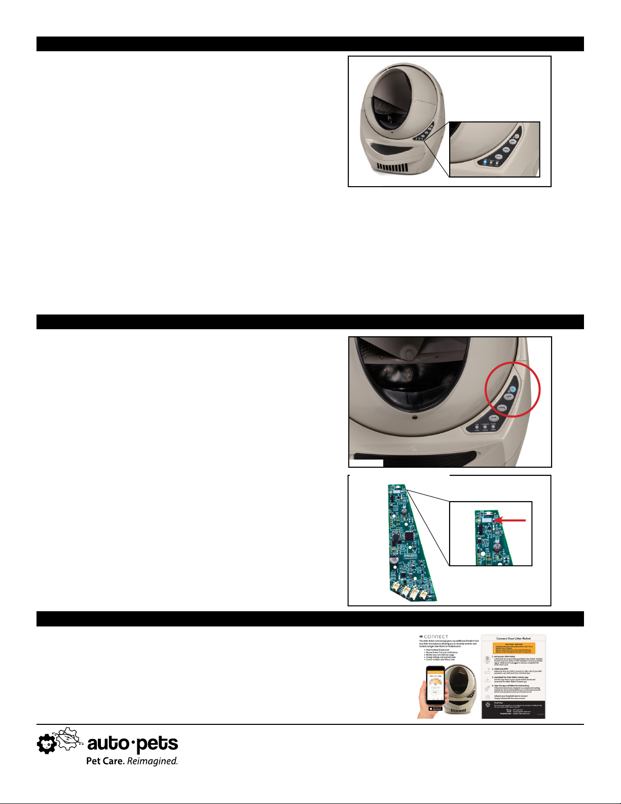
22. Press and hold the Cycle and Empty buttons until the
Power button turns blue (see Figure 27). Your unit is
in WiFi Mode. To exit, press the Reset button.
Troubleshoot
If the Power button does not turn blue, review your
installation:
Make sure the 4-pin connectors on the wire harness
are secured to the Circuit Board and WebConnect
module in the correct orientation.
Ensure that you have installed the new Main Circuit
Board for Connect. Look for the horizontal white
rectangle at the top of the board, as shown in Figure
28. Note: Original Main Circuit Boards may vary.
Congratulations! You have successfully upgraded your Litter-Robot.
Follow the Connect Quick Start Guide to onboard your Litter-Robot and
connect to the app.
Figure 27
Figure 26
Figure 28
Main Circuit Board for Connect
TEST YOUR INSTALLATION
Other Litter-Robot Household Appliance manuals