Little Giant RFSN-6 User manual

INTRODUCTION
The Little Giant liquid level control is designed to be used with
Little Giant Effluent and Sewage pumps or other pumps rated 13
Amps or less.
Little Giant products are carefully packaged, inspected and tested
to insure safe operations and delivery. When you receive your
switch, examine it carefully to determine that there are no parts
missing or which may have been damaged or broken during
shipment. If damage has occurred, make notation and notify
and/or return to the firm from which you purchased the switch and
they will assist you in replacement or repair.
SAFETY GUIDELINES
1. Read all instructions and safety guidelines thoroughly. Failure
to follow guidelines and instructions could result in serious
bodily injury and/or property damage.
2. During operation, the area around the pump and switch may
be covered with water. Take care when handling switch or
pump. Do not pull pump out of the water by the power cord.
3. Disconnect all electrical service to the pump and unplug the
pump and/or switch before working on the unit or handling the
unit.
4. Make sure all outlets used are grounded.
5. Do not stand in water while changing fuses, resetting circuit
breakers or repairing switch or pump.
1
RFSN-6
RFSN-9
RFSN-10
Liquid Level Control
Non-Mercury/Float Type
Figure 1.
Figure 2.
Franklin Electric Co., Inc.
P. O. Box 12010
Oklahoma City, OK 73157-2010
405.947.2511 • Fax: 405.947.8720
www.LittleGiantPump.com
CustomerService-[email protected]

2
SWITCH ADJUSTMENTS
(approximate measurements, in inches)
Pumping Range
(Dim “A”) 5.5 6 8 12 13 18 19 23 25
Tether Length
(Dim “B”) 3 4 6 8 10 12 13 15 17
TESTING
Without water in sump, plug pump cord into the back of the switch
plug. Plug switch into outlet. Lift float and listen for pump to
operate. Do not run pump for more than 5 seconds. Next, run
water into sump where pump is installed. Fill the sump to the “on”
level and allow the pump to remove water to the “off” level. Make
adjustment per chart on opposite page if needed.
DIRECT WIRING
FOR DIRECT WIRING INSTALLATION, REFER TO FIGURE 3
(SCHEMATIC).
WARNING: In a 230V direct wire installation, one side of the line
going to the pump is always “HOT”. This condition exists whether
the float switch is “ON” or “OFF”. To avoid hazards when installing
or servicing, install a double-pole disconnect near pump
installation.
Check local electrical and building codes before installing. This
installation must be in accordance with their regulations as well as
the most recent edition of the National Electrical Code Handbook
(NEC).
MANUAL PUMP OPERATION POSSIBLE BY PLUGGING PUMP
DIRECTLY INTO OUTLET. (Plug configuration may vary depending
on voltage.)
NOTE: Little Giant Pump Co. cannot be responsible for damages
caused by the faulty or negligent installation of this control. If you
feel that you may encounter problems in installing this device, we
respectfully suggest you engage the services of a competent
plumber, electrician, or qualified service person.
ADDITIONAL INFORMATION
CAUTION: To prevent damage to pump, do not set switch turn-off
level below 2" above bottom of pump base. Also, be sure that the
pump is secured in its position so the float will not become stuck
between the pump and the basin, which could prevent the pump
from turning “ON” or “OFF”. Be sure the cable tie is secure so the
switch cord does not accidentally slip and change the pre-set ON/
OFF levels.
ELECTRICAL CONNECTIONS
1. The level control switch is supplied with three-prong grounding
plug. The switch must be used with pumps that are equipped
with three-prong grounding plugs. Do not remove the third pin
from the plug. The receptacles should be properly grounded,
grounding-type receptacle.
2. Separate branch circuit is recommended. Do not use extension
cord.
3. Be sure electrical connections cannot be reached by rising
water. Under no circumstances should outlet box or receptacle be
located where it may become flooded or submerged by water.
INSTALLATION
If screw which is provided is lost, use only a #10-16 x ½" long
tapping screw. Longer screws can crack the cover.
1. Attach cord clamp to pump cover as shown. The clamp and
pump handle must be positioned as shown to allow free
operation of float. Be sure to locate and switch power cords
away from switch float.
2. A minimum tether length of 3½" is recommended for use on
the #6E, #8E, #8S, #9E, #9S, 9EH, #10E, and #10S series
pumps. Tether length to be 3½" when attached to pump on the
#6 series pumps. The tether length is measured as shown in
Figure 2.
3. A sump with a minimum diameter of 14" is required for the #6
series sump pumps.
4. A sump with a minimum diameter of 18" is required for the
#6E, #8E, #8S, #9E, #9S, #9EH, #10E and 10S series
pumps.
5. After desired tether length is established, hand tighten clamp
screw.
6. For universal installation, refer to Figure 1.
a. Attach switch cord using the cable tie provided to any
convenient rigid surface about 2" below the desired turn-on
level. Do not tighten cable tie until turn-on and turn-off
levels are established
b. Increase cord length between float and tie point increases
on-off differential. Decreasing cord length between float and
tie point decreases on-off differential.
c. Tighten cable tie securely after turn-on and turn-off levels
are established.
CAUTION: To prevent damage to pump, do not set switch turn-off
level below 2" above bottom of pump base. Also be certain that
pump is secured in position so float cannot become stuck
between the pump and the basin which could prevent pump from
coming on or going off. Be certain cable tie is secure so switch
cord does not accidentally slip and change set on/off levels.

3
LIMITED WARRANTY
Your Little Giant product is guaranteed to be in perfect condition
when it leaves our Factory. It is warranted against defective mate-
rials and workmanship for a period of 12 months (90 day warranty
on Models: 1-AA-OM, GKPK-SC, PP-1, PPS-1, PP-12, PPS-12 ,
PP-230 and Cooler King) from date of purchase by the end user.
No warranty on brush wear in Model 35-OM and impeller or cam
in Models PP-1, PP-12, and PP-230. Any product that should fail
for either of the above two reasons and is still within the warranty
period will be repaired or replaced if returned prepaid to our
Factory. All defective product returned under warranty will be fully
inspected to determine “cause of failure” before warranty is
approved. Little Giant will honor the warranty within the warranty
time period specified on satisfactory written proof of purchase.
DISCLAIMER: Any oral statements about the product made by the
seller, the manufacturer, the representatives or any other parties,
do not constitute warranties, shall not be relied upon by the user,
and are not part of the contract for sale. Sellers and manufacturers
only obligation, and buyers only remedy, shall be the replacement
and/or repair by the manufacturer of the product as described
above. Neither seller nor the manufacturer shall be liable for any
injury, loss or damage, direct, incidental or consequential (includ-
ing, but not limited to, incidental or consequential damages for
lost profits, lost sales, injury to person or property, or any other
incidental or consequential loss), arising out of the use or the
inability to use the product, and the sure agrees that no other
remedy shall be available to it. Before using, the user shall deter-
mine the suitability of the product for his intended use, and user
assumes all risk of liability whatsoever in connection therewith.
The warranty and remedy described in this limited warranty is an
EXCLUSIVE warranty and remedy and is IN LIEU OF any other
warranty or remedy, expressed or implied, which other warranties
and remedies are hereby expressly EXCLUDED, including but not
limited to any implied warranty of MERCHANTABILITY OR FITNESS
FOR A PARTICULAR PURPOSE. Some states do not allow the
exclusive or limitation of incidental or consequential damages, so
the above limitation or exclusion may not apply to you. This war-
ranty gives you specific legal rights, and you may also have other
rights which vary from state to state.
Warranty will be VOID if any of the following conditions are
found:
1. Sealed motor housing opened.
2. Product connected to voltage other than indicated on
nameplate.
3. Cord cut off to a length less than three feet.
4. Pump allowed to operate dry (fluid supply cut off).
5. Pump used to circulate anything other than fresh water, light
oils, or other mild liquids at approximately room temperature.
6. Product abuse by customer.
The National Electric Code requires a Ground Fault Circuit
Interrupter (GFCI) be installed in the branch circuit supplying foun-
tain equipment rated above 15 volts. Part number 599335, GFCI-1,
is in stock and we recommend each pump be used with a GFCI.

For Parts or Repair, please contact . . . . . . . . . . . . . . . . . . . . . . . . . . . . . . . . . . . .1.888.572.9933
For Technical Assistance, please contact . . . . . . . . . . . . . . . . . . . . . . . . . . . . . . .1.888.956.0000
www.LittleGiantPump.com
CustomerService-[email protected]
Form 994319 - 09/2006
©2008 Franklin Electric Co., Inc.
Little Giant® is a registered trademark of Franklin Electric Co., Inc.
Other manuals for RFSN-6
1
This manual suits for next models
2
Other Little Giant Switch manuals
Little Giant
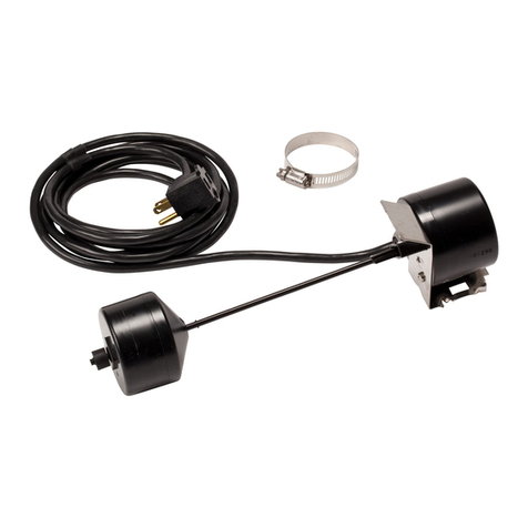
Little Giant RVMS User manual

Little Giant
Little Giant VDS Series User manual
Little Giant
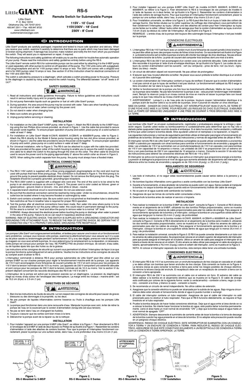
Little Giant RS-5 User manual

Little Giant
Little Giant ACS-3 Use and care manual
Little Giant
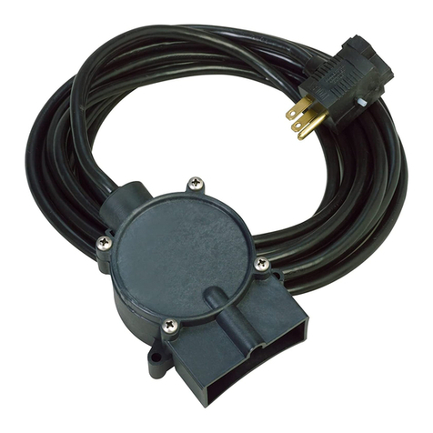
Little Giant RS-5 User manual

Little Giant
Little Giant RS-5LL Reference manual

Little Giant
Little Giant RS-5 User manual

Little Giant
Little Giant RFSN-6 User manual
Little Giant
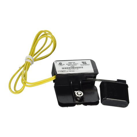
Little Giant ACS-2 Manual
