manuals.online logo
Brands
  1. Home
  2. •
  3. Brands
  4. •
  5. Omron
  6. •
  7. Switch
  8. •
  9. Omron B3SL User manual

Omron B3SL User manual

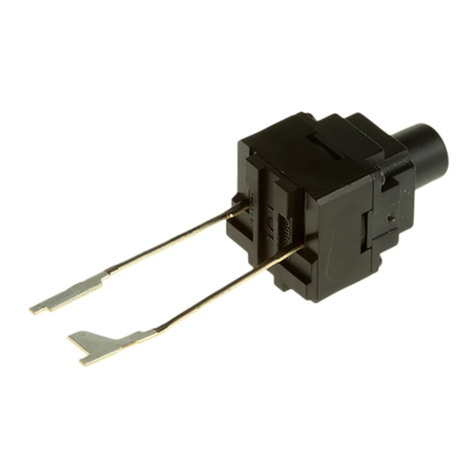
Middle Stroke Tactile Switch B3SL 251
Middle Stroke Tactile Switch
B3SL
Surface-mount Sealed Tactile Switch with
Mid-length Pretravel and Crisp Clicking
Action.
•90°C Maximum operating Temperature
• Sealed construction conforming to IP67 (IEC 60529)
provides high contact reliability in dusty environments.
• Crisp click feeling and middle stroke with rubber plunger.
• Two heights available, 3.4 mm and 5.1 mm
• Tape packing is available
• RoHS Compliant
Ordering Information
Note: Order in multiples of the quantities given. Switches are not sold individually.
Specifications
■Characteristics
Note: Data shown are of initial value
■Operating Characteristics
Type Plunger Height Operating force (OF) Embossed tape
Model Quantity per reel
6 x 6 mm
B3SL Series
(Flat type)
3.4 mm 1.96 N (200 gf) B3SL-1002P 2,000
(Flat type)
5.1 mm B3SL-1022P 1,400
Contact form SPST-NO
Switching capacity 1 to 50 mA at 5 to 12 VDC (resistive load)
Contact resistance 100 mΩ max. (rated: 1 mA at 5 VDC)
Insulation resistance 100 MΩmin. (at 250 VDC)
Dielectric strength 250 VAC, 50/60 Hz for 1 min.
Bounce time 5 ms max.
Vibration resistance Destruction: 10 to 55 Hz, 1.5-mm double amplitude
Shock resistance Destruction: 1,000 m/s2 (approx. 100 G) max.
Ambient operating temperature −25 to 90°C (at 60% RH max.) with no icing or condensation
Ambient operating humidity 35% to 85% (at 5 to 35°C)
Service Life 100,000 operations min.
Characteristics B3SL-1002P B3SL-1022P
Operating force (OF) 200 ±50 gf (1.96 ±0.49 N)
Release force (RF) min. 35 gf (0.35 N)
Pretravel (PT) 0.3 ±0.2 mm 0.5 ±0.2 mm
252 Middle Stroke Tactile Switch B3SL
Dimensions
Note: Unless otherwise specified, all units are in millimeters and a tolerance of ±0.2mm applies to all dimensions.
B3SL-1002P
B3SL-1022P
Precautions
■Precautions for Correct Use
Storage
Storage Environment
To prevent degradation, such as discoloration of the terminals during
storage, do not store the Switch in locations that are subject to the
following conditions;
•High temperature or humidity
•Corrosive gases
•Direct sunlight
Storage condition
Store the Switches in the packaging box.
After the packaging box is opened, use the contents as quickly as
possible. When storing leftover parts, make sure that appropriate
measures are taken against humidity and corrosive gases.
Handling
Usage Environment
Before installing the Switch, make sure that the area of installation is
not subject to corrosive gases emitted from surrounding parts.
1. Do not use in areas subject to high temperatures, high humid-
ity, or toxic gases such as sulfuric gas (H2S, SO2), ammonia
gas (NH3), nitric gas (HNO3), or chlorine gas (CI2). It can
cause corrosive damage to the contacts and result in mal-
function.
2. If there is silicon in the atmosphere, it may stop the contacts
from functioning properly. If silicon products, such as silicon
oil, silicon filler, or silicon wires, are used in the surrounding
area, install a contact protection circuit to prevent arching or
remove the silicon source. The Switch is not completely
sealed. The following situations may cause water to enter
inside the Switch, resulting in a malfunction due to contact
failure or corrosion.
•Using the Switch in an outdoor environment where it is
exposed to water drops for an extended period of time
•Using the Switch in an underwater setting where it is sub-
ject to strong water pressure.
Operation
•Do not repeatedly operate the Switch with excessive force.
Applying excessive pressure or applying additional force after the
plunger has stopped may deform the disk spring of the Switch,
resulting in malfunction. (Maximum force = 30N)
•Be sure to set up the Switch so that the plunger will operate in a
straight vertical line. If the plunger is pressed off-center or from an
angle it may cause deformation or damage to some parts. This may
result in deterioration of life expectancy or malfunction.
4±0.2
6.2
6.5
0.1 7
6.5
1.2
3
3
8.5
5
0.7
2.5 dia.
3.4 2.5
4
2
3
1
PCB Pad
(Top View)
Terminal Arrangement/
Internal Connections
(Top View)
4
±0.2
6.2
6.5
3
3
8.5
5
6.5
1.2
0.7
0.1 7
2.5 dia.
5.1
2.5
4
2
3
1
PCB Pad
(Top View)
Terminal Arrangement/
Internal Connections
(Top View)
Middle Stroke Tactile Switch B3SL 253
Electrical Operation
Use the Switch within the rated voltage and current ranges, other-
wise the Switch may have a shortened life expectancy, radiate heat,
or burn out. This particularly applies to the instantaneous voltages
and currents when switching.
Soldering
Soldering Precautions
1. Before any kind of soldering, test to confirm that soldering can
be performed properly. Otherwise the Switch may be
deformed by the soldering heat depending on the type of
PCB, pattern, or lands of the PCB.
2. Do not solder the Switch more than twice, including rectifica-
tion soldering. Wait for at least five minutes between the first
and second soldering to allow the temperature to return to
normal. Continuous soldering may cause the casing to melt or
deteriorate the Switch characteristics.
Reflow Soldering Conditions
Firmly attach a thermocouple to the surface of the terminals with sol-
der that has a high melting point and set the reflow oven so that the
peak temperature of the terminals is 260°C or less.
The following figure shows the temperature profile.
Manual Soldering
1. Soldering temperature: 350°C max. at the tip of the soldering
iron
2. Soldering time: 3 s max. for a 1.6-mm thick, single-side PCB
Washing
Standard Switches are not sealed, and cannot be washed.
Doing so will cause the washing agent, together with flux or dust
particles on the PCB, to enter the Switch, resulting in malfunction.
Applicable Printed Circuit Board
The Switch is designed for a 1.6-mm thick, single-side PCB.
Using PCBs with a different thickness or using double-sided,
through-hole PCBs may result in loose mounting, improper insertion,
or poor heat resistance in soldering. These effects will occur,
depending on the type of holes and patterns of the PCB. Therefore, it
is recommended that a verification test is conducted before use.
RoHS Compliant
The "RoHS Compliant" designation indicates that the listed models
do not contain the six hazardous substances covered by the RoHS
Directive.
Reference:
The following standards are used to determine compliance for the six
substances.
Lead: 1,000 ppm max.
Mercury: 1,000 ppm max.
Cadmium: 100 ppm max.
Hexavalent chromium: 1,000 ppm max.
PBB: 1,000 ppm max.
PBDE: 1,000 ppm max.
Packaging Specifications
The packaging specifications for B3SL Switches in embossed taping
are given below.
B3SL-1002P
B3SL-1022P
Common Precautions
Be sure to read the precautions common to all Tactile Switches, con-
tained in the Technical User’s Guide, “Tactile Switches, Technical
Information” for correct use.
Temperature
(°C)
180
220
260 max.
150 Preheating time Main
heating
time
Time (s)
60 to 120 60 max.
Standards Conforms to JIS.
Package 2,000 Switches (B3SL-1002P)
1,400 Switches (B3SL-1022P)
Heat resistance 60°C for 24 hours (without deformation)
4
±0.1
2
16
7.5
1.75
12
±0.1
1.5+0.1
0 dia.
Tape drawing direction
(3.7)
380±2
dia.
13 dia.
Reel (Material: PS)
Label
(22)
Tape drawing
direction
(5.3)
2
16
7.5
1.75
4
±0.1
12
±0.1
1.5+0.1
0 dia.
Tape drawing direction
380±2
dia.
13 dia.
Reel (Material: PS)
Label
(22)
Tape drawing
direction
Middle Stroke Tactile Switch B3SL
OMRON ON-LINE
Global - http://www.omron.com
USA - http://www.components.omron.com
Cat. No. X303-E-1 Printed in USA
OMRON ELECTRONIC
COMPONENTS LLC
55 E. Commerce Drive, Suite B
Schaumburg, IL 60173
847-882-2288
11/10 Specifications subject to change without notice
All sales are subject to Omron Electronic Components LLC standard terms and conditions of sale, which
can be found at http://www.components.omron.com/components/web/webfiles.nsf/sales_terms.html
ALL DIMENSIONS SHOWN ARE IN MILLIMETERS.
To convert millimeters into inches, multiply by 0.03937. To convert grams into ounces, multiply by 0.03527.

Other Omron Switch manuals

Omron EN 60947 - User manual

Omron

Omron EN 60947 - User manual

Omron A User manual

Omron

Omron A User manual

Omron SHL - User manual

Omron

Omron SHL - User manual

Omron D4CC - User manual

Omron

Omron D4CC - User manual

Omron ZC-55 - User manual

Omron

Omron ZC-55 - User manual

Omron D4DL User manual

Omron

Omron D4DL User manual

Omron D4BL - User manual

Omron

Omron D4BL - User manual

Omron A2W-R**-WC1 Series User manual

Omron

Omron A2W-R**-WC1 Series User manual

Omron D5C User manual

Omron

Omron D5C User manual

Omron D4GL-1AFA-A4 User manual

Omron

Omron D4GL-1AFA-A4 User manual

Omron SS Series User manual

Omron

Omron SS Series User manual

Omron D7E User manual

Omron

Omron D7E User manual

Omron D4GS-N - User manual

Omron

Omron D4GS-N - User manual

Omron A22E-MP User manual

Omron

Omron A22E-MP User manual

Omron ER1022 User manual

Omron

Omron ER1022 User manual

Omron D40B - User manual

Omron

Omron D40B - User manual

Omron A3A Series User manual

Omron

Omron A3A Series User manual

Omron ER5018 User manual

Omron

Omron ER5018 User manual

Omron D4NS - User manual

Omron

Omron D4NS - User manual

Omron D4B-N - User manual

Omron

Omron D4B-N - User manual

Omron D4N-R - User manual

Omron

Omron D4N-R - User manual

Omron G9SX Series User manual

Omron

Omron G9SX Series User manual

Omron E3L-2 4 Series User manual

Omron

Omron E3L-2 4 Series User manual

Omron A4E User manual

Omron

Omron A4E User manual

Popular Switch manuals by other brands

Bticino RW4570CW manual

Bticino

Bticino RW4570CW manual

Linksys SFE2000 Quick installation guide

Linksys

Linksys SFE2000 Quick installation guide

Balluff BES M30MF2-PSC10B-BV02-EXD user guide

Balluff

Balluff BES M30MF2-PSC10B-BV02-EXD user guide

Altronix NetWaySP8WP installation manual

Altronix

Altronix NetWaySP8WP installation manual

Encore ENH908-NWY Features

Encore

Encore ENH908-NWY Features

GEV AURORA MINI LCI 16903 manual

GEV

GEV AURORA MINI LCI 16903 manual

Soltech SFC8000HP user manual

Soltech

Soltech SFC8000HP user manual

Gefen EXT-HDMI1.3-841 user manual

Gefen

Gefen EXT-HDMI1.3-841 user manual

HP ProCurve 1400-24G Installation and getting started

HP

HP ProCurve 1400-24G Installation and getting started

Sigma SLX series Operator's manual

Sigma

Sigma SLX series Operator's manual

IFM Electronic G Series operating instructions

IFM Electronic

IFM Electronic G Series operating instructions

SICK ES11 operating instructions

SICK

SICK ES11 operating instructions

ZyXEL Communications PMG5318-B20B quick start guide

ZyXEL Communications

ZyXEL Communications PMG5318-B20B quick start guide

Cisco Cisco Small Business Unmanaged Switch SR2016 quick start guide

Cisco

Cisco Cisco Small Business Unmanaged Switch SR2016 quick start guide

Infinitybox 10-Circuit Kit installation guide

Infinitybox

Infinitybox 10-Circuit Kit installation guide

GRI PB-2020 Series quick start guide

GRI

GRI PB-2020 Series quick start guide

Presentation Switchers PS112 user guide

Presentation Switchers

Presentation Switchers PS112 user guide

schmersal AZ 200 AS operating instructions

schmersal

schmersal AZ 200 AS operating instructions

manuals.online logo
manuals.online logoBrands
  • About & Mission
  • Contact us
  • Privacy Policy
  • Terms and Conditions

Copyright 2025 Manuals.Online. All Rights Reserved.