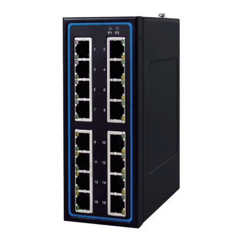
Atop EHG75 series User manual

Industrial Managed
Ethernet Switch
User Manual
Page 1of 190
Industrial Managed
Ethernet Switch
User Manual
V1.3
March 22nd, 2017
Series covered by this manual:
EHG75XX, RHG75XX*, EHG95XX*, EMG85XX*, EH75XX*
* The user interface on these products may be slightly different
from the one shown on this user manual
Atop Technologies, Inc.

Industrial Managed
Ethernet Switch
User Manual
Page 2of 190
This PDF Document contains internal hyperlinks for ease of navigation.
For example, click on any item listed in the Table of Contents to go to that page.
Published by:
Atop Technologies, Inc.
2F, No. 146, Sec. 1, Tung-Hsing Rd,
30261 Chupei City, Hsinchu County
Taiwan, R.O.C.
Tel: +886-3-550-8137
Fax: +886-3-550-8131
www.atoponline.com
www.atop.com.tw

Industrial Managed
Ethernet Switch
User Manual
Page 3of 190
Important Announcement
The information contained in this document is the property of Atop Technologies, Inc., and is supplied for the sole
purpose of operation and maintenance of Atop Technologies, Inc., products.
No part of this publication is to be used for any other purposes, and it is not to be reproduced, copied, disclosed,
transmitted, stored in a retrieval system, or translated into any human or computer language, in any form, by any
means, in whole or in part, without the prior explicit written consent of Atop Technologies, Inc.,
Offenders will be held liable for damages and prosecution.
All rights, including rights created by patent grant or registration of a utility model or design, are reserved.
Disclaimer
We have checked the contents of this manual for agreement with the hardware and the software described. Since
deviations cannot be precluded entirely, we cannot guarantee full agreement. However, the data in this manual is
reviewed regularly and any necessary corrections will be included in subsequent editions.
Suggestions for improvement are welcome. All other product’s names referenced herein are registered trademarks
of their respective companies.
Preface
This manual contains some advanced network management knowledge, instructions, examples, guidelines, and
general theories. The contents are designed to help users manage the switch and use its software, a background
in general theory is a must, when reading it. Please refer to the Glossary for technical terms and abbreviations.
Who Should Use This User Manual
This manual is to be used by qualified network personnel or support technicians who are familiar with network
operations, and might be useful for system programmers or network planners as well. This manual also provides
helpful and handy information for first time users. For any related problems, please contact your local distributor.
If they are unable to assist you, please redirect your inquiries to www.atop.com.tw.
Warranty Period
Atop technology provides a limited 5-year warranty for managed Ethernet switches.
Documentation Control
Author:
Matteo Tabarelli
Revision:
1.3
Revision History:
New format, new features, new default password
Creation Date:
07 June 2016
Last Revision Date:
29 March 2017
Product Reference:
Layer-2 Managed Switch
Document Status:
Released

Industrial Managed
Ethernet Switch
User Manual
Page 4of 190
Table of Contents
1Introduction ...............................................................................................................13
1.1 Introduction to Industrial Managed Switch.....................................................................................13
1.2 Software Features..........................................................................................................................14
2Configuring with a Web Browser................................................................................15
2.1 Web-based Management Basics ...................................................................................................15
2.1.1 Default Factory Settings .................................................................................................................15
2.1.2 Login Process and Main Window Interface....................................................................................16
2.2 Basic Information............................................................................................................................17
2.2.1 Sys Info...........................................................................................................................................17
2.2.2 Device Information Setting.............................................................................................................18
2.2.3 Console Setting ..............................................................................................................................19
2.2.4 Protocols Status.............................................................................................................................19
2.2.5 Power Status ..................................................................................................................................20
2.2.6 Temperature Log ............................................................................................................................20
2.3 Administration.................................................................................................................................22
2.3.1 Password........................................................................................................................................22
2.3.2 IP Setting ........................................................................................................................................24
2.3.3 IPv6 Setting ....................................................................................................................................27
2.3.4 Ping ................................................................................................................................................29
2.3.5 Ping6 ..............................................................................................................................................30
2.3.6 Mirror Port ......................................................................................................................................31
2.3.7 System Time...................................................................................................................................32
2.3.8 Modbus Setting ..............................................................................................................................33
2.3.9 Precision Time Protocol (PTP).......................................................................................................41
2.3.10Secure Shell - SSH ..........................................................................................................................44
2.3.11Telnet..............................................................................................................................................45
2.3.12DIP Switch ......................................................................................................................................45
2.4 Forwarding .....................................................................................................................................46
2.4.1 QoS.................................................................................................................................................46
2.4.2 Rate Control....................................................................................................................................50
2.4.3 Storm Control .................................................................................................................................51
2.5 Port-related settings.......................................................................................................................53
2.5.1 Port Setting.....................................................................................................................................54
2.5.2 Port Status......................................................................................................................................55
2.5.3 Mini-GBIC Port Status ....................................................................................................................56
2.5.4 Port Statistics.................................................................................................................................56
2.6 Power over Ethernet.......................................................................................................................58
2.6.1 PoE Setting.....................................................................................................................................58
2.6.2 PoE Status......................................................................................................................................59
2.6.3 PoE Alarm Setting ..........................................................................................................................60
2.7 Trunking .........................................................................................................................................61
2.7.1 Trunking Setting .............................................................................................................................61
2.7.2 LACP Status ...................................................................................................................................63
2.8 Unicast/Multicast MAC...................................................................................................................65
2.8.1 Add Static MAC ..............................................................................................................................66
2.8.2 Black-List MAC...............................................................................................................................67
2.8.3 MAC Aging Time ............................................................................................................................67

Industrial Managed
Ethernet Switch
User Manual
Page 5of 190
2.8.4 MAC Table......................................................................................................................................68
2.9 GARP/GVRP/GMRP......................................................................................................................70
2.9.1 Multicast Group Table ....................................................................................................................70
2.9.2 GARP Setting ..................................................................................................................................71
2.9.3 GVRP Setting ..................................................................................................................................72
2.9.4 GMRP Setting .................................................................................................................................73
2.10 IP Multicast.....................................................................................................................................74
2.10.1IGMP...............................................................................................................................................75
2.10.2Static IP Multicast ..........................................................................................................................80
2.11 SNMP.............................................................................................................................................81
2.11.1SNMP Agent ...................................................................................................................................82
2.11.2SNMP V1/V2c Community Setting .................................................................................................83
2.11.3Trap Setting ....................................................................................................................................84
2.11.4SNMPv3 Auth. Setting....................................................................................................................84
2.12 Spanning Tree................................................................................................................................86
2.12.1Spanning Tree Setting ....................................................................................................................87
2.12.2Bridge Info ......................................................................................................................................89
2.12.3Port Setting.....................................................................................................................................90
2.12.4MSTP Instance ...............................................................................................................................93
2.13 VLAN..............................................................................................................................................94
2.13.1VLAN Setting ..................................................................................................................................95
2.13.2802.1Q VLAN..................................................................................................................................96
2.13.3Port-Based VLAN ...........................................................................................................................99
2.13.4MAC-Based VLAN ........................................................................................................................100
2.13.5IP Subnet-Based VLAN.................................................................................................................100
2.13.6Protocol-Based VLAN...................................................................................................................101
2.13.7QinQ..............................................................................................................................................102
2.14 Security ........................................................................................................................................104
2.14.1Port Security .................................................................................................................................104
2.14.2802.1X ..........................................................................................................................................106
2.14.3ACL ...............................................................................................................................................110
2.15 ERPS Ring ...................................................................................................................................113
2.15.1ESRP Setting.................................................................................................................................114
2.15.2iA-Ring Settings............................................................................................................................119
2.15.3C-Ring (Compatible-Ring)Settings ..............................................................................................121
2.15.4U-Ring...........................................................................................................................................121
2.15.5Compatible-Chain Settings...........................................................................................................124
2.16 LLDP.............................................................................................................................................127
2.16.1LLDP Settings...............................................................................................................................127
2.16.2LLDP Neighbors............................................................................................................................128
2.17 PROFINET ...................................................................................................................................130
2.17.1PROFINET Settings.......................................................................................................................130
2.17.2PROFINET’s I&M...........................................................................................................................131
2.17.3PROFINET MRP ............................................................................................................................131
2.18 EtherNet/IP...................................................................................................................................135
2.18.1EtherNet/IP Settings .....................................................................................................................136
2.19 Client IP Setting............................................................................................................................136
2.19.1DHCP Relay Agent ........................................................................................................................136
2.19.2DHCP Mapping IP.........................................................................................................................137
2.20 System .........................................................................................................................................138
2.20.1System Log...................................................................................................................................139
2.20.2Warning/Alarm..............................................................................................................................140
Industrial Managed
Ethernet Switch
User Manual
Page 6of 190
2.20.3Denial of Service...........................................................................................................................146
2.20.4Backup/Restore Config.................................................................................................................147
2.20.5Firmware Update ..........................................................................................................................151
2.20.6Factory Default Setting.................................................................................................................151
2.20.7Reboot ..........................................................................................................................................151
3Configuring with a Serial Console............................................................................152
3.1 Serial Console Setup....................................................................................................................152
3.2 Command Line Interface Introduction..........................................................................................153
3.3 General Commands.....................................................................................................................154
3.4 Command Example......................................................................................................................155
3.4.1 Administration Setup using Serial Console ..................................................................................155
3.4.2 Spanning Tree Setup using Serial Console...................................................................................156
4Configuring with a Telnet Console...........................................................................157
4.1 Telnet ...........................................................................................................................................157
4.2 Telnet Log-in ................................................................................................................................157
4.3 Command Line Interface for Telnet..............................................................................................157
4.4 Commands in the Privileged Mode ..............................................................................................158
4.5 Commands in the Configuration Mode.........................................................................................158
5Device Management Utility ......................................................................................161
5.1 Network Setting............................................................................................................................162
5.2 Topology Diagram........................................................................................................................163
5.3 Firmware Update..........................................................................................................................165
6Glossary ..................................................................................................................166
7Modbus Memory Map .............................................................................................168
8CIP supported objects of Ethernet/IP ......................................................................177
8.1 Identity Object ..............................................................................................................................177
8.2 TCP/IP Interface Object ...............................................................................................................178
8.3 Ethernet Link Object.....................................................................................................................180
8.4 Assembly Object ..........................................................................................................................184
8.5 Message Router Object (Not supported) ....................................................................................185
8.6 Connection Manager Object ........................................................................................................186
8.7 Port Object ...................................................................................................................................187
Table of Figures
Figure 2.1 IP Address for Web-based Setting .............................................................................................................. 16
Figure 2.2 Default Web Interface .................................................................................................................................. 16
Figure 2.3 Basic Information Dropdown Menu ............................................................................................................ 17
Figure 2.4 Details of Sys Info Webpage........................................................................................................................ 17
Figure 2.5 Details of Device Information Settings Webpage....................................................................................... 18
Figure 2.6 Setting Parameters for the Console Method .............................................................................................. 19
Figure 2.7 Protocol Status Webpage ............................................................................................................................ 19
Figure 2.8 Power Status Webpage................................................................................................................................ 20

Industrial Managed
Ethernet Switch
User Manual
Introduction
Page 7of 190
Figure 2.9 User Temperature Log ................................................................................................................................. 21
Figure 2.10 System Temperature Log .......................................................................................................................... 21
Figure 2.11 Administration Dropdown Menu ............................................................................................................... 22
Figure 2.12 Password Setting Webpage ...................................................................................................................... 22
Figure 2.13 Authentication Server Setting .................................................................................................................... 23
Figure 2.14 IP Setting under IP Setting Webpage ........................................................................................................ 25
Figure 2.15 IP Interface Part under IP Setting Webpage ............................................................................................. 25
Figure 2.16 IPv6 Setting Part of IPv6 Setting Webpage .............................................................................................. 27
Figure 2.17 Current IPv6 Address Information Part of IPv6 Setting Page.................................................................. 27
Figure 2.18 IP Interface for IPv6 Part of IPv6 Setting Webpage ................................................................................. 28
Figure 2.19 Ping Webpage............................................................................................................................................. 29
Figure 2.20 Example of Ping Command ....................................................................................................................... 29
Figure 2.21 Example of successful ping command result .......................................................................................... 29
Figure 2.22 Example of unsuccessful ping command result ...................................................................................... 30
Figure 2.23 Ping6 Webpage .......................................................................................................................................... 30
Figure 2.24 Example of Successful Ping6 Result ........................................................................................................ 30
Figure 2.25 Mirror Port Webpage.................................................................................................................................. 31
Figure 2.26 Webpage for Setting System Time and SNTP.......................................................................................... 32
Figure 2.27 Webpage for Setting the Modbus Address............................................................................................... 33
Figure 2.28 Mapping Table of Modbus Address for Switch’s IP Address.................................................................. 34
Figure 2.29 Entering Connection Setup Menu of the Modbus Poll ............................................................................. 34
Figure 2.30 Modbus Poll Connection Setup................................................................................................................. 35
Figure 2.31 Mulitple Cell Section in Modbus Poll......................................................................................................... 35
Figure 2.32 Set Display Mode to Hex in Modbus Poll.................................................................................................. 36
Figure 2.33 Modbus Poll Setup Read/Write Definition................................................................................................. 36
Figure 2.34 Slave ID in the Modbus Poll Function is set to 1 ...................................................................................... 37
Figure 2.35 Set Code 03 in the Modbus Poll Function................................................................................................. 37
Figure 2.36 Setup Starting Address and Quantity in Modbus Poll .............................................................................. 38
Figure 2.37 Modbus Memory Address 81 and 82 are the location of EHG7508's IP Address.................................. 38
Figure 2.38 Mapping Table of Modbus Address for Clearing Port Statistics............................................................. 39
Figure 2.39 Port Count in Port Statistics Webpage ..................................................................................................... 39
Figure 2.40 Click on Function 06 in the Modbus Poll .................................................................................................. 39
Figure 2.41 Use Modbus Poll to Clear Switch's Port Count......................................................................................... 40
Figure 2.42 Cleared Port Statistics ............................................................................................................................... 40
Figure 2.43 PTP's Submenu .......................................................................................................................................... 41
Figure 2.44 PTP Setting Webpage, example taken from EH75XX series ................................................................... 42
Figure 2.45 Hardware PTP Setting................................................................................................................................ 44
Figure 2.46 SSH Setting Webpage ................................................................................................................................ 44
Figure 2.47 Telnet Setting Webpage............................................................................................................................. 45
Figure 2.48 DIP Switch Status Webpage ...................................................................................................................... 45
Figure 2.49 Forwarding Dropdown Menu ..................................................................................................................... 46
Figure 2.50 QoS Dropdown Menu ................................................................................................................................. 46
Figure 2.51 QoS Setting Webpage ................................................................................................................................ 48
Figure 2.52 Mapping Table of CoS Webpage............................................................................................................... 49
Figure 2.53 Mapping Table of DSCP and ECN Webpage............................................................................................. 50
Figure 2.54 Rate Control Webpage ............................................................................................................................... 51
Figure 2.55 Storm Control Webpage............................................................................................................................. 52
Figure 2.56 Port Dropdown Menu ................................................................................................................................. 53
Figure 2.57 Port Setting Webpage ................................................................................................................................ 54
Figure 2.58 Port Status Webpage ................................................................................................................................. 55

Industrial Managed
Ethernet Switch
User Manual
Introduction
Page 8of 190
Figure 2.59 Mini-GBIC Port Status Webpage ............................................................................................................... 56
Figure 2.60 Port Statistics Webpage ............................................................................................................................ 57
Figure 2.61 Power over Ethernet Dropdown Menu example on EHG7508-4SFP-4PoE............................................. 58
Figure 2.62 PoE Setting Webpage example on EHG7508-8PoE ................................................................................. 58
Figure 2.63 PoE Status Webpage, example on EHG7508-8PoE.................................................................................. 59
Figure 2.64 PoE Alarm Setting ...................................................................................................................................... 60
Figure 2.65 Trunking Dropdown Menu ......................................................................................................................... 61
Figure 2.66 Trunking Setting Webpage, example with EH7520 .................................................................................. 62
Figure 2.67 LACP Webpage........................................................................................................................................... 64
Figure 2.68 Unicast vs. Multicast ................................................................................................................................. 65
Figure 2.69 Unicast/Multicast Dropdown Menu........................................................................................................... 66
Figure 2.70 Add Static MAC Webpage.......................................................................................................................... 67
Figure 2.71 Black-List MAC Setting Webpage ............................................................................................................. 67
Figure 2.72 MAC Aging Time Webpage........................................................................................................................ 68
Figure 2.73 MAC Table Webpage ................................................................................................................................. 68
Figure 2.74 GARP/GVRP/GMRP Dropdown Menu ........................................................................................................ 70
Figure 2.75 Multicast Group Table................................................................................................................................ 71
Figure 2.76 GARP Setting Webpage ............................................................................................................................. 71
Figure 2.77 GVRP Setting Box with Port Enabling ....................................................................................................... 72
Figure 2.78 GVRP Statistics .......................................................................................................................................... 72
Figure 2.79 GMRP Setting Box ...................................................................................................................................... 73
Figure 2.80 GMRP Statistics.......................................................................................................................................... 74
Figure 2.81 IP Multicast Dropdown Menu .................................................................................................................... 75
Figure 2.82 IGMP's Options ........................................................................................................................................... 75
Figure 2.83 IGMP Setting Webpage .............................................................................................................................. 76
Figure 2.84 Example of IGMP Proxy ............................................................................................................................. 77
Figure 2.85 IGMP's IP Multicast Table Webpage ......................................................................................................... 77
Figure 2.86 Example of IGMP's IP Multicast Table ...................................................................................................... 78
Figure 2.87 IGMP Statistics Webpage .......................................................................................................................... 78
Figure 2.88 Example of IGMP's Statistics..................................................................................................................... 79
Figure 2.89 Static IP Multicast Setting Webpage......................................................................................................... 80
Figure 2.90 Example of Static IP Multicast Setting ..................................................................................................... 81
Figure 2.91 SNMP Dropdown Menu.............................................................................................................................. 82
Figure 2.92 SNMP Enabling Box.................................................................................................................................... 82
Figure 2.93 SNMP Community Strings ......................................................................................................................... 83
Figure 2.94 Example of Trap Receiver Setting ............................................................................................................. 84
Figure 2.95 SNMPv3 Users' Options ............................................................................................................................. 85
Figure 2.96 Spanning Tree Dropdown Menu ................................................................................................................ 86
Figure 2.97 Spanning Tree Mode Setting ..................................................................................................................... 87
Figure 2.98 Spanning Tree Main Setting for STP and RSTP........................................................................................ 87
Figure 2.99 Spanning Tree Main Setting for MSTP...................................................................................................... 88
Figure 2.100 Spanning Tree Per-port Setting for STP and RSTP ................................................................................ 89
Figure 2.101 Bridge Information Webpage .................................................................................................................. 89
Figure 2.102 Spanning Tree Port Setting Webpage..................................................................................................... 91
Figure 2.103 MSTP Instance Webpage ........................................................................................................................ 93
Figure 2.104 Example of VLAN Configuration ............................................................................................................. 94
Figure 2.105 VLAN Dropdown Menu............................................................................................................................. 95
Figure 2.106 VLAN Setting Webpage............................................................................................................................ 95
Figure 2.107 802.1Q VLAN Dropdown Menu ............................................................................................................... 96
Figure 2.108 802.1Q VLAN’s Setting Webpage............................................................................................................ 97

Industrial Managed
Ethernet Switch
User Manual
Introduction
Page 9of 190
Figure 2.109 802.1Q VLAN PVID Setting Webpage ..................................................................................................... 98
Figure 2.110 802.1Q VLAN Table Webpage ................................................................................................................. 98
Figure 2.111 Example of 802.1Q VLAN Table.............................................................................................................. 99
Figure 2.112 Port-based VLAN Setting Webpage ...................................................................................................... 100
Figure 2.113 MAC-Based VLAN Setting Webpage..................................................................................................... 100
Figure 2.114 IP Subnet-Based VLAN Setting Webpage............................................................................................. 101
Figure 2.115 Protocol to Group Setting Webpage ..................................................................................................... 101
Figure 2.116 Group to VLAN Setting Webpage .......................................................................................................... 102
Figure 2.117 Example of QinQ Deployment................................................................................................................ 102
Figure 2.118 QinQ Setting Webpage ........................................................................................................................... 103
Figure 2.119 Security Dropdown Menu....................................................................................................................... 104
Figure 2.120 Port Security Setting Webpage.............................................................................................................. 105
Figure 2.121 White-List MAC Webpage...................................................................................................................... 105
Figure 2.122 RADIUS Authentication Sequence......................................................................................................... 106
Figure 2.123 802.1X Setting Webpage ....................................................................................................................... 107
Figure 2.124 802.1X's Parameters Setting Webpage ................................................................................................ 108
Figure 2.125 802.1x Port Setting Webpage................................................................................................................ 109
Figure 2.126 Security Access Control List Information Webpage (MAC Based Filtering)...................................... 110
Figure 2.127 Security Access Control List Information Webpage (IP Based Filtering).......................................... 111
Figure 2.128 An Example of Ring Topology (Example made on EH7520) ............................................................... 113
Figure 2.129 ERPS/Ring Drowdown Menu.................................................................................................................. 114
Figure 2.130 ERPS Setting Webpage .......................................................................................................................... 115
Figure 2.131 ERPS RAPS VLAN Setting Webpage ..................................................................................................... 116
Figure 2.132 Example of Ring Topology for ERPS Setup (Example made on EH7520) .......................................... 117
Figure 2.133 Example of Switch A’s ERPS settings................................................................................................... 118
Figure 2.134 Example of Switch A’s RAPS VLAN Settings........................................................................................ 118
Figure 2.135 Example of Switch B’s RAPS VLAN Setting.......................................................................................... 118
Figure 2.136 Switch A’s ERPS state............................................................................................................................ 119
Figure 2.137 iA-Ring Example Topology (Example made on EH7520)..................................................................... 119
Figure 2.138 iA-Ring Setting Webpage ....................................................................................................................... 120
Figure 2.139 Compatible-Ring (C-Ring)Setting Webpage ........................................................................................ 121
Figure 2.140 Example 1 of Two Wireless Bridge U-ring (Example made on EH7520)............................................. 122
Figure 2.141 Example 2 of Two Wired Bridge U-ring (Example on EH7520)............................................................ 123
Figure 2.142 U-Ring Setting Webpage ........................................................................................................................ 124
Figure 2.143 Compatible-Chain Setting Webpage ..................................................................................................... 125
Figure 2.144 LLDP Dropdown Menu ........................................................................................................................... 127
Figure 2.145 LLDP Setting Webpage .......................................................................................................................... 128
Figure 2.146 LLDP Neighbors Webpage..................................................................................................................... 128
Figure 2.147 Example of LLDP Neighbors Webpage................................................................................................. 129
Figure 2.148 PROFINET Dropdown Menu................................................................................................................... 130
Figure 2.149 PROFINET Setting Webpage, example on EH7512 .............................................................................. 131
Figure 2.150 PROFINET I&M........................................................................................................................................ 131
Figure 2.151 MRP Setting Webpage ........................................................................................................................... 132
Figure 2.152 Example of PROFINET's MRP VLAN Entry............................................................................................ 133
Figure 2.153 MRP Ring Setting Webpage................................................................................................................... 133
Figure 2.154 MRP Ring Setting Error Message .......................................................................................................... 134
Figure 2.155 EtherNet/IP Dropdown Menu ................................................................................................................. 135
Figure 2.156 EtherNet/IP Setting Webpage ................................................................................................................ 136
Figure 2.157 Client IP Setting Dropdown Menu ......................................................................................................... 136
Figure 2.158 DHCP Relay Agent Webpage ................................................................................................................. 137

Industrial Managed
Ethernet Switch
User Manual
Introduction
Page 10 of 190
Figure 2.159 DHCP Mapping IP Webpage .................................................................................................................. 137
Figure 2.160 System Dropdown Menu........................................................................................................................ 138
Figure 2.161 System Log Setting Webpage ............................................................................................................... 139
Figure 2.162 Event Log Webpage ............................................................................................................................... 140
Figure 2.163 Webpage of Warning Event Selection................................................................................................... 141
Figure 2.164 SMTP Setting Webpage ......................................................................................................................... 143
Figure 2.165 Example of SMTP Setting ...................................................................................................................... 144
Figure 2.166 Warning/Alarm Log Webpage................................................................................................................ 145
Figure 2.167 Example of Warning Events................................................................................................................... 145
Figure 2.168 Denial of Service Setting Webpage ....................................................................................................... 146
Figure 2.169 Backup/Restore Config. Dropdown Menu ............................................................................................ 148
Figure 2.170 Backup/Restore Configuration via HTTP .............................................................................................. 149
Figure 2.171 Backup/Restore Configuration via TFTP............................................................................................... 150
Figure 2.172 Firmware Update Webpage ................................................................................................................... 151
Figure 2.173 Factory Default Setting Webpage ......................................................................................................... 151
Figure 2.174 Reboot Webpage .................................................................................................................................... 151
Figure 3.1 Setting of New Connection in Tera Term Program .................................................................................. 152
Figure 3.2 Setup Menu................................................................................................................................................. 152
Figure 3.3 Setting for the Serial Port........................................................................................................................... 153
Figure 3.4 Modes, privileges and promts ................................................................................................................... 154
Figure 3.5 Example of Commands.............................................................................................................................. 155
Figure 4.1 Telnet Command........................................................................................................................................ 157
Figure 4.2 Log-in Screen using Telnet ........................................................................................................................ 157
Figure 4.3 Commands in the Privileged Mode ........................................................................................................... 158
Figure 4.4 Commands in the Configuration Mode..................................................................................................... 159
Figure 5.1 Device Management Utility ........................................................................................................................ 161
Figure 5.2 Rescan (Search)Icon ................................................................................................................................. 161
Figure 5.3 Authentiction to Login to EHG7XXX switch .............................................................................................. 162
Figure 5.4 Network Configure Icon ............................................................................................................................. 162
Figure 5.5 Network Setting Dialog .............................................................................................................................. 162
Figure 5.6 Administration Verification before Changing the Network Setting ......................................................... 163
Figure 5.7 Warning Dialog before the Device Restart ................................................................................................ 163
Figure 5.8 Topology Diagram ...................................................................................................................................... 164
Figure 5.9 Show Information on Topology Diagram .................................................................................................. 164
Figure 5.10 Upgrade from Disk (Firmware Update) Icon........................................................................................... 165
Figure 5.11 Dialog Window for Download Firmware from Disk ................................................................................ 165
Table of Tables
Table 2.1 Descriptions of the Basic information.......................................................................................................... 18
Table 2.2 Descriptions of the System Settings ............................................................................................................ 18
Table 2.3 Descriptions of Password Setting ................................................................................................................ 23
Table 2.4 Authentication Server Settings ..................................................................................................................... 23
Table 2.5 Comparison of Authentication Server Settings between RADIUS and TACACS+..................................... 24
Table 2.6 Descriptions of IP Settings ........................................................................................................................... 26
Table 2.7 Description of IPv6 Setting............................................................................................................................ 28
Table 2.8 Description of Port Mirroring Options .......................................................................................................... 31
Table 2.9 Descriptions of the System Time and the SNTP ......................................................................................... 32
Table 2.10 Description of PTP Setting.......................................................................................................................... 43

Industrial Managed
Ethernet Switch
User Manual
Introduction
Page 11 of 190
Table 2.11 Description of PTP Port Setting ................................................................................................................. 43
Table 2.12 Descriptions of QoS Setting........................................................................................................................ 47
Table 2.13 Priority queue descriptions ......................................................................................................................... 49
Table 2.14 Descriptions of Rate Control Setting .......................................................................................................... 51
Table 2.15 Descriptions of Storm Control .................................................................................................................... 52
Table 2.16 Descriptions of Limiting Parameters.......................................................................................................... 52
Table 2.17 Descriptions of Port Settings...................................................................................................................... 55
Table 2.18 Descriptions of PoE Setting ........................................................................................................................ 59
Table 2.19 Descriptions of PoE Status ......................................................................................................................... 59
Table 2.20 Descriptions of PoE Alarm Setting............................................................................................................. 60
Table 2.21 Descriptions of Trunking Settings .............................................................................................................. 63
Table 2.22 Descriptions of LACP Status ...................................................................................................................... 64
Table 2.23 Description of fields in Add Static MAC Webpage .................................................................................... 67
Table 2.24 Descriptions of MAC Filtering Webpage.................................................................................................... 67
Table 2.25 Descriptions of MAC Address Table .......................................................................................................... 68
Table 2.26 Descriptions of GARP Timer Settings ........................................................................................................ 71
Table 2.27 GVRP Setting Descriptions ......................................................................................................................... 73
Table 2.28 Descriptions of GMRP Settings and Statistics .......................................................................................... 74
Table 2.29 Descriptions of IGMP’s Settings................................................................................................................. 76
Table 2.30 Descriptions of IGMP Statistics.................................................................................................................. 79
Table 2.31 Description of SNMP Setting ...................................................................................................................... 82
Table 2.32 Descriptions of Community String Settings .............................................................................................. 83
Table 2.33 Descriptions of Trap Receiver Settings...................................................................................................... 84
Table 2.34 Descriptions of SNMP V3 Settings............................................................................................................. 85
Table 2.35 Descriptions of Spanning Tree Parameters ............................................................................................... 88
Table 2.36 Bridge Root Information.............................................................................................................................. 90
Table 2.37 Bridge Topology Information ...................................................................................................................... 90
Table 2.38 Descriptions of Spanning Tree Port Setting............................................................................................... 91
Table 2.39 Default Path Cost for STP and RSTP.......................................................................................................... 92
Table 2.40 Description of MSTP Information............................................................................................................... 93
Table 2.41 Description of VLAN Setting ....................................................................................................................... 96
Table 2.42 Setting Descriptions of 802.1Q VLAN Settings ......................................................................................... 97
Table 2.43 Setting Descriptions of 802.1Q VLAN PVID............................................................................................... 98
Table 2.44 Descriptions of 802.1Q VLAN Table........................................................................................................... 99
Table 2.45 Description of Fields in White-List MAC Webpage.................................................................................. 106
Table 2.46 Descriptions of 802.1X Setting................................................................................................................. 107
Table 2.47 Descriptions of 802.1X Parameters ......................................................................................................... 108
Table 2.48 Descriptions of 802.1X Port Setting......................................................................................................... 109
Table 2.49 Descriptions of Main ACL Entries for L2 Filtering in ACL Webpage....................................................... 110
Table 2.50 Description of Main ACL Entries for L3 Filtering in ACL Webpage......................................................... 111
Table 2.51 Summary of Label, Description, and Factory Default for Both ACL Filtering Method ........................... 112
Table 2.52 Descriptions of ERPS Setting ................................................................................................................... 115
Table 2.53 Description of ERPS RAPS VLAN Setting................................................................................................. 116
Table 2.54 Setting Configuration for Switch A, B, C and D ........................................................................................ 117
Table 2.55 Descriptions of iA-Ring Setting................................................................................................................. 120
Table 2.56 Descriptions of Compatible-Ring Setting................................................................................................. 121
Table 2.57 Descriptions of U-Ring Setting ................................................................................................................. 124
Table 2.58 Descriptions of Compatible-Chain Setting............................................................................................... 126
Table 2.59 Descriptions of LLDP Setting.................................................................................................................... 128
Table 2.60 Descriptions of LLDP Neighbors Webpage ............................................................................................. 129

Industrial Managed
Ethernet Switch
User Manual
Introduction
Page 12 of 190
Table 2.61 Description of MRP Setting Webpage ...................................................................................................... 133
Table 2.62 Descriptions of MRP Ring Setting ............................................................................................................ 134
Table 2.63 Descriptions of System Log Settings ....................................................................................................... 139
Table 2.64 Descriptions of Event Log ......................................................................................................................... 140
Table 2.65 Descriptions of Link Status Alarm Event Selection ................................................................................. 142
Table 2.66 Descriptions of Power Status Alarm Event Selection ............................................................................. 142
Table 2.67 Descriptions of System Log Alarm Event Selection ................................................................................ 142
Table 2.68 Descriptions of SMTP Setting .................................................................................................................. 144
Table 2.69 Descriptions of Warning / Alarm Log....................................................................................................... 145
Table 2.70 Descriptions of Denial of Service Setting................................................................................................. 147
Table 2.71 Descriptions of TFTP Settings.................................................................................................................. 150
Table 3.1 Command Descriptions .............................................................................................................................. 154
Table 3.2 Descriptions of Administrative Commands for Setting Up....................................................................... 156
Table 3.3 Descriptions of Commands for Setting up Spanning Tree ....................................................................... 156
Table 4.1 Commands in the Configuration Mode ...................................................................................................... 159

Industrial Managed
Ethernet Switch
User Manual
Introduction
Page 13 of 190
1Introduction
1.1 Introduction to Industrial Managed Switch
Atop’s EHG (Ethernet Switching Hub Full Gigabit, or Fast Ethernet Switching Hub) 75XX series are product lines of
powerful industrial managed switch which are referred to as Open Systems Interconnection (OSI) Layer 2 bridging
devices. Unlike an “unmanaged” switch, which is normally found in homes or in Small Office/Home Office (SOHO)
environments and runs in “auto-negotiation” mode, each port on a “managed switch” can be configured for its link
bandwidth, priority, security, and duplex settings. The managed switches can be managed by Simple Network
Management Protocol (SNMP)software, web browsers, Telnet, or serial console. Since every single port can be
configured to specific settings, network administrators can better control the network and maximize network
functionality.
Atop’s managed switch is also an industrial switch and not a commercial switch.A commercial switch simply
works in a comfortable office environment. However, an industrial switch is designed to perform in harsh industrial
environments, i.e., extreme temperature, high humidity, dusty air, potential high impact, or the presence of
potentially high static charges. Atop’s managed switch works fine even in these environments.
Atop’s managed switch is designed to provide faster, secure, and more stable network. One advantage that makes
it a powerful switch is that it supports network redundancy protocols/technologies such as Ethernet Ring Protection
Switching (ERPS), iA-Ring, Rapid Spanning Tree Protocol (RSTP), Multiple Spanning Tree Protocol (MSTP), and
Media Redundancy Protocol (MRP). These protocols provide better network reliability and decrease recovery time
down to less than 20 ms.
Atop’s managed switch supports a wide range of IEEE standard protocols. This switch is excellent for keeping
systems running smoothly, reliable for preventing system damage or losses, and friendly to all levels of users. The
goal of this innovative product is to bring users an enhanced network management experience.
Note:
Throughout the manual, the symbol * indicates that more detailed information of the subject will be provided at the
end of this book or as a footnote.

Industrial Managed
Ethernet Switch
User Manual
Introduction
Page 14 of 190
1.2 Software Features
Atop’s industrial Layer-2 Managed switches come with a wide range of network protocols and software features.
These protocols and software features allow the network administrator to implement security and reliability into
their network. These features enable Atop’s switches to be used in safety applications, and factory and process
automation. The followings are the list of protocols and software features.
User Interfaces
oWeb browser
oTelnet Console
oSerial Console
Dynamic Host Configuration Protocol (DHCP)Server/Relay/Client with Option 66/67
Time Synchronization
oNetwork Time Protocol (NTP)Server/Client
oSimplified Network Time Protocol (SNTP)
oIEEE 1588 Precision Clock Synchronization Protocol (PTP)v2 hw-TC and sw-Boundary Clock
Port Mirroring
Quality of Service (QoS)Traffic Regulation
Link Aggregation Control Protocol (LACP)
Medium Access Control (MAC)Filter
Generic Attribute Registration Protocol (GARP)/ GARP Multicast Registration Protocol (GMRP)/ GARP VLAN
Registration Protocol (GVRP)
Internet Group Management Protocol (IGMP)
Simple Network Management Protocol (SNMP)v1/v2/v3 (with MD5 Authentication and DES encryption)
SNMP Inform
Spanning Tree Protocol (STP) / Rapid Spanning Tree Protocol (RSTP)/ Multiple Spanning Tree Protocol
(MSTP)/ Media Redundancy Protocol (MRP)
Virtual Local Area Network (VLAN)
IEEE 802.1x / Extensible Authentication Protocol (EAP) / Remote Authentication Dial-In User Service
(RADIUS) / Terminal Access Controller Access-Control System (TACACS+)
Ring
oEthernet Ring Protection Switching (ERPS)
oiA-Ring
oCompatible-Ring
oCompatible-Chain
oU-Ring
Link Layer Discovery Protocol (LLDP)
Alarm System (with E-mail Notification or Relay Output)
Industrial Protocols
oModbus/TCP
oProfinet (including MRP Ring)
oEthernet/IP

Industrial Managed
Ethernet Switch
User Manual
Configuring with a
Web Browser
Page 15 of 190
2Configuring with a Web Browser
Chapter 2 explains how to access the industrial managed switch for the first time. There are three ways to configure
this Ethernet Switch:
1. Web browser
2. Telnet console
3. Serial console
The web browser and the telnet console methods allow users to access the switch over the Internet or the Ethernet
LAN, while the serial console method requires a serial cable connection between the console and the switch. There
are only a few differences among these three methods.Users are recommended to use the web browser method
to configure the system because of its user-friendly interface.
2.1 Web-based Management Basics
Users can access the managed switch easily using their web browsers (Internet Explorer 8 or 11, Firefox 44, Chrome
48 or later versions are recommended). We will proceed to use a web browser to introduce the managed switch’s
functions.
2.1.1 Default Factory Settings
Below is a list of default factory settings. This information will be used during the login process. Make sure that the
computer accessing the switch has an IP address in the same subnet and the subnet mask is the same.
IP Address: 10.0.50.1
Subnet Mask: 255.255.0.0
Default Gateway: 0.0.0.0
User Name: admin
Password: default

Industrial Managed
Ethernet Switch
User Manual
Configuring with a
Web Browser
Page 16 of 190
2.1.2 Login Process and Main Window Interface
Before users can access the configuration, they have to log in. This can simply be done in two steps.
1. Launch a web browser.
2. Type in the switch IP address (e.g. http://10.0.50.1), as shown in Figure 2.1).
Note: When the user name and password is left empty, the login prompt will not show.
Figure 2.1 IP Address for Web-based Setting
After the login process, the main interface will show up, as shown in Figure 2.2. The main menu (left side of the
screen) provides the links at the top level links of the menu hierarchy and by clicking each item allows lower level
links to be displayed. Note that in this case the Port 5 is highlighted in green, indicating that the port is being
connected. Detailed explanations of each subsection will be addressed later as necessary.
Figure 2.2 Default Web Interface

Industrial Managed
Ethernet Switch
User Manual
Configuring with a
Web Browser
Page 17 of 190
2.2 Basic Information
To help users become familiar with the device, the Basic section provides important details of the switch. This is
also the main welcome screen once the user has logged in. The details make it easier to identify different
switches connected to the network. The Basic section is categorized into six subsections as shown in the left
panel of Figure 2.3.
Figure 2.3 Basic Information Dropdown Menu
2.2.1 Sys Info
This subsection provides basic system information of Atop’s industrial managed switch. The user can check the
model name, device description, MAC address, firmware version, image build information, memory usage of the
switch, and current board’s temperature. Note that Atop’s firmware generally consists of application version and
kernel version. Figure 2.4 depicts an example of Basic System Information of EHG7508-4PoE-4SFP. Table 2.1
summarizes the description of each basic information.
Figure 2.4 Details of Sys Info Webpage

Industrial Managed
Ethernet Switch
User Manual
Configuring with a
Web Browser
Page 18 of 190
Table 2.1 Descriptions of the Basic information
Label
Description
Model name
The device’s complete model name
Device Description
The model type of the device
MAC address
The MAC address of the device
Application Version
The current application version of the device.
Kernel Version
The current kernel version of the device.
Image Build Info.
Information about the firmware image such as date of creation
Memory
The current RAM’s availability and the size of cached and shared memory.
Board Temperature
The current temperature of the board inside the chassis in degree Celsius
(a.k.a. Centigrade)
2.2.2 Device Information Setting
Users can assign device’s details to Atop’s switch in this subsection. By entering unique and relevant system
information such as device name, device description, location, and contact, this information can help identify one
specific switch among all other devices in the network that supports SNMP. Please click on the “Update” button to
update the information on the switch. Figure 2.5 shows Device Information Setting page of an EHG7508 managed
switch model. Table 2.2 summarizes the device information setting descriptions and corresponding default factory
settings.
Figure 2.5 Details of Device Information Settings Webpage
Table 2.2 Descriptions of the System Settings
Label
Description
Factory Default
Device Name
Specifies a particular role or application of different
switches. The name entered here will also be shown
in Atop’s Device Management Utility. Max. 63 Char.
(Model name)
Device
Description
Detailed description of the unit. Max. 63 Characters.
Managed Switch
+ (Model name)
Location
Location of the switch.Max. 63 Characters.
Switch Location
Contact
Provides contact information for maintenance. Enter
the name of whom to contact in case a problem
occurs. Max. 63 Characters.
www.atop.com.tw

Industrial Managed
Ethernet Switch
User Manual
Configuring with a
Web Browser
Page 19 of 190
2.2.3 Console Setting
In this chapter, we use a web browser for configuring the switch. For the serial console method, please go to
Chapter 3 Configuring with Serial Console for more detail on how to connect console to the switch. The Console
Setting here only shows the setting parameters of a serial console’s connection, which can be used by a console
software such as Tera Term. Figure 2.6 below shows an example of the serial console’s connection parameters.
Figure 2.6 Setting Parameters for the Console Method
2.2.4 Protocols Status
Protocols Status subsection reports status of all protocols in the switch. While users can view status of all
protocols at once in this webpage, the detailed explanation of each protocol and method will be provided in the
following sections. Figure 2.7 shows the web interface for the Protocol Status page.
Figure 2.7 Protocol Status Webpage

Industrial Managed
Ethernet Switch
User Manual
Configuring with a
Web Browser
Page 20 of 190
2.2.5 Power Status
Atop’s managed switch features dual VDC power supply inputs. For Non-PoE models, 9-57VDC can be supplied to
Power Input 1 (V1+ and V1- pins) and/or Power Input 2 (V2+ and V2- pins). For PoE models, 45-57VDC should be
supplied under 802.3af mode and 51-57VDC should be supplied under 802.3at mode. For instance, the EHG7508-
4PoE-4SFP has the following three power ratings: 9-57VDC with a maximum current of 2.8 Amperes (No PoE
mode), 45-57VDC with a maximum current of 1.7 Amperes (802.3af mode), and 51-57VDC with a maximum current
of 2.3 Amperes (802.3at mode). Figure 2.8 shows the status of each power input.A “Fault” status means that the
power on that supply input is either not connected or the power is not supplied properly.
Figure 2.8 Power Status Webpage
2.2.6 Temperature Log
This subsection provides user and system temperature logs. There are summary statistics and distribution of
temperature information for each log. The highest temperature, the lowest temperature and the average
temperature are reported in degree Celsius. Additionally, there is a recorded time which shows the time since the
temperature log were recorded. Under the summary statistics, there is a table showing the ranges of temperature,
percentages of time in each range, and amount of time in each range. The user can reset the user statistics by
clicking on the Reset button at the bottom of User Temperature Log. However, the system temperature log cannot
be reset by the users. Note that the information is not automatically update. Information provided in this webpage
will help the users to monitor the status of the industrial managed switch in harsh environment. The users have to
click reload on the web browser to update for the latest statistics. Figure 2.9 shows the User Temperature Log box
and Figure 2.10 shows the System Temperature Log box.
Note that there is a sensor component in the industrial managed switch which can detect the inside temperature.
The software inside the switch can read the sensor’s data and transform it into temperature in a unit of degree
Celsius. Because the device is airtight, the inside temperature will be higher than the outside temperature around
20 degrees. For the industry level switches, the lowest operating temperature (outside) will be around -20 to -40
degrees Celsius and the highest operating temperature (outside) will be around 70 to 85 degrees Celsius.
This manual suits for next models
4
Table of contents
Other Atop Switch manuals

Atop
Atop EH3408ls User manual

Atop
Atop ABLELink EH2006 User manual

Atop
Atop EHG9508 Series Manual

Atop
Atop EHG3005 Series Manual

Atop
Atop EH9711 Series User manual

Atop
Atop EHG2408 Series Manual

Atop
Atop EMG8508 Series Manual

Atop
Atop EMG8305 Series Manual

Atop
Atop EMG8510 Series Manual

Atop
Atop EH3305 Series User manual
Popular Switch manuals by other brands

Schrack
Schrack MC1-XIPK installation instructions

Planet Networking & Communication
Planet Networking & Communication IGS-5225 Series user manual

US Robotics
US Robotics Courier USR997624 Quick installation guide

SICK
SICK T4000 Direct Unicode operating instructions

Kramer
Kramer VP-23DS user manual

B.E.G.
B.E.G. WAVE-PIR-120/277-N installation instructions