Little Machine Shop Mini Lathe User manual

The premier source of parts and accessories for mini lathes and mini mills.
Mini Lathe User’s Guide
from LittleMachineShop.com

2
Copyright © 2002, LittleMachineShop.com
All rights reserved.
Some photos Copyright © 2002, Frank J. Hoose, Jr.
All rights reserved.
Frank J. Hoose Jr. of Mini-Lathe.com took many of the photographs in this
document. Be sure to visit the Mini-Lathe.com Web site, which has a wealth of
information about the mini lathe.
LittleMachineShop.com
http://www.littlemachineshop.com
396 W Washington Blvd #500 • Pasadena CA 91103

3
Contents
Introduction ................................................................................5
Specifications ..............................................................................5
Safety Considerations .....................................................................5
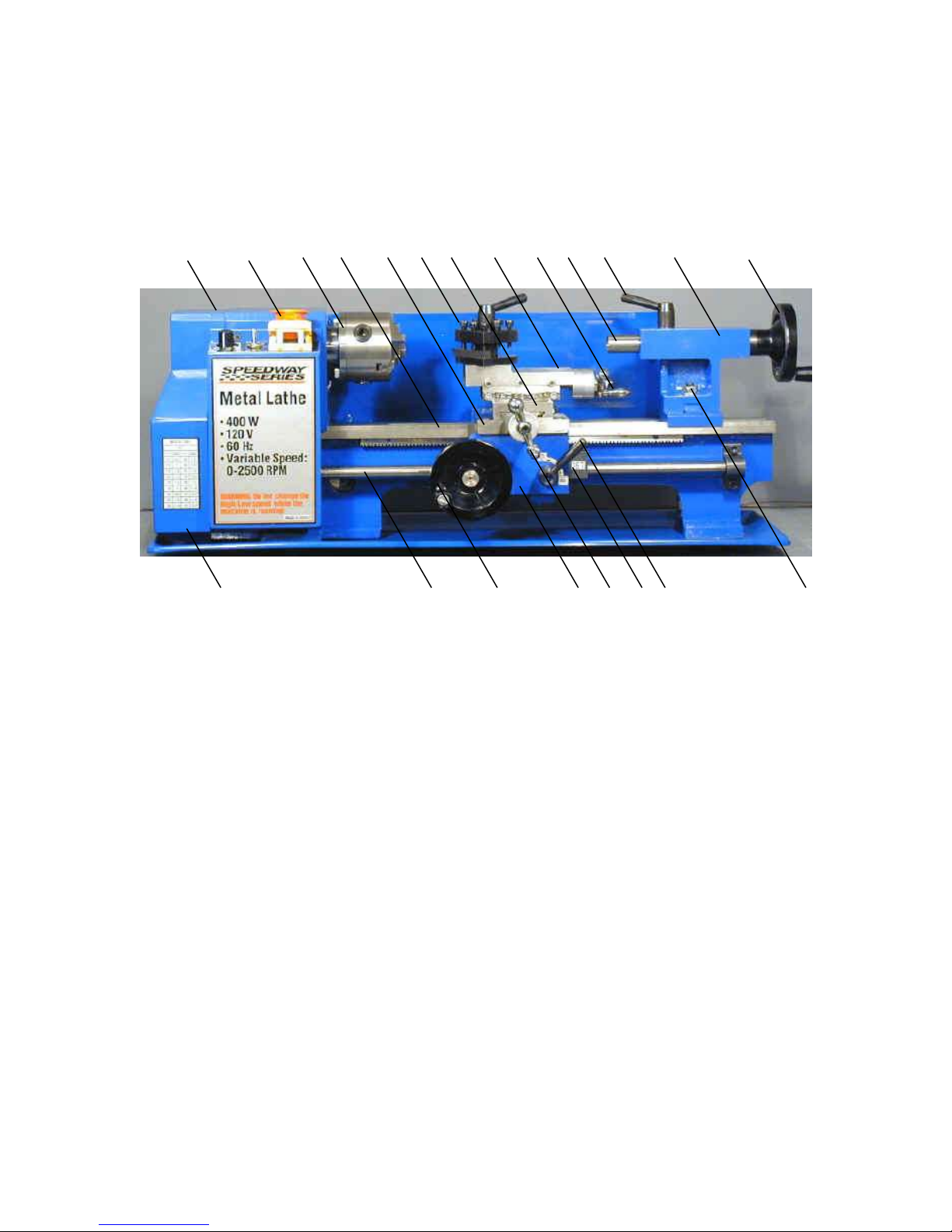
Features.....................................................................................6
Front View ...............................................................................6
Rear View ................................................................................7
Basic Accessories...........................................................................7
Cleaning .....................................................................................7
Mounting Your Lathe ......................................................................7
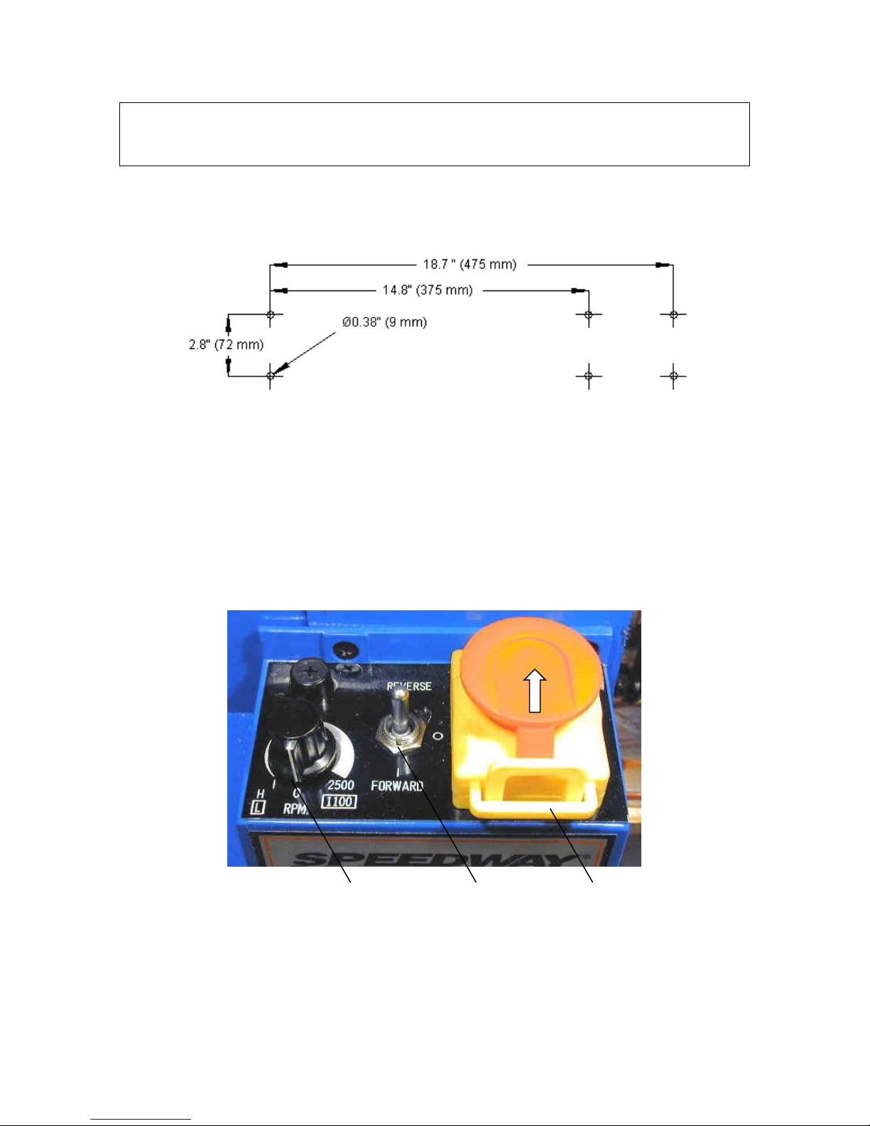
Operating Controls ........................................................................8
Motor Controls...........................................................................8
High/Low Speed Shifter ................................................................9
Power Feed Forward/Neutral/Reverse Lever ..................................... 10
Power Feed Lever ..................................................................... 10
Carriage Hand Wheel ................................................................. 10
Cross Slide Feed Handle.............................................................. 10
Compound Rest Feed Handle ........................................................ 11
Compound Rest Rotation............................................................. 11
Tailstock Lock Nut .................................................................... 11
Tailstock Quill Hand Wheel .......................................................... 11
Tailstock Quill Locking Lever........................................................ 11
Adjustments .............................................................................. 12
Carriage ................................................................................ 12
Cross Slide Gibs........................................................................ 12
Cross Slide Nut ........................................................................ 13
Compound Rest Gibs.................................................................. 13
Apron Position ......................................................................... 13
Half Nuts ............................................................................... 14
Lead Screw Mounting ................................................................. 14
Drive Belt............................................................................... 14
Lubrication................................................................................ 15
Lubricating the Transmission Gears ................................................ 17
Changing Chuck Jaws.................................................................... 17
Grinding Tool Bits........................................................................ 18
Grinding Tool Bits ..................................................................... 20
Grind the Front Relief ................................................................ 20

4
Grind the Left Side Relief............................................................ 20
Grind the Top Rake ................................................................... 20
Round the Nose........................................................................ 20
Adjusting Tool Bit Height ............................................................... 20
Turning .................................................................................... 21
Manual Turning ........................................................................ 21
Turning with Power Feed ............................................................ 22
Facing ..................................................................................... 22
Turning Angles ........................................................................... 23
Threading ................................................................................. 24
Change Gears .......................................................................... 24
Threading Dial ......................................................................... 27
Tool Bit ................................................................................. 28
Compound Angle ...................................................................... 28
Setting the Cutting Tool ............................................................. 29
Threading Process..................................................................... 30
Common Accessories .................................................................... 30
Cut-Off Tool Holder................................................................... 30
Quick Change Tool Post .............................................................. 31
Indexable Turning Tools.............................................................. 32
4-Jaw Chuck ........................................................................... 32
Faceplate............................................................................... 33
Centers and Dogs...................................................................... 33
Steady Rest and Follower Rest ...................................................... 34
Maintenance .............................................................................. 34
Cleaning ................................................................................ 35
Motor Brushes.......................................................................... 35

5
Introduction
This user’s guide covers the 7x10 and 7x12 mini lathes that are sold by
Grizzly Industrial, Harbor Freight Tools, Homier Mobile Merchants, Micro-Mark,
Northern Tool & Equipment, Enco, and Wholesale Tool.
These lathes are made in China, in several different factories, but to a similar
set of plans. The general operating principles covered in this document are
common to all of them.
Specifications
The following specifications are common to these lathes.
Metric Lathes
Inch Lathes
Swing over bed
180 mm
7”
Between Centers
200 mm / 300 mm
7.9” / 11.8”
Spindle Taper
3 Morse taper
3 Morse taper
Tailstock taper
2 Morse taper
2 Morse taper
Spindle Bore
20 mm
0.79”
Cross Slide Travel
65 mm
2.56”
Compound Rest Travel
55 mm
2.17”
Spindle Speed
100–2500 RPM
100–2500 RPM
Automatic Feed Rate
0.1 mm / Revolution
0.004”/ Revolution
Screw Threads
0.4–2.0 mm in 10 steps
12–52 TPI in 18 steps
Safety Considerations
Always use common sense when using a power tool. Review the safety
instructions that came with your lathe. Besides the general safety rules for any
power tool, the following are specific considerations for the mini lathe.
Your mini lathe is just that, a mini, or small lathe. Don’t attempt jobs that
are beyond its capacity.
Check the work piece after you place it in the chuck or other work holding
device. Be sure it is secure before turning on the lathe.
Don’t wear loose clothing or jewelry when operating the lathe.

6
Features
Front View
1. Headstock
2. Motor controls
3. 3-jaw chuck
4. Bed ways
5. Carriage
6. Tool post
7. Cross slide
8. Compound rest
9. Compound rest feed handle
10.Tailstock quill
11.Tailstock quill locking lever
12.Tailstock
13.Tailstock quill hand wheel
14.Change gear cover
15.Lead screw
16.Carriage hand wheel
17.Apron
18.Cross slide feed handle
19.Threading dial
20.Power feed lever
21.Tailstock lock nut
16
14
1
2
3
8
5
17
18
6
9
7
15
19
12
21
4
13
11
10
20

7
Rear View
1. High/low speed shifter
2. Power feed forward/neutral/reverse lever
Basic Accessories
The following accessories come with most mini lathes. Some mini lathes come
with additional accessories.
Chuck key for the 3-jaw chuck
Outside jaws for the 3-jaw chuck
Change gears: 30, 35, 40 (2), 45, 50, 55, 57, 60 and 65 teeth
Hex wrenches: 3, 4, 5, and 6 mm
Open end wrenches: 8 x 10 mm and 14 x 17 mm
Cleaning
Your lathe will arrive coated with grease to protect it from corrosion during
shipment. Follow this procedure to remove the grease:
1. Wipe most of the grease off with rags or paper towels.
2. Clean the surfaces with mineral spirits (paint thinner).
3. Coat the surfaces with oil.
See the lubrication section for specific recommendations for lubricants.
Mounting Your Lathe
All mini lathes come with rubber feet that attach to the same holes used to
secure the lathe for shipping. If you want your lathe to be portable, simply
install these feet.
2
1

8
Note: If your lathe didn’t come with them, adding chip tray braces
(LittleMachineShop.com part number 1328) spreads the feet by several inches
and makes the lathe much steadier.
You can also bolt your lathe to your workbench. The following diagram shows
the holes required. The wider bolt pattern is for the 7x12 lathe, while the
narrower bolt pattern is for the 7x10 lathe.
Mount the lathe to the workbench with 6 mm bolts. The bolts should be about
10 mm longer than the thickness of the workbench. Use fender washers on the
underside of wooden benches to prevent the bolt heads from pulling through.
Operating Controls
There are several controls used to operate the lathe. Become familiar with
them before you use the lathe.
Motor Controls
1. Speed control
2. Forward/off/reverse switch
3. Power switch
1
2
3

9
There are several versions of the control panel on the mini lathe, but they all
include the same controls. In some cases the power switch is a big red
“emergency” switch, and in some cases it is a rocker switch.
The big red emergency switch latches in the off position when you press the big
red button. To turn the switch on, slide the big red button in the direction of
the arrow. The big red button will swing up to the on position.
The power switch interrupts the input power to the speed control circuit
board.
The forward/off/reverse switch switches the polarity of the speed control
circuit board output power between the speed control circuit board and the
motor.
You control the motor speed by adjusting a potentiometer that provides the
speed setting value to the speed control circuit board. On some lathes there is
a safety switch on the speed control potentiometer that forces you to return
the control to minimum speed when starting the lathe.
CAUTION: Always turn the speed control to the minimum speed position before
starting the lathe. Starting the lathe with the speed control set to a higher
speed can damage the speed control circuit board.
To power up the lathe:
1. Turn the speed control to the minimum speed position.
2. Place the forward/off/reverse switch in the off position.
3. Turn on the power switch.
To start the lathe:
1. Ensure that the speed control is set to the minimum speed position.
2. Move the forward/off/reverse switch to the appropriate position.
3. Advance the speed control to the desired speed.
To stop the lathe:
1. Turn the speed control to the minimum speed position.
2. Move the forward/off/reverse switch to the off position.
3. If you want to power down the lathe, press the big red switch or the rocker
switch to turn off the power.
High/Low Speed Shifter
The high/low speed shifter is on the back of the headstock. It selects the
spindle speed range.
Low speed range
50*–1100 RPM
High speed range
50*–2500 RPM
* Minimum speed varies.

10
Never move this lever when the lathe is turning. You might need to turn the
spindle slightly by hand as you move the high/low speed shifter.
Power Feed Forward/Neutral/Reverse Lever
The power feed forward/neutral/reverse lever controls the direction of
rotation of the lead screw. When this lever is in the forward, or top, position
the lead screw moves the carriage toward the headstock. When this lever is in
the reverse, or bottom, position, the lead screw moves the carriage away from
the headstock. In the center, or neutral, position the lead screw is disengaged
and does not turn.
There is a strong spring in this lever. Pull out firmly on the end of the lever
while moving it.
NOTE: In many cases the detents for this control are not well formed, and in
some cases are not in the correct position. If your power feed will not stay
engaged, or if it does not disengage properly, inspect the detents in the back
of the headstock and move or enlarge them with a center punch.
Power Feed Lever
The power feed lever locks the half nuts around the lead screw, which engages
the power feed.
The power feed is engaged when this lever is down, and disengaged when this
lever is up.
Carriage Hand Wheel
The carriage hand wheel moves the carriage toward or away from the
headstock, depending on which way it is turned.
Use this hand wheel to position the carriage. Because this hand wheel moves
the carriage quickly it is not easy to use this hand wheel to move the carriage
while you are turning.
You cannot turn this hand wheel when the automatic feed is engaged.
Cross Slide Feed Handle
The cross slide feed handle moves the cross slide across the ways. Use this
handle to advance the tool into the work and for facing cuts.
The dial on this handle indicates the relative position of the cross slide. The
graduated dial can be repositioned for convenience.
On some lathes there are 40 divisions on the dial. On these lathes, each turn of
the handle advances the cross slide 1 mm or approximately 0.040”. The
distance is actually 0.03937”, an error of a little less than 2%.
Other lathes have 50 graduations on the dial. On these lathes, each turn of the
handle advances the cross slide 0.050”.

11
Compound Rest Feed Handle
The compound rest feed handle advances or retracts the compound rest. Use
this handle to advance the tool into the work.
The dial on this handle indicates the relative position of the cross slide. The
graduated dial can be repositioned for convenience.
On some lathes there are 40 divisions on the dial. On these lathes, each turn of
the handle advances the compound rest 1 mm or approximately 0.040”. The
distance is actually 0.03937”, an error of a little less than 2%.
Other lathes have 50 graduations on the dial. On these lathes, each turn of the
handle advances the compound rest 0.050”.
Compound Rest Rotation
The compound rest rotates on the cross slide and you can position it at any
angle.
Position the compound rest so it moves parallel to the ways to make precise
facing cuts.
Position the compound rest at 29.5 degrees for cutting standard threads.
To change the angle of the compound rest:
1. Using the compound rest feed handle, retract the compound rest until the
locking socket head cap screws are exposed.
2. Loosen the two socket head cap screws.
3. Turn the compound rest to the desired angle.
4. Tighten the two socket head cap screws.
NOTE: Use a protractor between the compound rest and the cross slide. Don’t
depend on the die cast or plastic protractor that’s on the side of the compound
rest on some lathes.
Tailstock Lock Nut
The tailstock is locked into position on the ways by the tailstock lock nut. Use a
15 mm wrench to tighten the tailstock lock nut.
Tailstock Quill Hand Wheel
The tailstock quill hand wheel moves the tailstock quill in and out. Most mini
lathes have rather poor graduations on the top of the quill that show how far it
is extended.
Retract the tailstock quill all the way to remove tools from the taper in the
tailstock quill.
Tailstock Quill Locking Lever
The tailstock quill locking lever keeps the tailstock quill from moving. Use the
tailstock quill locking lever to lock the tailstock quill in position when you are

12
turning between centers. Turn the lever clockwise to lock the tailstock quill,
and counterclockwise to unlock the tailstock quill.
Adjustments
Keeping your lathe in adjustment is an ongoing process. You should check all
the following adjustments when you set up your lathe and then periodically as
you use your lathe.
Carriage
The carriage is held on the ways by two adjustable retaining plates that are
bolted to the bottom of the carriage.
There are several fasteners in the carriage retainers. The socket head cap
screws are used to adjust the position of the retainers. The setscrews and lock
nuts lock the adjustments in place.
To adjust the carriage retainers:
1. Remove the right lead screw mounting bracket.
2. Disconnect the apron by removing the two socket head cap screws through
the front of the carriage.
3. Slide the apron to the right and off the lead screw.
4. Loosen all the fasteners on both retainers.
5. Snug the socket head cap screws so the carriage can move, but without
play.
6. Snug the setscrews. Do not over tighten or you might break the retainers.
7. While holding the setscrews from turning, tighten the lock nuts.
8. Replace the apron.
9. Replace the right lead screw mounting bracket.
Cross Slide Gibs
A gib is a strip of metal placed between the bearing surface of two machine
parts to ensure a precision fit and provide adjustment for wear. The mini lathe
has gibs in several places, including the cross slide.
To adjust the cross slide gibs:
1. Loosen the three lock nuts on the side of the cross slide.
2. Slightly loosen all three setscrews on the side of the cross slide.
3. Snug each setscrew equally. This will lock the cross slide in position.
4. Loosen each setscrew 1/8 turn to allow the cross slide to move.
5. While holding the setscrews from turning, tighten the lock nuts.
6. Test by turning the handle. Loosen or tighten all the setscrews the same
amount until the cross slide moves freely, but without play in the dovetail.

13
Cross Slide Nut
The cross slide nut is adjustable to remove free play from the cross slide feed
handle.
The three screws in the top of the cross slide adjust the cross slide nut.
The two outer screws tip the nut off horizontal to reduce the endplay in the
threads. The center screw locks the adjustment in place.
To adjust the cross slide nut:
1. Loosen all three screws.
2. Back the cross slide all the way away from the center of the lathe, until it
just contacts the dial.
3. Tighten the center screw until the feed handle becomes hard to turn.
4. Loosen the center screw until the feed handle just turns freely.
5. Tighten the near screw until the feed handle becomes hard to turn.
6. Loosen the near screw until the feed handle just turns freely.
7. Snug, but do not tighten the far screw.
Compound Rest Gibs
The compound rest also incorporates a gib for adjustment.
To adjust the compound rest gibs:
1. Loosen the three lock nuts on the side of the compound rest.
2. Slightly loosen all three setscrews on the side of the compound rest.
3. Snug each setscrew equally. This will lock the compound rest in position.
4. Loosen each setscrew 1/8 turn to allow the compound rest to move.
5. While holding the setscrews from turning, tighten the lock nuts.
6. Test by turning the handle. Loosen or tighten all the setscrews the same
amount until the compound rest moves freely, but without play in the
dovetail.
Apron Position
The apron is adjustable to center the half nuts horizontally on the lead screw.
To adjust the apron position:
1. Loosen the two socket head cap screws that secure the apron to the
carriage. They are at the front edge of the carriage.
2. Engage the half nuts on the lead screw.
3. Tighten the two socket head cap screws.

14
Half Nuts
There are two adjustments for the half nuts. The half nut gibs take the play
out of the half nuts. The half nut closing limit stops the half nuts from closing
too tightly on the lead screw.
To adjust the half nut gibs:
Tighten the three setscrews in the back edge of the apron to remove play
from the half nuts.
To adjust the half nut limit:
1. Loosen the lock nut on the bottom of the half nuts.
2. Adjust the setscrew until the half nuts close without binding on the lead
screw.
3. While holding the setscrew from turning, tighten the lock nut.
Lead Screw Mounting
The brackets that mount the lead screw can move slightly to ensure that the
lead screw does not bind in the half nuts.
To adjust the right lead screw mounting bracket:
1. Remove the tailstock by sliding it off the end of the ways.
2. Loosen the two mounting socket head cap screws on the right bracket.
3. Move the carriage as far to the right as possible.
4. Engage the half nuts on the lead screw.
5. Tighten the bracket mounting socket head cap screws.
6. Replace the tailstock.
To adjust the left lead screw mounting bracket:
1. Remove the change gear cover.
2. Loosen the locking nut on the change gear adjuster.
3. Loosen the two mounting socket head cap screws on the left lead screw
bracket.
4. Move the carriage as far to the left as possible.
5. Engage the half nuts on the lead screw.
6. Tighten the bracket mounting socket head cap screws.
7. Tighten the locking nut on the change gear adjuster.
8. Replace the change gear cover.
Drive Belt
The drive belt needs to be aligned correctly or it will wear on one side or the
other.

15
To adjust the drive belt:
1. Unplug the power cord.
2. Remove the motor cover from the back of the lathe.
3. Remove the change gear cover.
4. Remove the control box from the front of the lathe, but do not disconnect
any wires.
5. Loosen all the lock nuts on the front of the lathe.
6. Back off the top and bottom set screws a couple turns.
7. Make sure that nothing will get into the change gear drive.
8. Make sure the control box is in a safe but accessible position.
9. Plug in the power cord.
10.Reach around to the back of the lathe and hold the motor.
11. Turn the motor on at slow speed.
12.While the motor is running, move the motor to a position where the belt has
sufficient tension and does not rub either side of the pulley.
13.Tighten the nuts on the two studs that are aligned horizontally.
14.Snug the setscrews that are aligned vertically.
15.Turn off the motor.
16.Tighten the lock nuts.
17.Replace the control box.
18.Replace the change gear cover.
19.Replace the motor cover.
Lubrication
We recommend the use of two lubricants on your lathe.
Where oil is required, we recommend Mobil 1 synthetic motor oil. Mobil 1
far exceeds the lubrication needs of the mini lathe, and maintains a good
surface film between applications.
Where grease is required, we recommend Lubriplate 630-AA lithium (white)
grease. Lithium grease is a plastic-friendly grease that is easy to find and
easy to use.

16
The following points on your lathe require lubrication.
Location
Lubricant
Frequency
Notes
Lathe ways
Oil
Daily
Apply oil to both the front and back
ways on both sides of the carriage.
Move the carriage back and forth to
spread the oil.
Lead screw
threads
Oil
Daily
Clean swarf (chips, shavings, and
debris) daily.
Compound rest
dovetail
Oil
Daily
Advance the compound rest to the
extent of its normal travel. Apply
oil to the end of the gib and the
ends of the dovetails. Retract the
compound rest.
Cross slide
dovetail
Oil
Daily
Advance the cross slide to the
extent of its travel. Apply oil to the
end of the gib and the ends of the
dovetails. Retract the cross slide.
Lead screw
bushings
Oil
Weekly
There is an oil fitting on the top of
each one. Remove the change gear
cover to lubricate the left bushing.
Other machined
surfaces
Oil
Weekly
Oil lubricates and prevents
corrosion.
Chuck
Oil
Monthly
Disassemble, clean and lubricate.
Wrap with a paper towel, secure
with an elastic band, and run lathe
to sling out excess oil.
Cross slide feed
screw
Grease
Yearly
Compound rest
feed screw
Grease
Yearly
Lead screw
drive gears and
bushings
Grease
Yearly
Also lube change gears as you use
them.
Transmission
gears
Grease
Yearly
See procedure below for lubricating
the transmission gears without
removing the headstock.
Carriage hand
wheel drive
gears
Grease
Yearly

17
Location
Lubricant
Frequency
Notes
Tailstock quill
and screw
Grease
Yearly
The spindle and countershaft bearings are deep groove ball bearings that are
shielded and do not require additional lubrication.
Lubricating the Transmission Gears
You can lubricate the transmission gears without removing the headstock by
using a spray can of lithium grease.
To lubricate the transmission gears:
1. Unplug the power cord.
2. Remove the control box from the front of the lathe, but do not disconnect
any wires.
3. Remove the screw or screws holding the ground wires to the front of the
headstock.
4. Insert the lithium grease can’s spray tube into one of the open holes.
5. Spray the grease while rotating the chuck by hand.
6. Shift the high/low speed shifter to the opposite position.
7. Spray the grease while rotating the chuck by hand.
8. Reconnect the ground wires.
9. Replace the control box.
10.Plug in the power cord.
Changing Chuck Jaws
3-Jaw lathe chucks come with two sets of jaws.
The “normal” set is called the inside jaws,
because the stepped side is designed to fit
inside of hollow work pieces and hold by an
outward force. In many cases, however,
these jaws are used to clamp on the outside
of smaller objects using the long straight
side.

18
The second set of jaws is called the outside
jaws because the stepped side of these jaws
is designed to clamp on the outside of
larger objects.
Because of the construction of a 3-jaw chuck, each of the three jaws in a set is
different. You will find a number in the groove in the side of each jaw that
identifies its position in the set.
To install a set of chuck jaws:
1. Place the three jaws in numeric order on the bench.
2. Slide jaw number 1 into the slot in the chuck that has the serial number
stamped in it.
3. Press the jaw into the slot with one hand, and with the other hand, turn the
chuck key to open the chuck.
4. You will feel the jaw move out in the slot as you turn. Stop turning right
after the jaw clicks inward in the slot.
5. Turn the chuck key to close the chuck about ¼ turn to engage jaw 1.
6. Slide jaw 2 into the next slot counterclockwise from jaw 1 when you are
looking toward the headstock.
7. Slide jaw 3 into the open slot.
8. While pressing jaws 2 and 3 into the slots, turn the chuck key to close the
chuck.
Grinding Tool Bits
When you purchase a new lathe tool bit, it might have an angle on the end, but
it is not properly sharpened for turning. Grinding lathe tool bits is a bit of an
art. It takes some practice to get good at it.
You need to create a cutting edge that is sharp, extends out so that the cutting
edge and not the side of the tool contacts the work, but that still has enough
support to maintain sufficient strength to cut metal.
Before diving in, there are some terms you need to understand. The illustration
below shows these terms.
First, notice that there are two cutting edges on the tool bit. There is a cutting
edge on the end of the tool bit called the front cutting edge. There is also a

19
cutting edge on the side of the tool. Between these cutting edges is a rounded
section of cutting edge called the nose.
Side Cutting Edge
The side cutting edge does most of the cutting. As the too
bit moves along the work piece the side cutting edge
removes most of the material.
Front Cutting Edge
The front cutting edge cuts when the tool is advanced into
the work.
Nose
The nose is a critical part of the cutting edge, because it
produces the surface finish of the work piece.
Side Rake
The side rake produces the side cutting edge that cuts into
the work piece.
Side Relief
Side relief provides clearance for the side cutting edge.
Without side relief, the side of the tool bit would hit the
work piece and not allow the cutting edge to penetrate
the work piece.
Back Rake
The back rake produces the front cutting edge that cuts
into the work piece.

20
Front Relief
Front relieve provides clearance for the front cutting
edge. Without front relief, the front of the tool bit would
hit the work piece and not allow the cutting edge to
penetrate the work piece.
How to Grind Tool Bits
Use a bench grinder to sharpen your tool bits. Even an inexpensive bench
grinder can do a good job grinding lathe tool bits. In some cases, you might
want to purchase a higher quality fine grit wheel.
Keep a small cup of water near your grinder. Grinding generates heat, which
can cause two problems. The tool bit will become too hot to hold. Overheating
can also affect the heat treatment of the tool bit, leaving the cutting edge
soft.
Use a protractor to measure the angles. They are not super-critical, but you
should try to stay within one degree of the recommendations.
Grind the Front Relief
The first step in creating a tool bit is to grind the front relief. For most work, a
relief angle of 10° works well.
While you are grinding the front relief, you are also creating the front cutting
edge angle. Make this angle about 10° also, so that the corner formed by the
front cutting edge and the side cutting edge is less than 90°.
Grind the Left Side Relief
Form the left side relief next. Again, create about a 10° angle. You don’t need
to form a side cutting angle. The side cutting edge can be parallel to the side
of the tool blank.
Grind the Top Rake
The top of the tool bit is ground at an angle that combines the back rake and
the side rake. The side rake is most important, because the side cutting edge
does most of the work. For cutting steel and aluminum, the side rake should be
about 12° and the back rake should be about 8°. For cutting brass, the rake
angles should be much less, or even 0°.
Round the Nose
A small nose radius allows you to turn into tight corners. A large nose radius
produces better surface finishes. Create a nose radius that is appropriate for
the tool bit you are creating.
Adjusting Tool Bit Height
The cutting edge of the tool bit should almost always be set to the center
height of the lathe spindle.
Table of contents
Other Little Machine Shop Lathe manuals
Popular Lathe manuals by other brands

GRS
GRS 003-615 manual

Sharp
Sharp 1118H Operations manual & parts list

Precision matthews
Precision matthews PM-1440-2SM manual

Central Machinery
Central Machinery CENTRAL MACHINERY 45861 Set up and operating instructions

The Cool Tool
The Cool Tool UNIMAT 1 Classic Instructions for use

Tryax
Tryax TY30-VS Operation manual

Draper
Draper WTL330 instructions

Parkside
Parkside 337006 2004 Operating and safety instructions

Clarke
Clarke CWL460 Operation & maintenance instructions

Bench Power Tools
Bench Power Tools ML10001 owner's manual

Grizzly
Grizzly G0657/G0658 owner's manual

Axminster
Axminster SIEG Model Engineer Series Original instructions