Littlebits STEAM STUDENT SET User manual

DOWNLOAD THE
TEACHER'S GUIDE
and other classroom
resources at
littleBits.cc/student-set
STEAM
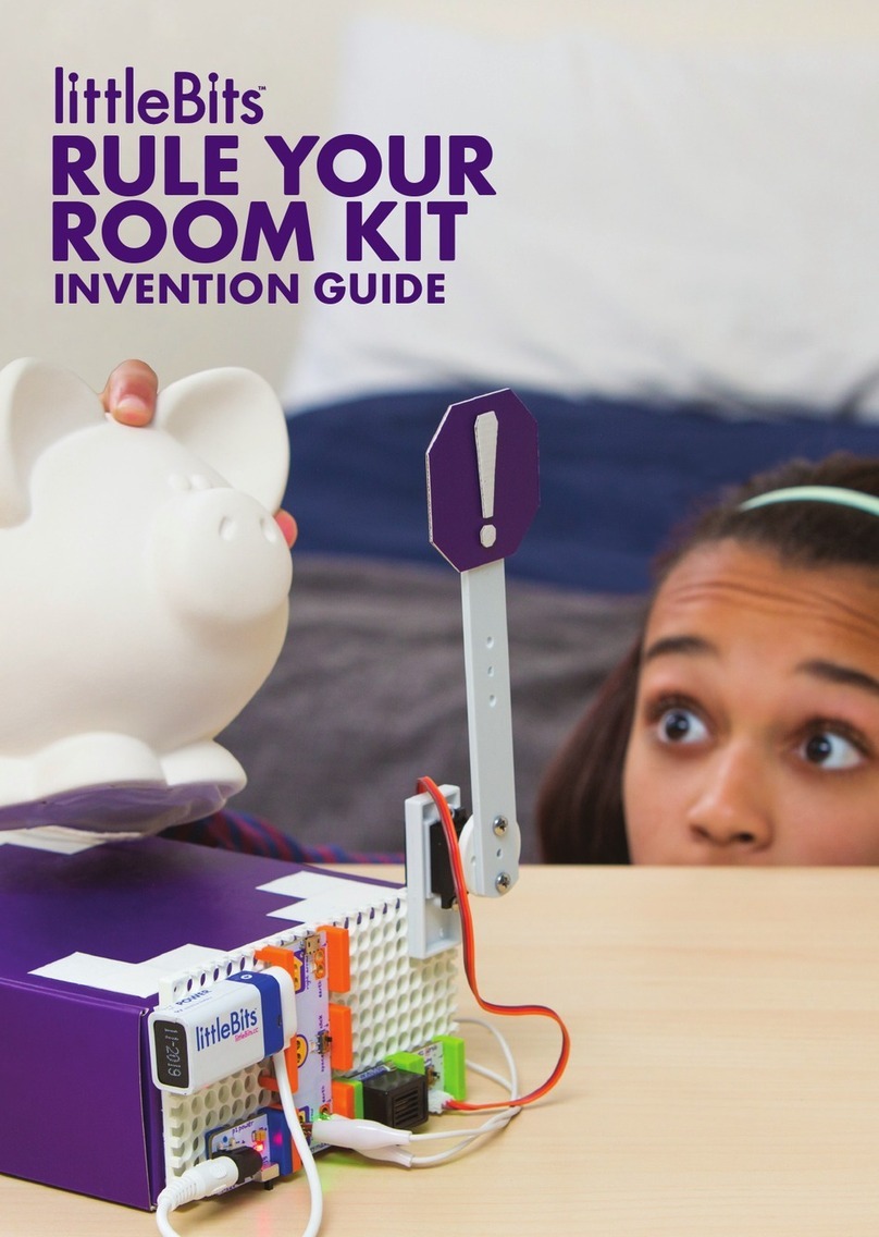
STUDENT SET
INVENTION GUIDE


littleBits Basics
BITTM INDEX
POWER
INPUT
WIRE
OUTPUT
ACCESSORIES
Inventing
with littleBits
Trouble-
shooting
Tips
Continue
Your Inventor
Journey
GUIDED CHALLENGES
Guided challenges start with instructions
for a simple invention. Once you've
created the invention, the challenge moves
into the Remix phase where creativity
really takes o.
Invent a Self-Driving Vehicle
Invent an Art Machine
Invent a Throwing Arm
Invent a Security Device
OPEN CHALLENGES
Open challenges get you to flex your creative
muscles. These challenges start with an
open-ended problem. Your mission is to
explore ways you could use littleBits to create
an invention that solves that problem.
Hack Your Classroom
Invent for Good
Invent a Chain Reaction Contraption
Hack Your Habits
04
06–27
07
09
14
17
24
28
71
72
32–58
32
39
46
53
59–70
59
62
65
68
STEAM
STUDENT SET PG 32 PG 39 PG 46 PG 53
TEACHER'S GUIDE and other
classroom resources available
at littleBits.cc/student-set.
SHARE & DISCOVER inventions
on the littleBits Invent App or
online at littleBits.cc/invention.
STEAM is the evolution of STEM education,
adding Art to Science, Technology, Engineer-
ing, and Math. Students gain technical skills
by exploring creative, collaborative solutions
to real-world problems.
The challenges in the littleBits STEAM Student
Set link to NGSS (Next Generation Science
Standards) Engineering Design standards.
INVENTION GUIDE

2
WE INVENT THE
WORLD WE
WANT TO LIVE IN.

3
WE INVENT THE
WORLD WE
WANT TO LIVE IN.

ANATOMY OF A BITTM
Learn how you can tell top from bottom.
1
BIT FEET
BOTTOM
TOP
BITSNAPS
(“X” ICONS)
OPEN HARDWARE SYMBOL
& LITTLEBITS LOGO
COLOR-CODED BY FUNCTION
BitsTM are grouped into four dierent categories,
which are color-coded.
Learn more about your Bits in the BIT INDEX ON PG 06
2
POWER (BLUE)
Power Bits, plus a power
supply, run power through
your circuit.
INPUT (PINK)
Input Bits accept input from
you or the environment and
send signals that aect the
Bits that follow.
OUTPUT (GREEN)
Output Bits do something –
light up, buzz, move…
WIRE (ORANGE)
Wire Bits connect to other
systems and let you build
circuits in new directions.
BUILD DIRECTION
BASICS
BUILD & PLAY
WITH THIS
CIRCUIT FIRST
i3 button
BIT NAME

5
Learn more about your Bits in the BIT INDEX ON PG 06
MAGNET MAGIC!
Bits snap together with magnets. The magnets are
always right – you can’t snap them together the
wrong way.
3
ARROWS SHOULD POINT IN THE SAME DIRECTION
IF THE BITS WON’T SNAP TOGETHER, TRY SPINNING
ONE AROUND AND MAKE SURE THE ARROWS POINT
IN THE SAME DIRECTION
ORDER IS IMPORTANT
POWER BITS always come rst and INPUT BITS
only aect the OUTPUT BITS that come after them.
4
WITH NO OUTPUT BIT AFTER IT, THE INPUT BIT HAS NOWHERE
TO SEND ITS SIGNAL
THE INPUT BIT AFFECTS THE OUTPUT BITS THAT FOLLOW
SOME BITS ARE ADJUSTABLE
Switches, buttons, and dials on the board allow
you to change how the Bit functions.
5
FLIP THE SWITCH TO CHANGE MODES
ADJUST SENSITIVITY WITH
PURPLE SCREWDRIVER

6
BITTM INDEX
p1 power
p3 USB power
i3 button
i5 slide dimmer
i12 temperature
sensor
i13 light sensor
i16 pulse
w1 wire
w7 fork
w10 inverter
o2 long LED
o3 RGB LED
o6 buzzer
o11 servo
o13 fan
o21 number
o25 DC motor
a5 magnet shoes
a6 hook & loop shoes
a9 mounting board
a10 motorMate
a14 USB power adapter
a19 servo hub
a23 mechanical arm
a24 servo mount
a25 wheel
07
08
POWER INPUT WIRE OUTPUT ACCESSORIES
09
10
11
12
13
14
15
16
17
18
19
20
21
22
23
24
25
26
27
Occasionally BitsTM get updated, so the features or appearance
of your Bits may dier from those used in this guide.

7
MEET THE BIT
HOW IT WORKS
p1 POWER
Every circuit starts with power. It provides the electricity that
makes your Bits spin, buzz, blink, and shine.
The power Bit converts the
9 volts of electricity in the
battery to the 5 volts that
littleBits circuits run on.
The power Bit also sends a
signal through your circuit.
Controlling this signal with
inputs is how you control
your circuit.
REAL WORLD ANALOGIES
PHONE CHARGER
o2 LONG LED
p1 POWER
MODE: on/o
On light
SAMPLE CIRCUIT

8
MEET THE BIT
HOW IT WORKS
p3 USB POWER
The USB power may be the smallest in the series, but it's big
enough to send electricity to all your creations. This Bit lets
you power your circuit through a micro USB cable. It can be
connected to a computer or wall adapter for non-stop power.
Like the power Bit, the USB
power Bit sends a 5 volt
signal through your circuit,
which allows you to control
your Bits.
Instructions for the projects
in this Kit use the p1 power
Bit, but you can use the USB
power for all of them as well.
PHONE CHARGER
REAL WORLD ANALOGIES
o3 RGB LED
p3 USB POWER
On light
SAMPLE CIRCUIT

9
MEET THE BIT
MINI-CHALLENGE
i3 BUTTON
The button Bit is a classic: big, round, and springy for
comfortable pressing! Push it to turn something on and
release it to turn it o .
Can you invent a chair that makes noise when you sit down?
The button is like a door.
When you press it, the door
opens, letting the signal
pass through the Bit and on
to the next Bits in the circuit.
The button is a momentary
switch, you must continue
to press it for the signal to
flow. When you release
the button, the door closes,
stopping the signal from
passing on to other Bits.
VIDEO GAME CONTROLLER ELEVATOR BUTTON GAME SHOW BUZZER
p1 POWER
i3 BUTTON
o13 FAN
REAL WORLD ANALOGIES
SAMPLE CIRCUIT HOW IT WORKS

10
MEET THE BIT
MINI-CHALLENGE
i5 SLIDE DIMMER
Slide this dimmer back and forth to control your circuit.
As you slide it up, more signal goes to the Bits that follow,
brightening lights, speeding up motors, and raising the
volume on your buzzer.
Can you invent something with the slide dimmer that waves
a flag back and forth? How could you change the speed it
waves?
When the slider is all the
way to the left, it’s sending
an o or 0 volt signal.
When the slider is all the
way to the right, it’s sending
a 5 volt signal. The slider
can be positioned to send
any signal between 0 and
5 volts.
HOUSEHOLD
DIMMER SWITCH STEREO VOLUME CONTROL CAR PEDAL
p1 POWER
i5 SLIDE DIMMER
o2 LONG LED
REAL WORLD ANALOGIES
SAMPLE CIRCUIT HOW IT WORKS

11
MEET THE BIT
MINI-CHALLENGE
With the temperature sensor you can use the temperature
in the surrounding air to control your circuit. It's especially
useful for gathering data when paired with the number Bit
set to VALUE mode.
Can you invent a temperature-controlled gadget to beat the
summer heat?
The temperature sensor takes
a measurement from the
environment and translates it
into a signal. The higher the
temperature it senses, the
more signal it sends out to
the following Bits (making
lights brighter and motors
turn faster).
THERMOSTAT MEDICAL THERMOMETER AUTOMATIC TEA KETTLE
i12 TEMPERATURE SENSOR
p1 POWER
o21 NUMBER
MODE:
VALU E
MODE: F° or C°
This is the component that
measures the temperature.
i12 TEMPERATURE SENSOR
A
t
e
m
p
e
r
a
t
u
r
e
s
e
¡
n
s
o
r
t
l
s
y
o
u
r
a
u
t
o
m
a
c
t
t
l
e
w
n
t
o
t
u
r
n
o
f
f
.
021 number:
count down
021 number:
read value
REAL WORLD ANALOGIES
SAMPLE CIRCUIT HOW IT WORKS

12
MEET THE BIT
MINI-CHALLENGE
i13 LIGHT SENSOR
Use this Bit to control your circuits with light! The amount
of light shining on the sensor will change how your circuit
behaves. It's a great way to activate your circuit without
hands and is perfect for alarms!
Can you invent something that moves when the lights go out?
The light sensor measures
how much light is shining
on it. It has two modes.
In LIGHT mode, as the
light shining on the sensor
gets brighter, more signal
passes through it (making
lights brighter or motors
turn faster). In DARK mode,
the signal increases as it
gets darker.
Use the purple screwdriver to
turn the dial and adjust how
much light it takes to change
the signal. Clockwise
increases sensitivity, counter-
clockwise decreases it.
NIGHT LIGHT SENSOR PHOTOGRAPHER'S
LIGHT METER FINGER PULSE METER
p1 POWER
o21 NUMBER
MODE:
VALU E
A
p
u
l
s
e
m
e
r
s
n
e
s
a
b
r
i
g
h
t
l
i
g
h
t
i
n
t
o
y
o
u
r
fi
e
r
d
u
s
e
s
a
l
i
g
h
t
s
s
o
r
t
o
m
e
a
s
u
r
e
b
l
o
o
d
f
l
o
w
.
021 number:
count down
021 number:
read value
MODE: light or dark
SENSITIVITY: "–" decrease,
"+" increase
This is the component that
measures light.
i13 LIGHT SENSOR
REAL WORLD ANALOGIES
SAMPLE CIRCUIT HOW IT WORKS

13
i16 PULSE
The pulse is like a heartbeat that makes the Bits after it turn on
and o in a steady rhythm.
POLICE SIREN FIREFLY CLOCK SECONDHANDTURN SIGNAL
The pulse is a switch that
opens and closes over
and over again. When it's
open, the signal from the
previous Bit passes through
to the next Bit. When the
switch closes, the signal
is blocked.
Use the purple screwdriver
to adjust the dial. You can
change the speed of the
rhythm by turning the small
dial on the Bit with your
purple screwdriver.
o2 LONG LED
p1 POWER
MEET THE BIT
MINI-CHALLENGE
Can you invent a warning signal with the pulse? How can
you make the signal pulse faster or slower?
i16 PULSE
SPEED: "–" decrease,
"+" increase
REAL WORLD ANALOGIES
SAMPLE CIRCUIT HOW IT WORKS

14
MEET THE BIT
w1 WIRE
The wire Bit has a flexible wire running between its two
bitSnaps. This allows you to place your Bits farther apart, turn
corners, and make connections that can twist, turn, and spin.
The wire doesn’t change the
signal in any way – it just
carries it over from one Bit
to another.
EXTENSION CORD POWER LINES STRING OF LIGHTS
p1 POWER
w1 WIRE
o3 RGB LED
MINI-CHALLENGE
Can you invent a circuit that uses the wire to shine the RGB
LED on the light sensor?
REAL WORLD ANALOGIES
SAMPLE CIRCUIT HOW IT WORKS

15
MEET THE BIT
w7 FORK
The fork gives you more options for connecting your Bits;
it lets you connect a single Bit to as many as three others.
If you place an input before the fork, it will control all three
outputs at once, such as light, sound, and motion.
The fork takes the incoming
signal and sends it to all
three output bitSnaps.
POWER STRIP FORK IN THE ROAD
p1 POWER
w7 FORK
o3 RGB LED
o21 NUMBER
o6 BUZZER
MINI-CHALLENGE
Can you invent a circuit where an input controls three outputs?
REAL WORLD ANALOGIES
SAMPLE CIRCUIT HOW IT WORKS

16
MEET THE BIT
w10 INVERTER
The inverter is an example of a logic Bit. It sends out the
opposite of whatever it receives: send it an on signal,
and the inverter changes it to an o ff signal, or vice versa.
Would you like a button that turns things o ff instead of on?
Try the inverter.
Anytime the inverter receives
a signal lower than 50%
power (2.5 volts) the inverter
sends full power (5 volts) to
the next Bit in the circuit.
If the inverter receives a sig-
nal greater than 2.5 volts,
the inverter sends 0 volts to
the next Bit in the circuit.
OPPOSITE DAY ALTERNATING
POLICE LIGHTS
p1 POWER
i3 BUTTON
w10 INVERTER
o3 RGB LED
MINI-CHALLENGE
Can you invent something with the inverter that alerts you if
someone takes a book o the table?
T
i
s
:
p
o
w
e
r
,
p
u
l
s
e
,
l
i
g
h
t
,
i
n
r
t
e
r
,
l
i
g
h
t
.
REAL WORLD ANALOGIES
SAMPLE CIRCUIT HOW IT WORKS

17
MEET THE BIT
o2 LONG LED
The long LED is a flexible lighting option. We call it the
“long” LED because the light is connected to the board by a
cable, which lets you put the light in some interesting places.
This Bit uses a light-emmiting
diode (LED) to turn electricity
into light. The more signal
you send the Bit, the brighter
the light shines.
FLASHLIGHT STREET LAMP ANGLERFISH
p1 POWER
i3 BUTTON
o2 LONG LED
MINI-CHALLENGE
Can you invent a new wearable accessory using the
long LED?
REAL WORLD ANALOGIES
SAMPLE CIRCUIT HOW IT WORKS

18
MEET THE BIT
o3 RGB LED
The RGB LED is a light with adjustable color. You can use
the purple screwdriver to turn the dials and create your own
custom color mix of red, green, and blue.
The RGB LED is actually
three very small lights (a
red, a blue, and a green
light). Turning the dials
changes the brightness of
each light. The colors from
these lights mix together
to create every color in
the rainbow.
TRAFFIC LIGHT DECORATIVE LIGHTSJUMBOTRON
p1 POWER
i5 SLIDE DIMMER
MINI-CHALLENGE
Can you invent a flashlight that uses your favorite color?
o
u
s
d
s
o
f
R
G
B
L
E
D
s
c
r
e
a
t
e
s
e
d
i
s
p
l
a
y
s
o3 RGB LED
R: Adjust the amount of red light
G: Adjust the amount of green light
B: Adjust the amount of blue light
REAL WORLD ANALOGIES
SAMPLE CIRCUIT HOW IT WORKS
Table of contents
Other Littlebits Toy manuals