TEST YOUR
CIRCUIT
Now build the WIRELESS RECEIVER CIRCUIT. This will be the buzzer in your room. Press on
hook & loop shoes to keep your circuit together.
Cut pieces of the hook & loop strip and stick them to the place you want your doorbell to
hang. Attach the TRANSMITTER CIRCUIT to the strips, and place the receiver inside your
room USING THE SAME METHOD. Stick your battery to the wall with Glue Dots.
REMIX
STUFF
GUARD
PRIVACY, PLEASE! Keep your parents’ or
siblings’ grubby fi ngers out of your stuff
by setting up a wireless alarm system. By
installing the light sensor (transmitter circuit)
in your drawer, you’ll know that someone
is looking through your stuff when your
buzzer goes off on your receiver circuit.
MATERIALS
• drawer or secret compartment
• mounting board
WIRELESS
DOORBELL
2
3
21
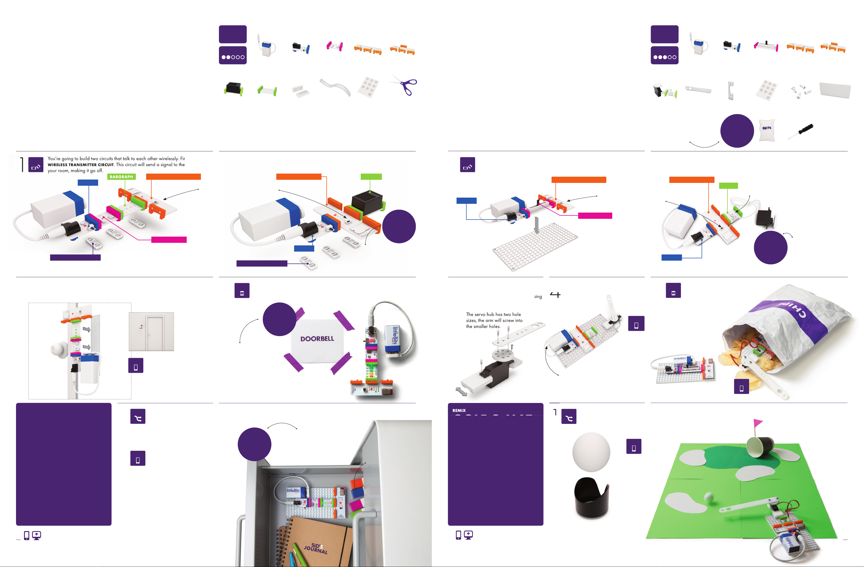
You’re going to build two circuits that talk to each other wirelessly. First build your
WIRELESS TRANSMITTER CIRCUIT. This circuit will send a signal to the buzzer in
your room, making it go off .
SET UP YOUR ALARM.
CREATE AN INVENTION THAT KEEPS PEOPLE FROM BURSTING INTO YOUR PRIVATE SPACE! Your
new doorbell will alert you when someone wishes to enter by sending a wireless signal from
outside the door to the buzzer inside your room. Could you use this system to communicate secret
messages without your parents knowing? Show us how you’re using the wireless doorbell on our
community pages.
TIME
20 min
LEVEL
w22 wireless
transmitter
p1 power (×2)battery & cable (×2)
o6 buzzer o9 bargraph a6 hook & loop
shoes (×6)
i13 light sensor
scissors*
*from around
the house
1
GUESTS CAN NOW ANNOUNCE THEIR ARRIVAL BY COVERING THE LIGHT
SENSOR TO "PRESS" THE DOORBELL. Try adjusting the sensitivity on the light sensor
and see if you can get it to detect the shadow of anyone approaching your room.4
Turn on the power for both
your circuits and cover
the light sensor with your
hand. It should buzz.
TROUBLESHOOTING PG 20
BARGRAPH
w22 wireless
transmitter
i5 slide dimmerp1 power (×2)battery & cable (×2)
a9 mounting board
(×2)
o11 servo & hub mechanical arm servo mount
BUILD YOUR PRANK ARM. On the
receiver circuit, assemble the servo
mount, hub, and mechanical arm using
a Phillips-head screwdriver.
REMIX
GOLF-O-MAT
You can use your Mischief Machine for
all kinds of fun – NOT JUST PRANKS! We
found it’s great for playing mini golf. Build
your golf course using some colored paper
and a paper cup. Can you cook up any
other ways to use your mechanical arm?
MATERIALS
• ball from caster
• bottle cap
• paper cup
NICE TO HAVE
• colored paper
• toothpick (fl ag)
MISCHIEF
MACHINE
1
2
3
2
You’re going to build two circuits that talk to each other wirelessly. First build your
WIRELESS TRANSMITTER CIRCUIT, which will work as your remote controller, send-
ing its signal to the mechanical arm. Then press it onto a mounting board.
Remove the ball from the ball
caster. This is now your golf
ball!
PLAY GOLF! Line up your new golf putter and swing away wirelessly.
CREATE AN INVENTION TO MAKE YOUR PARENTS SHRIEK, EEK! A pair of wireless Bits™and a
servo help you pull this prank on unsuspecting friends and family while you watch it all go down.
Wirelessly control the mechanical arm to rustle whatever you put it into – is it a mouse or a mon-
ster? Who knows! Just hope they don’t prank you back.
TIME
20 min
LEVEL
Phillips-head
screwdriver* *from around
the house
1
PRESS YOUR RECEIVER CIRCUIT ONTO
A MOUNTING BOARD.
4 5
Build the second circuit. This will be the WIRELESS RECEIVER CIRCUIT that will rustle your bag.
Use Glue Dots to stick the bat-
teries onto the mounting board.
The servo hub has two hole
sizes, the arm will screw into
the smaller holes.
HIDE THE ENTIRE RECEIVER CIRCUIT INSIDE A CHIP BAG and place it wherever
your unsuspecting victim will fi nd it. Quickly slide the dimmer back and forth
when you’re ready to scare the daylights out of them!
Turn on the power for both
your circuits and move the
slide dimmer to see how it
wirelessly controls the servo.
TROUBLESHOOTING PG 20
TEST YOUR
CIRCUIT
CUSTOMIZE: WHERE ELSE CAN YOU
HIDE THE MISCHIEF MACHINE?
Could you stick it in a drawer or
under your brother’s bed?
LITTLEBITS.CC/GGKIT & THE APP
COMMUNITY CHALLENGE: Create a
full, 18-HOLE COURSE with diff erent
obstacles and terrain. Mix it up!
What would a golf course look like in
the desert or the Arctic? Share your
landscapes with the community, and
check out what others have done.
COMMUNITY CHALLENGE:
Create a SECRET LANGUAGE
made of buzzes. Share your lan-
guage on our community pages.
LITTLEBITS.CC/GGKIT & THE APP
CUSTOMIZE: This wireless
alarm can be installed any-
where that’s dark, so why not
an entire room? EXPERIMENT
WITH DIFFERENT SPACES and
light sensor sensitivities. Know
when someone walks into a
room and turns on a light.
COMMUNITY CHALLENGE: HOW LOUD CAN
YOU MAKE SOMEONE SCREAM? TAKE A VIDEO
of your personalized prank and share it on the
community page!
Create a sign telling people to
put their hand over the light sen-
sor to announce their arrival.
INSIDEOUTSIDE
PRO
TIP
Opening the drawer should set
off your buzzer, even if your
receiver circuit is on the opposite
end of your house. Busted!
TROUBLESHOOTING PG 20
mount, hub, and mechanical arm using
ADJUST YOUR INVENTION.
Switch the light sensor’s
mode to LIGHT and turn the
SENSITIVITY DIAL ALL THE WAY
CLOCKWISE. Any hint of light
will now trigger an alarm!
w21 wireless
reciever w21 wireless
reciever
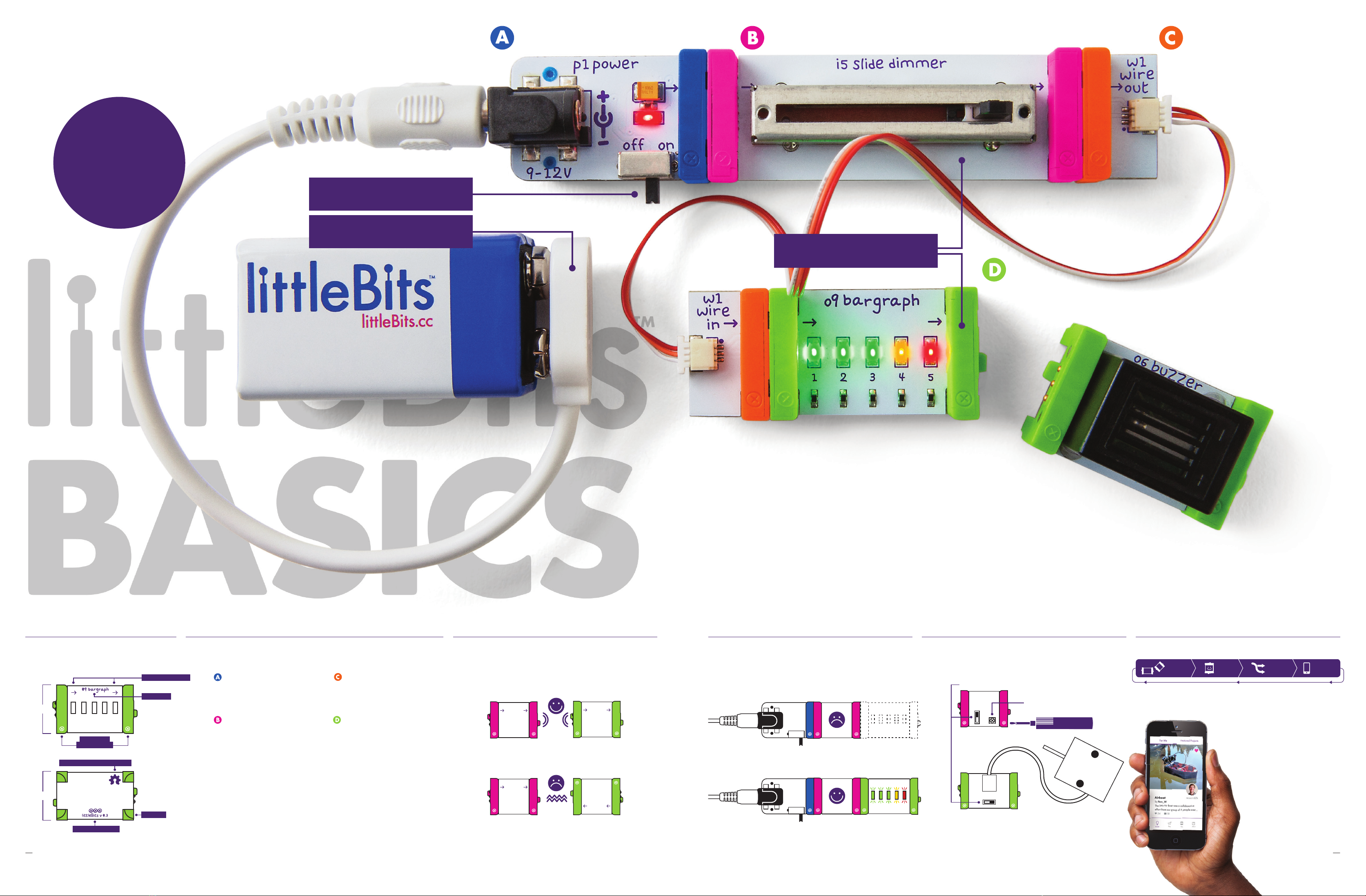
POWER
You’re going to build two circuits that talk to each other wirelessly. First build your
WIRELESS TRANSMITTER CIRCUIT
. This circuit will send a signal to the buzzer in
your room, making it go off .
WIRELESS TRANSMITTER
POWER
WIRELESS RECEIVER BUZZER
TEST YOUR
CIRCUIT
WIRELESS TRANSMITTER
POWER
LIGHT SENSOR
Set the mode to DARK and
turn the sensitivity dial ALL THE
WAY CLOCKWISE using your
purple screwdriver.
LEARN MORE PG 20
SLIDE DIMMER
Make sure the wireless receiver is on
the SAME CHANNEL (a,b,c,d, or e) as
your transmitter.
PAIRING TIP PG 20
Make sure the wireless receiver is
on the SAME CHANNEL (a,b,c,d, or e)
as your transmitter.
PAIRING TIP PG 20
SERVO
Glue Dots®
POWER
HOOK & LOOP SHOES
HOOK & LOOP SHOES
Press on hook & loop shoes to
keep your circuit together.
screws (×4)
The servo hub has two hole
sizes, the arm will screw into
non-metallic
bag/container*
Use a chip bag with a
non-metallic fi nish. Metallic
fi nishes may interfere with
wireless signals, derailing
your prank.
PRO TIP
hook & loop strip Glue Dots®
INVENTION 04 INVENTION 05
Set your servo to TURN mode
to control how and when your
mechanical arm moves.
LEARN MORE PG 21
WIRELESS RECEIVER
SHARE AT
LITTLEBITS.CC/GGKIT
SHARE AT
LITTLEBITS.CC/GGKIT
REMIX REMIX
SHARE
SHARE
SHARE
SHARE
SHARE
PLAY PLAY
CREATE CREATE
h
o
l
e
i
n
o
n
e
!
8 9