LittleMachineShop.com HiTorque 7500 User manual

The premier source of tooling, parts, and accessories for bench top machinists.
HiTorque 8½×20 Bench Lathe User’s Guide
Model 7500 •Model 7550 Deluxe
from LittleMachineShop.com

2
© Copyright 2022 LittleMachineShop.com.
All rights reserved.
Written by Chris Wood of LittleMachineShop.com
Revision 3, October 2022
LittleMachineShop.com
https://www.littlemachineshop.com
396 W. Washington Blvd. #500, Pasadena, CA 91103
info@littlemachineshop.com•(800) 981-9663

Contents
Introduction .......................................4
Specifications......................................4
Safety Considerations ............................5
General Safety .................................5
Lathe Safety ....................................5
Electrical Safety ...............................5
Machine Safety .................................6
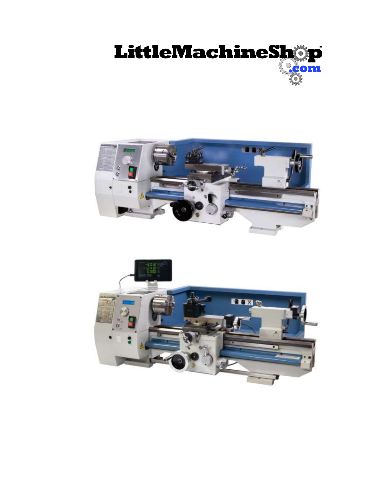
Features ............................................7
Front View ......................................7
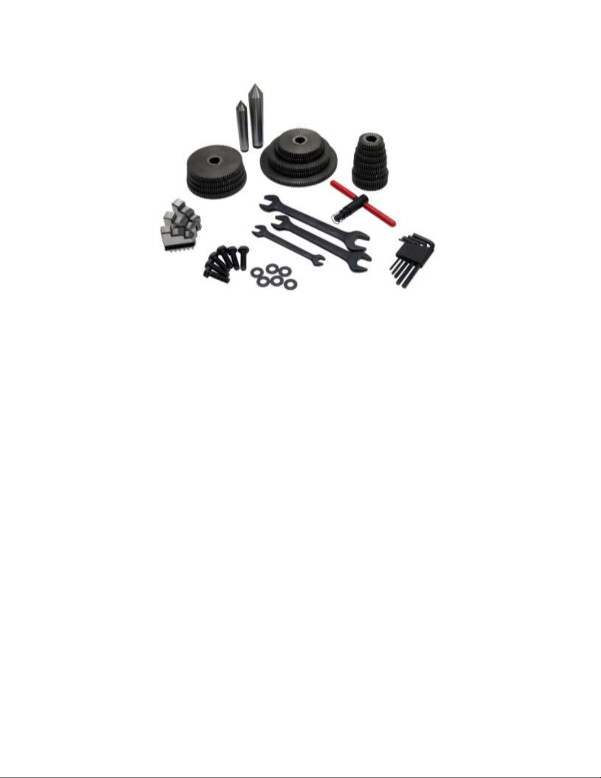
Accessories.........................................8
Cleaning ............................................8
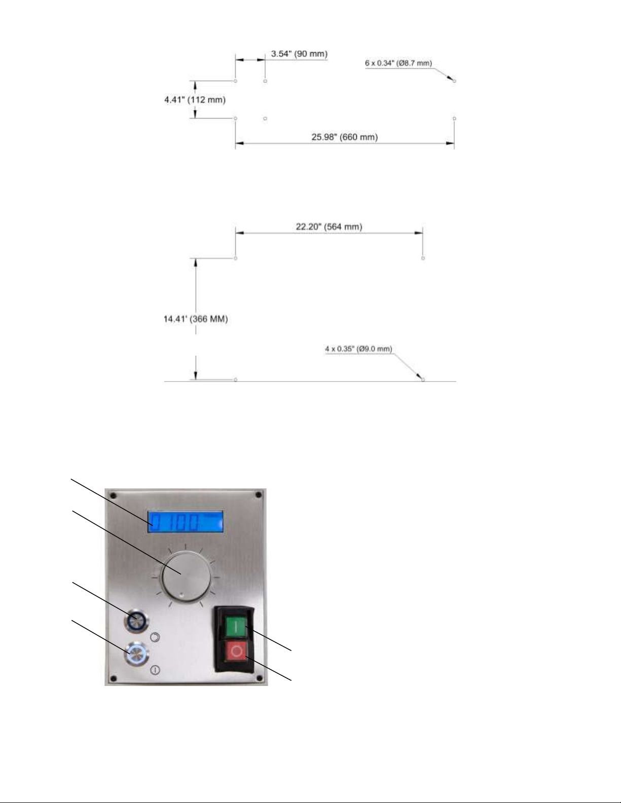
Mounting Your Lathe .............................8
Lathe Controls.....................................9
Motor Controls..................................9
Carriage and Cross Feed Controls ......... 10
Tailstock Controls............................ 13
Bluetooth DRO (Model 7550 only) ............ 14
Using the app ................................. 15
Axis detail settings .......................... 15
Absolute versus incremental coordinates 16
Points and workspaces ...................... 16
Tools ........................................... 17
Adjustments ..................................... 17
Carriage ....................................... 17
Cross Slide Gib ............................... 18
Cross Slide Nut ............................... 19
Compound Rest Gib.......................... 19
Compound Rest Nut ......................... 19
Apron Position ................................ 19
Tailstock Position ............................ 20
Half Nuts ...................................... 21
Drive Belt ..................................... 21
Maintenance ..................................... 22
Cleaning ....................................... 22
Lubrication.................................... 22
Chuck ............................................. 23
Changing Chuck Jaws........................ 23
Mounting Work in a 3-Jaw Chuck.......... 24
Tool Bits.......................................... 24
Grinding Tool Bits............................ 25
Adjusting Tool Bit Height ................... 26
Turning ........................................... 27
Manual Turning............................... 27
Turning with Power Feed................... 27
Facing ............................................ 28
Facing with Power Feed .................... 28
Turning Angles .................................. 29
Threading ........................................ 29
Change Gears................................. 30
Change Gear Tables ......................... 32
Making Left Hand Threads.................. 33
Tool Bit ........................................ 33
Compound Angle ............................. 34
Setting the Cutting Tool .................... 34
Threading Process ........................... 35
Common Accessories ........................... 35
Quick Change Tool Post..................... 36
Indexable Turning Tools .................... 36
4-Jaw Chuck .................................. 37
Faceplate ..................................... 37
Live and Dead Centers ...................... 38
Steady Rest and Follower Rest ............ 38
Parts Diagram: 7500............................ 40
Parts Diagram: 7550............................ 42
Parts List ......................................... 44
Wiring Diagram.................................. 47

4
Introduction
This user’s guide covers care and operation of the LittleMachineShop.com HiTorque 8½×20 Bench
Lathe. Be sure to read and understand the safety guidelines presented in this book before using
your lathe.
The HiTorque 8½×20 Bench Lathe is available in two models:
•Model 7500 is the standard version.
•Model 7550 is the deluxe version. It includes all the features of Model 7500 and adds:
oDigital position readouts (DRO) on the carriage, cross slide, compound rest, and
tailstock
oQuick change tool post set (QCTP) with five tool holders
oCompound rest modified to better accommodate the QCTP
oAnodized aluminum hand wheels and chrome knobs and levers
oFull length heavy duty splash guard
Chris’ Tip: You can upgrade your Model 7500 lathe with the following items available from
LittleMachineShop.com:
•Part number 5497: Digital position readout (carriage, cross slide, and compound rest)
•Part number 5513: Android tablet display
•Part number 5880: Digital position readout (tailstock)
•Part number 2280: Quick change tool post set, AXA
•Part number 4914: Compound rest top (required for AXA QCTP)
•Part numbers 4162, 4165, 2104, 2145: Chrome hand wheels and handles
Installation of these components creates a machine that functions like a Model 7550 deluxe lathe,
although it will have some cosmetic differences.
Specifications
Swing over bed
8.5" (215 mm)
Swing over
saddle
4.6" (118 mm)
Distance
between centers
20" (510 mm)
Cross slide travel
3.9" (100 mm)
Compound rest
travel
2.8" (70 mm)
Spindle through
hole
0.8" (20 mm)
Spindle taper
#3 Morse taper
Tailstock taper
#2 Morse taper
Spindle speed
100–2000 RPM
Range of threads
3–100 TPI; 0.25–5.0 mm
Longitudinal
power feed rates
0.0018" (0.045
mm)/revolution
0.0049" (0.126
mm)/revolution
Cross slide power
feed rates
0.0007" (0.019
mm)/revolution
0.0019" (0.048
mm)/revolution
Power
requirements
120 V 60 Hz 12 Amps
Spindle motor
output
1.34 hp (1000 Watts)
Machine weight
220 lbs (100 kg)
Overall
dimensions
40" x 22" x 16" (1010
mm x 550 mm x 400
mm)

5
Safety Considerations
Always use common sense when using a power tool. Besides the general safety rules for any power
tool, following also are specific considerations for the bench lathe.
General Safety
•Use common sense. Think through the results of your actions before you act.
•Understand the operation of the machine. Do not operate the machine if you do not know
what is going to happen.
•Learn, don’t experiment. Study, understand, and do things where you have a clear
expectation of the outcome. Don’t “see what will happen.”
•You are responsible for your own actions. We can’t be held responsible for your actions when
you use the machine.
Lathe Safety
•Your bench lathe is a small lathe. Don’t attempt jobs that are beyond its capacity.
•Check the work piece after you place it in the chuck or other work holding device. Be sure it is
secure before turning on the lathe.
•Don’t wear loose clothing or jewelry when operating the lathe.
•Stop the spindle and make sure the machine is in a safe condition before:
oOpening or removing safety shields
oReaching into work area
oChanging or adjusting tools
oChanging or adjusting work pieces
oChanging speed ranges
oClearing chips or coolant
•Inspect cutting tools for sharpness, chips, and cracks before each use. Replace dull, chipped,
or cracked cutting tools immediately.
•Handle cutting tools with care. Cutting edges are very sharp and can cause lacerations.
•Do not use unbalanced work pieces or fixtures in the spindle
•Remove all tools (wrenches, chuck keys, locking pins, and so on) from the spindle immediately
after using them.
Electrical Safety
•Plug the machine into a grounded receptacle.
•Ensure that all components are properly grounded. The easiest way to ensure this is to plug
your machines and devices into grounded outlets that you have tested.
•Use caution when using liquids and electricity. Ensure that coolants and lubricants are kept
away from high voltage electrical components.
•Disconnect all components from the power receptacle before servicing.
•In the event of a power outage, turn off all components to ensure that the machine does not
restart unexpectedly.

6
Machine Safety
•Keep bystanders, children, and visitors a safe distance away while operating any power tool.
•Read the manual. Know the operation of every control before you attempt any operation of
the machine.
•Make sure that all guards are in place and functioning before operating the machine.
•Check for damage and abnormal wear before operating the machine.
•Always wear safety glasses (side shields are recommended) that are ANSI Z87.1-2003
compliant.
•Wear hearing protection (ear plugs or ear muffs) when operating loud machines.
•Wear appropriate clothing; no rings, gloves, neckties, jewelry, or loose-fitting garments. Bind
long hair or wear a hat.
•Do not use compressed air for cleaning machines. A shop vacuum works well and is much safer.
•Don’t operate machinery while under the influence of drugs or alcohol.
•Ensure that your machines are well lit. Ensure that your shop is well lit and have additional
task lighting where appropriate.
•Maintain a clean and uncluttered work area.
•Avoid pinch points.
•Never leave a running machine unattended.
•Do not force or overload machinery.
•Use appropriate cutting tools with appropriate feeds and speed.
•Cutting tools get hot during use and can cause burns if handled inappropriately.
•Do not attempt to use work pieces that are too large or two heavy for the machine.
•Maintain your machines. Ensure that it is well-adjusted and in a safe state.
•Clear chips with a brush or other tool, never with your hands or with compressed air.
•Make sure the machine is on a flat, level surface that can support the weight of the machine
plus fixtures, vise, and work piece.
•Clamp work securely. Cutting forces are significant and can turn work pieces that are not
secured into projectiles.
•Be aware that chips and dust from some materials (magnesium, for example) are flammable.
Understand the materials you are using.

7
Features
Front View
1. Motor controls (for details, see “Motor
Controls” on page 9)
2. Headstock
3. Chuck
4. Carriage
5. Cross slide
6. Tool post
7. Compound rest
8. Tailstock (for details, see “Tailstock
Controls” on page 13)
9. Change gear cover
10. Bed ways
11. Apron (for details, see “Carriage and
Cross Feed Controls” on page 10)
12. Lead screw
1
2
3
4
5
6
7
8
9
10
11
12

8
Accessories
The following accessories come with the HiTorque Bench Lathe.
•#2 Morse taper dead center
•#3 Morse taper dead center
•Change gears (for details, see
“Threading” on page 29)
•Outside jaws for the 3-jaw chuck (for
details, see “Changing Chuck Jaws” on
page 23)
•Chuck key for the 3-jaw chuck
•Open end wrenches: 8 x 10 mm, 14 x 17
mm, and 17 x 19 mm
•Hex wrenches: 2.5, 3, 4, 5, and 6 mm
•Mounting bolts and washers
Cleaning
Your lathe will arrive coated with grease to protect it from corrosion during shipment. Follow this
procedure to remove the grease:
1. Wipe most of the grease off with rags or paper towels.
2. Clean the surfaces with mineral spirits (paint thinner).
3. Coat the surfaces with oil.
See “Lubrication”on page 22 for specific recommendations for lubricants.
Mounting Your Lathe
Many people purchase a stand or chip tray for the HiTorque Bench Lathe. The machine bolts right
to these with the cap screws that are furnished. You might need to unbolt the motor to install the
two bolts on the back of the headstock.
You can also bolt your lathe to your workbench. The following diagram shows the holes required.

9
Mount the lathe to the workbench with M8 (or 5/16") bolts. Use fender washers on the underside
of wooden benches to prevent the bolt heads from pulling through. You might need to unbolt the
motor to install the two bolts on the back of the headstock.
If you have the chip tray, its mounting dimensions are shown below.
Lathe Controls
Become familiar with the controls used to operate the lathe before you use the lathe.
Motor Controls
1. Power switch
2. Emergency stop (E-stop) switch
3. Start/stop button
4. Spindle direction button
5. Speed control knob
6. Spindle speed readout
6
5
4
3
1
2
14.41" (366 mm)

10
Power Switch and Emergency Stop (E-stop) Switch
The green power switch enables input power to the speed control circuit board. The red E-stop
switch disconnects the power.
Turn the power off when you are not using the lathe.
Start/Stop Button
The Start/Stop button illuminates and starts the spindle when pressed while the power is on. The
spindle runs at the last set speed. Press the button again to stop the spindle. Use this button for
normal operation of the lathe.
Spindle Direction Button
The spindle direction button controls the direction the spindle turns. After turning on the power
and pressing Start, the spindle turns in the forward direction—the direction used for normal
turning. Press the button to toggle between forward and reverse directions. The button
illuminates to indicate reverse direction.
You can change the motor direction at any time and at any speed that safety allows. The motor
will make a controlled change of direction.
Speed Control Knob
The speed control knob adjusts the spindle speed.
Spindle Speed Readout
The spindle speed readout shows the speed of the spindle in revolutions per minute (RPM). It also
indicates the direction of turning, forward or reverse.
Using the Motor Controls
Use the motor controls to turn the spindle.
To power up the lathe:
•Press the top half of the power switch. The spindle speed readout illuminates.
To start the lathe:
1. Press the start/stop button. The button illuminates and the spindle turns.
2. If you want the spindle to turn in the other direction, press the spindle direction button.
3. Use the speed control knob to adjust the spindle speed.
To stop the lathe:
•Press the start/stop button. The lathe retains the speed and direction settings so that the next
time you start the lathe, it resumes at the same speed and direction.
To stop the lathe in an emergency:
•Press the red E-stop button.
Carriage and Cross Feed Controls
You can power the carriage, you can power the cross feed, and you can thread with the HiTorque
Bench Lathe.

11
1. Carriage hand wheel
2. Cross slide feed handle
3. Compound rest feed handle
4. Carriage lock screw
5. Half nut lever
6. Power feed lever
Carriage Hand Wheel
The carriage hand wheel moves the carriage toward or away from the headstock, depending on
which way it is turned.
Use this hand wheel to position the carriage. Because this hand wheel moves the carriage quickly
it is not easy to use this hand wheel to move the carriage while you are turning.
Pull the hand wheel towards you to disengage it when you are using power feed.
Carriage Lock Screw
Use a 4-mm hex wrench to tighten the carriage lock screw when you want to prevent the carriage
from moving.
Cross Slide Feed Handle
The cross slide feed handle moves the cross slide in and out. Use this handle to advance the tool
into the work and for facing cuts.
The dial on this handle indicates the relative position of the cross slide. The graduated dial can be
repositioned for convenience.
There are 50 divisions on the dial. Each turn of the handle advances the cross slide 0.050".
3
1
2
5
6
4
Carriage lock
screw

12
Compound Rest Feed Handle
The compound rest feed handle advances or retracts the compound rest. Use this handle to
advance the tool into the work.
The dial on this handle indicates the relative position of the compound rest. The graduated dial
can be repositioned for convenience.
There are 50 divisions on the dial. Each turn of the handle advances the cross slide 0.050".
Digital Position Readout (Model 7550 only)
The HiTorque Deluxe Bench Lathe has a digital readout on the compound rest.
To use the digital readout:
The readout is easy to use. There are two buttons: ON/OFF and mm/inch.
Button
Function
ON/OFF
Press to turn on the display.
While the display is on, press to set the display to zero at the current position.
Press and hold to turn off the display. Doing so extends battery life. (The display
shuts off automatically after about 30 minutes of nonuse.)
mm/inch
Switches the display between millimeters and inches.
Chris’ Tip: These digital readouts do not account for backlash in the feed screw. Always take your
readings when you are turning the screw in the same direction. This is not a problem on a lathe,
because a single cut will only be made in one direction—in for turning, and out for boring.
To replace the battery:
Each DRO uses a single CR2032 lithium battery (LittleMachineShop.com part number 4292).
1. On the bottom of the display unit, squeeze together the two tabs and then pull out the
battery drawer.
2. Replace the battery and then slide the drawer in until it snaps shut.
Compound Rest Rotation
The compound rest rotates on the cross slide and you can position it at any angle.
Position the compound rest so it moves parallel to the ways to make precise facing cuts.
Position the compound rest at 29.5 degrees for cutting standard threads.
To change the angle of the compound rest:
1. Loosen the two socket head cap screws along the sides of the compound rest.
2. Turn the compound rest to the desired angle.
Chris’Tip: You may need to remove one of the compound rest hold-down nuts to turn the
compound past it.

13
3. Tighten the two socket head cap screws.
Chris’Tip: For accurate work, use a protractor between the compound rest and the cross slide.
Don’t depend on the markings on the side of the compound rest.
Half Nut Lever
The half nut lever locks the half nuts around the lead screw, which engages the carriage drive for
threading.
The half nuts are engaged when this lever is to the right and disengaged when this lever is to the
left.
CAUTION: Do not engage the half nuts for any turning or facing operation.
Chris’Tip: Don’t try to engage the half nuts when the power feed is engaged. There’s an
interlock, but you can break it if you try.
You’ll find it easier to engage or disengage the half nuts while the lathe is running. If you do
attempt to change when the lathe is stopped, don’t force it.
Power Feed Lever
The power feed lever engages the carriage drive when it is down, and the cross slide drive when it
is up. Power feed is disengaged in the middle position. Push the lever to the left before moving it
up or down.
Chris’Tip: Don’t try to engage the power feed when the half nuts are engaged. There’s an
interlock, but you can break it if you try.
You’ll find it easier to engage or disengage the power feed while the lathe is running. If you do
attempt to change when the lathe is stopped, don’t force it.
Tailstock Controls
Use the tailstock for turning between centers.
Tailstock Locking Lever
The tailstock is locked into position on the ways by the tailstock locking lever on the back of the
tailstock. Pull the lever toward you to tighten the tailstock lock. Push the lever back to release
the tailstock.
Tailstock Quill Hand Wheel
The tailstock quill hand wheel moves the tailstock quill in and out. There are (mm) graduations on
the top of the quill that show how far it is extended. There are 0.001" graduations on the hand
wheel dial.
Retract the tailstock quill all the way to remove tools from the taper in the tailstock quill.
Tailstock Quill Digital Position Readout (Model 7550 only)
The HiTorque Deluxe Bench Lathe has a digital readout on the tailstock that displays the quill
position more precisely than the graduated markings on the standard model. Operation of the
tailstock readout is the same as those for the compound rest. See “Digital Position Readout (Model
7550 only)” on page 12.

14
Tailstock Quill Locking Lever
The tailstock quill locking lever keeps the tailstock quill from moving. Use the tailstock quill
locking lever to lock the tailstock quill in position when you are turning between centers. Turn the
lever clockwise to lock the tailstock quill, and counterclockwise to unlock the tailstock quill.
Bluetooth DRO (Model 7550 only)
The Android tablet included with your DRO has the SIEG DRO app preinstalled. To begin using it,
you must pair the tablet to the DRO scales, and you must configure the app, as described in the
following sections.
To pair the devices
1. Be sure the lathe is plugged in so that the Bluetooth transceiver in the lathe has power.
2. Use the furnished USB cable to plug the tablet into the back of the lathe. (This connection is
only for power, so if it’s more convenient to plug the tablet into another USB port or power
receptacle, that’s fine.)
Then, on the Android tablet:
3. Turn on the power and swipe up to unlock it.
4. Open Settings. (If you don’t see a Settings icon near the center of the screen, open the app
drawer—the middle icon of the quick launch bar on the bottom or right edge of the screen.)
5. In Settings, tap Bluetooth under Wireless & Networks.
6. Tap Search For Devices in the upper right corner of the screen.
7. Tap HC-06 when it appears under Available Devices.
8. Enter the PIN 1234 and tap OK.
The devices are now paired.
Chris’ Tip: If you’re using a single display device for multiple DROs, you can change the name
from HC-06 to give each machine a unique name. Tap a name under Paired Devices, edit the
name, and tap OK.
To configure the app:
1. Start the SIEG DRO app.
2. If it appears in the upper-right corner of the screen, tap Connect to select the correct
Bluetooth device. Tap HC-06 to select the lathe.
3. The vertical ellipsis in the upper right corner of the screen is a menu. Tap it and select
Settings.
4. Here is where you tell the app about your machine. Verify the following settings.
•Machine type: Lathe
•Under X Axis
•Axis CPI: 5080
•Invert Readout: check
•Under Y Axis
•Enable Y Axis: remove check
•Under Z Axis
•Axis CPI: 5080

15
•Under W Axis
•Enable W Axis: remove check
5. Tap the Back button at the bottom of the screen when you have made the settings.
Using the app
Your DRO should now be working. Turn a hand wheel and watch the numbers change. By
convention, the axis parallel to the spindle (that is, the axis on which the carriage moves) is the Z
axis, and the cross slide moves along the X axis.
The axis readouts appear at the left top of the screen.
The buttons across the bottom affect all axes.
The abs/incr button to the right of each axis readout affects only that axis.
The right side of the screen has a list of saved points and a list of saved tools.
Chooses inch or mm display
Sets the workspace origin to the current position of the machine
Selects Absolute coordinates or Incremental coordinates for all axes
Sets tool offsets
For the X-axis, switches between measuring radius or diameter
Axis detail settings
Tap one of the axis position values to see the Axis Details.

16
Tap the Position value to enter the current position value.
Tap to set the incremental value to zero.
Hold to set both the absolute value and the incremental value to zero.
Turns on an audible warning that you are approaching a defined point.
Absolute versus incremental coordinates
The DRO keeps track of two coordinate systems: absolute and incremental.
Absolute coordinates are the overall coordinates of your work piece. Select an edge of the
workpiece and set the axes to 0.000.
Incremental coordinates are used when you want to work on a feature, such as a groove, that
exists on your work piece. You can, for example, set an incremental 0 position at one edge of the
groove, and then use incremental values to machine the groove.
Points and workspaces
Points are a set of coordinates that define a spot on your work piece. Workspaces keep track of
points that you have recorded. The right side of the display window shows a list of recorded
points.
To save a point:
•Any time you are at a location you want to save, tap Add Point. A point with the current
coordinates is added to the list.
To go to a point:
•Tap the point in the list. The display changes to show how far from the point you are. Simply
move the carriage and cross slide until the Z- and Y- positions read zero and you are at the
point.
•To de-select a point, tap it again.

17
To preview a workspace
•Once you have a collection of points, you can get an idea if they are correct by previewing the
workspace. Tap the vertical ellipsis menu to the right of the workspace name. Choose Preview
Workspace to see the relationship of the points.
Tools
The DRO can keep track of your tool dimensions. This is useful if your tools maintain their X-axis
position between uses, such as when you use a quick change tool post to hold your turning tools.
Replacing a tool like this will return it to the same X-axis position.
You can enter the values for the current tool using the Tool Offsets button. Enter the values and
tap Set Tool Offset. While a tool offset is in effect, the position readouts are shown in red to
alert you to this fact.
To clear the current tool offset, press and hold the Tool Offset button.
Predefined tools
To add a tool:
1. Tap the vertical ellipsis menu in the upper right corner. Select Add Tool.
2. Name your tool and add the values for that tool.
3. Tap Save to add the tool to the list of tools.
To select a tool:
•To choose a tool and use the predefined offset, simply tap the tool in the list of predefined
tools. (Tap Tools on the right side of the screen to see the list.) The Tool Offset window
appears. You can adjust any values you need for this job and tap Set Tool Offset. These
changes are not saved with the tool.
•Alternatively, tap the Tool Offsets button and select the tool from the Tools list. Then tap Set
Tool Offset.
To modify or delete a tool:
•Tap and hold the tool’s name in the list of predefined tools. Then tap Edit Tool or Delete
Tool.
Adjustments
Keeping your lathe in adjustment is an ongoing process. You should check all the following
adjustments when you set up your lathe and then periodically as you use your lathe. Looseness in
the carriage retaining plates or the gibs can cause chatter when you are using the lathe. If you
experience chatter, check all these adjustments.
Carriage
The carriage is held on the ways by retainers with gibs that are bolted to the bottom of the
carriage.
A gib is a strip of metal placed between the bearing surface of two machine parts to ensure a
precision fit and provide adjustment for wear. The bench lathe has gibs in several places,
including the carriage.

18
To adjust the carriage gibs:
1. Loosen the three socket head cap screws on the back bottom of the carriage.
2. Loosen the four lock nuts on the back bottom of the carriage.
3. Slightly loosen all four set screws.
4. Snug each cap screw equally. This will lock the carriage in position.
5. Loosen each cap screw about 1/8 turn to allow carriage to move, but without play.
6. Snug the set screws to lock the cap screws in position. Do not over tighten.
7. While holding the set screws from turning, tighten the lock nuts.
8. Test by moving the carriage. Loosen or tighten all the cap screws the same amount until the
carriage moves freely, but without play on the ways.
Cross Slide Gib
Carriage retainer
Cross slide gib adjusters
Compound rest gib adjusters

19
To adjust the cross slide gib:
1. Loosen the three lock nuts on the side of the cross slide.
2. Slightly loosen all three set screws on the side of the cross slide.
3. Snug each set screw equally. This will lock the cross slide in position.
4. Loosen each set screw 1/8 turn to allow the cross slide to move.
5. While holding the set screws from turning, tighten the lock nuts.
6. Test by turning the handle. Loosen or tighten all the set screws the same amount until the
cross slide moves freely, but without play in the dovetail.
Cross Slide Nut
The cross slide nut is adjustable to remove free play from the cross slide feed screw.
The cross slide nut is partially split and set screws adjust the gap to allow adjustment of play in
the nut.
To adjust the cross slide nut:
1. Move the cross slide as far back as it will go. The screw disengages.
2. Engage the nut and move the cross slide back toward you enough that the nut is fully engaged.
3. Adjust the set screws in the cross slide nut to remove play without making it hard to turn.
Compound Rest Gib
The compound rest also incorporates a gib for adjustment.
To adjust the compound rest gib:
1. Loosen the four lock nuts on the side of the compound rest.
2. Slightly loosen all four set screws on the side of the compound rest.
3. Snug each set screw equally. This will lock the compound rest in position.
4. Loosen each set screw 1/8 turn to allow the compound rest to move.
5. While holding the set screws from turning, tighten the lock nuts.
6. Test by turning the handle. Loosen or tighten all the set screws the same amount until the
compound rest moves freely, but without play in the dovetail.
Compound Rest Nut
The compound rest nut is adjustable to remove free play from the compound rest feed screw.
The compound rest nut is partially split and set screws adjust the gap to allow adjustment of play
in the nut.
To adjust the compound rest nut:
1. Remove the compound rest by removing the two socket head cap screws that lock it from
rotating.
2. Turn the compound rest over to access the adjustable nut.
3. Adjust the cap screw in the cross slide nut to remove play without making it hard to turn.
4. Replace the compound rest and the two socket head cap screws.
Apron Position
The apron is adjustable to center the half nuts horizontally on the lead screw.

20
To adjust the apron position:
1. Loosen the four socket head cap screws that secure the apron to the carriage. There are two
on the left side of the carriage and two on the right side of the carriage
2. Engage the half nuts on the lead screw.
3. Tighten the four socket head cap screws.
Tailstock Position
The tailstock is adjustable from front to rear so you can align it with the spindle.
Tailstock
adjustment
set screw
Tailstock locking
set screw
Apron bolts
This manual suits for next models
1
Table of contents
Other LittleMachineShop.com Lathe manuals