livn 5963000 User manual
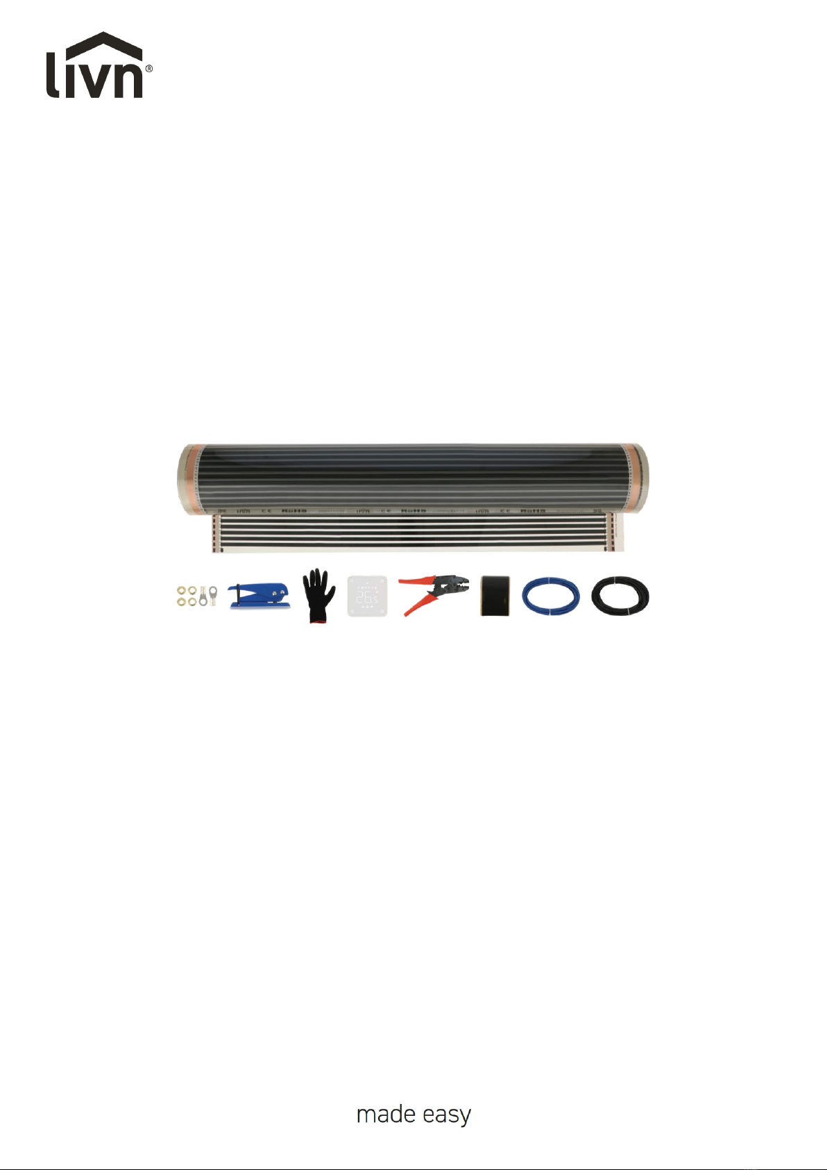
EN INFRARED FLOOR HEATING
NL INFRAROOD VLOERVERWARMING
FR CHAUFFAGE AU SOL INFRAROUGE
DE INFRAROT-FUSSBODENHEIZUNG
EN Instruction manual NL Handleiding FR Manuel d'instructions DE Bedienungsanleitung
EN INSTRUCTION MANUAL
Please read the instructions and user manual carefully before installing or using the floor heating,
and keep them retained for future reference. This manual is part of the floor heating and should be
stored with it. If sold to a third party, these user instructions should be supplied with the product.
Liability will not be accepted, and the warrant will not apply, in cases of improper use or failure to
follow the safety instructions. Should you encounter any problems, please contact a qualified
technician for help. For assistance or additional information, contact a qualified technician, the help
desk, or the retail outlet.
HEATING FILM INSTALLATION GUIDANCE
CAUTION!
•Suitable for the following types of finishing floors: wooden floors, laminate, parquet and click
PVC (not suitable for adhesive PVC!).
•Warning: the wooden floors, laminate, parquet and click PVC must have a minimum thickness of
5 mm and a maximum thickness of 22 mm. Contact your supplier for deviating thicknesses
advice.
•Before installation of heating film, clean the floor.
•Before installation, waterproof the floor first in case of moisture at the site.
•Do not use insulator coated with conductive material like silver foil (you should use heat-resisting
insulator).
•Take care not to damage heating filmor step on it whileinstallation. In case of damage on heating
film, insulate heating film using thin insulation tape.
•Check the contract power when installing heating films. And then you are allowed to install
heating films. If you don’t abide by this, a fire could break out.
•Calculate power consumption per 1 m printed on heating film and make sure that 75~80%
electric capacity of a thermostat is not exceeded.
•Make sure that you insulate the cut section with insulation tape.
•Do not put heavy things like a piano, refrigerator which could cause overheating on heating film.
•Livn heating foil may only be installed in dry places.
•Thick rugs or other insulating materials should never be placed on a floor with electrical heating.
•The thermostat needs to have the floor sensor properly installed to work.
•If you have a wooden floor, make sure you set the floor sensor to 28 °C. This function ensures
that the floor never reaches a temperature higher than 28 °C.
•Please visually check the foil for creasing or folding that may have happened during transit. Any
such damaged areas must be discarded.
•The heating foil should always be installed together with an RCD (Residual Current Device).
Formula for Power Consumption
: Power Consumption (Watt) = V(Voltage)²/R(Resistance)

•The rating of the heating foil must comply with the rating of the thermostat, the circuit breaker
and if needed the contactor. Good wiring practice must be observed. Installation must comply
with current building and wiring regulations. Connection cables must not come in contact with
the heating foil. The heating foil must be installed together with an RCD with a maximum
breaking current of 30 mA.
•Tip: after installation measure the resistances of all heating films installed by a resistance meter.
SECTION 1: INSTALLATION TOOLS AND MATERIAL
We highly appreciate you purchasing Livn infrared floor heating. We hope this installation guidance
helps the safe installation and solves any problems during this process.
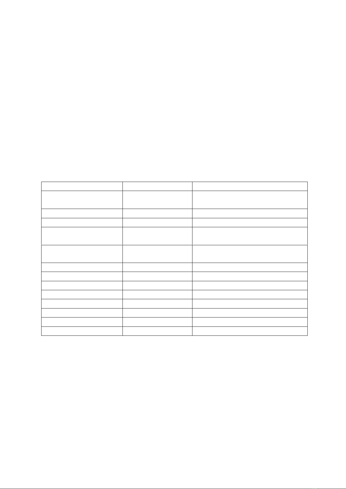
1.1 Tools
Name
Standard
Usage
Electric tester*
4.2 V to 500 V AC
50 ohm to 42 M-ohm
Voltage measurement
Resistance measurement
Electric leakage tester*
Electric leakage measurement
Infrared thermometer*
-30 ~ 300 °C
Heating film temperature measurement
Terminal / wire presser
0.75 ~ 5.5 mm
Eyelet terminal combination / Electric
wire connection
Eyelet punch
To make hole on heating film for eyelet
terminal
Stripper*
0.75 ~ 5.5 mm
Electric wire connection
Scissors*
Middle size
Heating film cutting
Cutting knife*
Middle size
Insulation pad cutting
Calculator*
Electricity consumption calculation
Driver*
Middle size (+/-)
Inlet plug, thermostat combination
Electric motion drill*
220 V using product
Thermostat fixating
Measure tapeline*
7.5 m length
To measure installation space
Gloves
*Not included
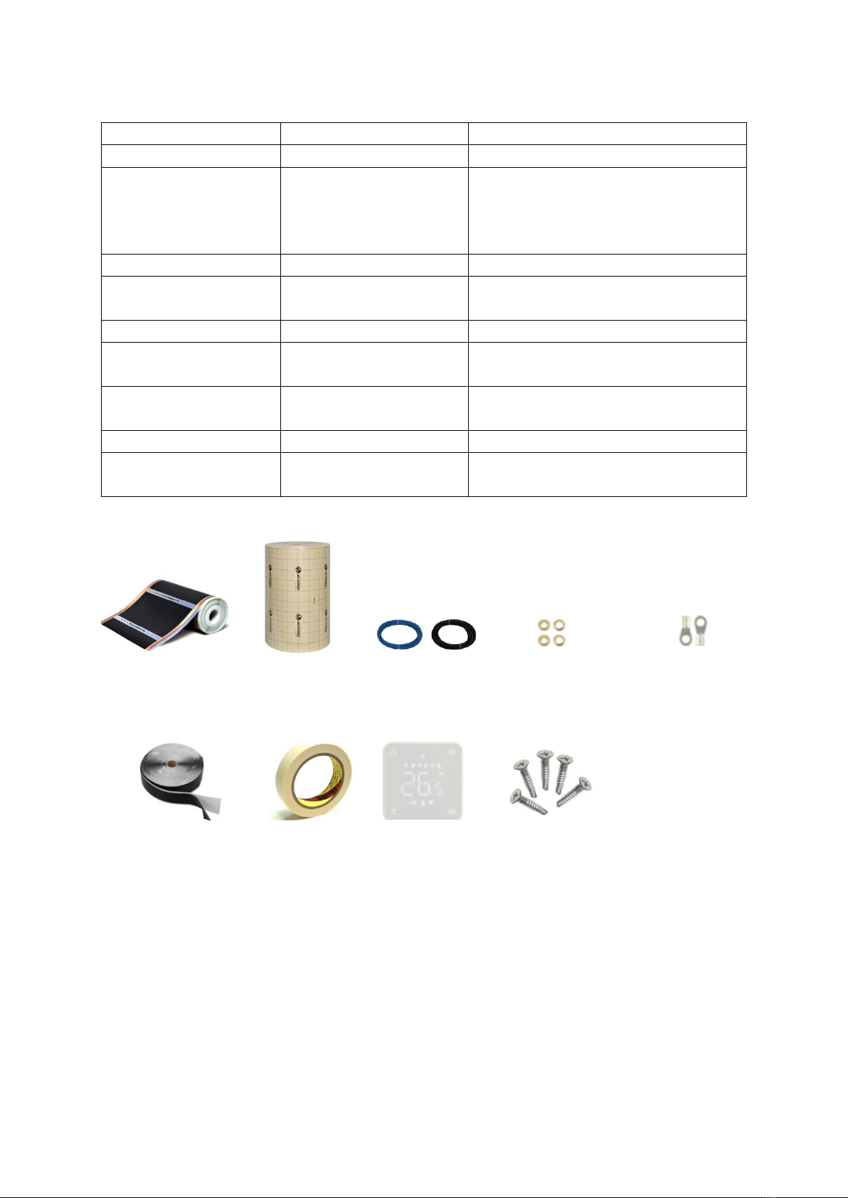
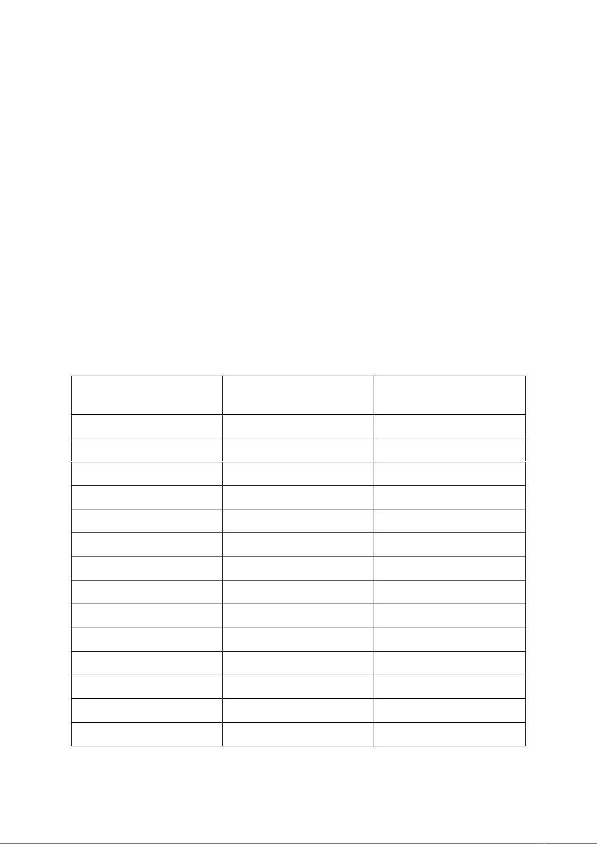
1.2 Materials
Name
Standard
Usage
Heating film
100 cm width
Heating material
Insulating underfloor*
Advised: minimum 3 mm
thickness. Minimum
insulation value 0.14
(m²K)/W
Prevention of floor coldness and
humidity
Electric wire
1.5 mm ~ 2.5 mm
Copper wire
Eyelet terminal
Combination of pressed terminal and
heating film
Pressed terminal
Tinned copper terminal
Electricity supply to heating film
Insulation tape
Insulation treatment regarding electric
wire connection spot
Paper / Duct tape*
Insulation pad, heating film and
electric wire fixation
Thermostat
3 Kw ~ 6 Kw capacity
Temperature control of heating film
Screw nail
Middle size
To fixate wire mould and thermostat
on the wall
*Not included
①Heating film
②Insulating
underfloor*
③Electric wire
④Eyelet terminal
⑤Pressed terminal
⑥Insulation tape
⑦Paper /
Duct Tape*
⑧Thermostat
⑨Screw Nail
SECTION 2: INSTALLATION PROCESS
Installation Planning Before installing the heating foil, make a sketch or drawing of the installation.
Plan where the thermostat should be placed. The thermostat should not be placed in direct sunlight.
It must be convenient for the user and near to the electrical supply, at a height of 1.5 m approx. Plan
where the wiring and the connection to the electrical supply should be placed. Plan the layout for
each heating foil panel. The heating foil must be placed side by side with no gaps. The heating foil
must cover as much floor area as possible
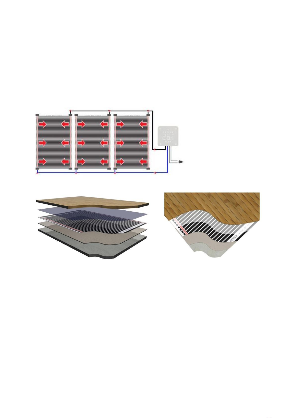
2.1 Figure of installation
①Base Floor
(Cement)
②Insulating
underfloor
③Heating
FILM
④Vapour barrier
foil
⑤Finishing Materials
(Wooden floors, laminate,
parquet and click PVC)
2.2 Heating film installation process
Step 1: Measure the voltage
Step 2: Floor cleaning
Step 3: Insulating underfloor cutting
Step 4: Insulating underfloor setting
Step 5: Heating film cutting
Step 6: Heating film fixating
Step 7: Electric wire connection
Step 8: Insulation tape treatment
Step 9: Power consumption calculation
Step 10: Thermostat connection
Step 11: Test operation
Step 12: Covering of heating film protecting material
Step 13: Finishing material installation
⑤
④
③
②
①
Diameter of the wire: Ø2.5 mm²
The IN terminal of the thermostat -
power, OUT terminal –Film
For each film circuit be connected in
parallel.
When cutting the film, the cutting line
on the copper foil, wrap with insulation
tape.
2.3 Preparation before heating-film installation
1. Check materials and tools once again before installation.
2. Check the total electrical power of the building to prevent any problem using heating-film and
other devices at the same time. When the electric capacity is not enough, you must increase the
capacity.
3. Check whether the electric voltage of the installation location matches the 230 V of the heating-
film.
4. Measure the size of the room where the heating-film will be installed and check the electricity
consumption of the heating-film box label. Finally, calculate the approximate total electricity
consumption.
5. Check the base cement floor whether it uses Styrofoam as an insulator. Never use Styrofoam
(Polystyrene) on the floor. It could cause a fire.
6. If the heating film is installed on a concrete or cement subfloor that is not yet completely dry, or
in a humid environment, we recommend installing a vapour-resistant foil on the base floor.
7. Arrange the direction of heating film installation considering maximum linear length for heating-
film installation.
8. All conditions of the site must be double checked before deciding installation.
Maximum permission current following electric wire thickness
Electric Wire Thickness (mm2)
Maximum Permission
Electric Current (Ampere)
Electricity Consumption (Watt)
1.5 mm2
19 Ampere
4.1 kW
2.5 mm2 (Included wiring)
26 Ampere
5.72 kW
4 mm2
35 Ampere
7.70 kW
6 mm2
45 Ampere
9.90 kW
10 mm2
61 Ampere
13.42 kW
16 mm2
81 Ampere
17.82 kW
25 mm2
106 Ampere
23.32 kW
35 mm2
131 Ampere
28.82 kW
50 mm2
158 Ampere
34.76 kW
70 mm2
200 Ampere
44.00 kW
95 mm2
241 Ampere
53.02 kW
120 mm2
278 Ampere
61.16 kW
150 mm2
318 Ampere
69.96 kW
185 mm2
362 Ampere
79.64 kW

2.4 Preparing the thermostat slot and laying the subfloor and heating film
1. Make sure the floor is clean and free from dust.
2. If the heating film is installed on a concrete or cement subfloor that is not yet completely dry, or
in a humid environment, we recommend installing a vapour-resistant foil on the base floor.
3. Cut a track in the wall from the thermostat with a curve into the floor. The slot should be cut to
the middle of a strip of heating foil, about 50 cm from the wall. Place a flexible pipe in the cut track.
4. Place the floor sensor in the flexible tube. The end of the sensor is visible at the end of the flexible
tube, but does not stick out! Place the sensor in the middle of a strip of heat foil.
5. Check the surface of the floor. For good contact and to prevent damage, it must be nice and flat.
Maximum deviation +/- 1 mm per metre.
6. If there are any irregularities in the floor, level them (for example with levelling compound).
7. Fill the slot with the flexible pipe and filling material (tile adhesive, levelling compound, etc.).
8. Make sure the floor surface is clean, dry, free of dust and grease.
9. Place the insulating subfloor. It must cover the entire floor area!
10. Tape the corners with the separately purchased tape to prevent the insulation from sliding. Leave
about 30 mm space for the power wires. Make sure that the floor is clean and that no sharp objects
can come into contact with or fall on the heating foil during installation. Plan the work in such a
way that it is not necessary to step over or onto the foil.
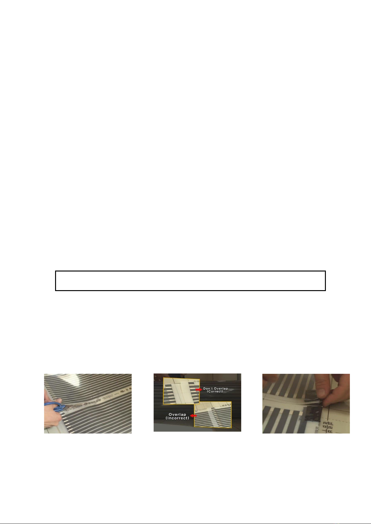
11. Unroll the heating foil.
12. Cut the heating film, you should cut the heating film along the dotted line.
13. Take notice that the length of your heating film in an unbroken line should be not over the
installable maximum length.
*Do not have heating film overlapped during installation. Make sure that the interval between
heating film be 1 cm –3 cm.
14. Cover the exposed copper ends, where no connecting wires will be connected, with a piece of
black insulating tape (check the laying schedule on the next page).
15. Roll the next piece of foil parallel to the first. Tape the heating-film elements to the insulation
subfloor to prevent them from shifting during further installation.
12
13
14
Installable maximum length of heating film in an unbroken line
100 cm wide heating film: 5 –6 m (Length)

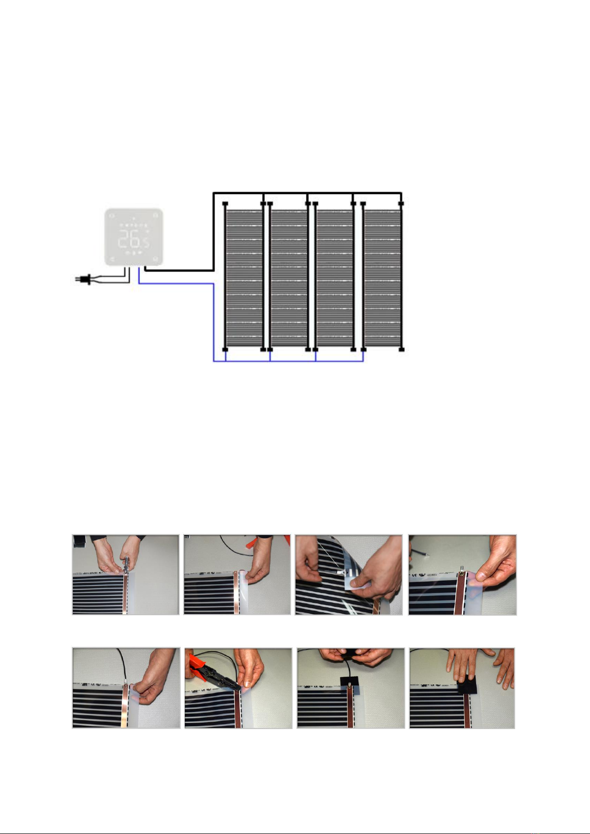
2.5 Connecting the wiring
After the entire floor area has been covered with heating foil, the wiring can be connected. On the side
where no connecting wires are connected, you must cover all copper conductors with insulating tape.
Pay attention! Take a good look at the laying schedule below. This diagram shows how the wiring must
be connected in parallel between the strips of heating film. Take a good look at how the blue and black
wiring is laid.
1. Pierce a hole in the copper foil with an eyelet punch.
2. Push the pressed terminal into the slot between the copper foil and silver booth bar.
3. Place an eyelet terminal on the pressed terminal.
4. Strip the wire with a stripper and put the wire in the eye of the pressed terminal.
5. Use the wire presser to flatten the eyelet terminal and pressed terminal so that the power wire is
fixed to the heating film. Test that the wiring is making good contact and is firmly attached to the
connector.
6. Use the insulating tape and stick it over the flattened pressed terminals and eyelet terminals with
wiring. PAY ATTENTION! The tape must extend at least 5 mm over the end of the connection and
cover all live parts.
1
2
3
4
5
6
2.6 Testing the installation
1. All heating foils must be connected during testing!
2. Measure the total resistance value of the heating foils and record this value on the check/control
card in this manual. Hang this check control card in the meter cupboard).
3. Calculate the actual power (wattage) with the following formula: power (230 V X 230 V) = 52,900
divided by the measured resistance value. Record this value on the check/control card.
4. Measure the total length of the heating foil and calculate the total
installed capacity with the formula: total installed power = total length x installed power of 150 W/m.
Record this value on the check/control card.
5. Make a sketch on the centre page and, preferably, take a photo of the installation.
2.7 Covering the heating foil
1. Cover the heating foil with vapour-resistant PE foil with a minimum thickness of 0.1 mm.
2. Place the floorboards (wooden floors, laminate, parquet or click PVC) according to the
manufacturer's instructions. Do not wear heavy or dirty footwear to prevent damage to the foil.
2.8 Connecting and installing the thermostat
For use and programming of the thermostat, please refer to the instructions enclosed with the
thermostat. Connection must be carried out by a recognised installer in accordance with the relevant
regulations. Always switch off the electricity in the meter cupboard before installing or removing the
thermostat. The MRC thermostat can be mounted in a single flush-mounted box 35 mm deep
(minimum depth), according to standard DIN formats. Check if the power is off.
Connecting the thermostat
DO • Mount the thermostat at eye level.
• Read the instructions fully so you get the best from our product.
DON’T • Do not install near to a direct heat source as this will affect functionality.
• Do not push hard on the LCD screen as this may cause irreparable damage.
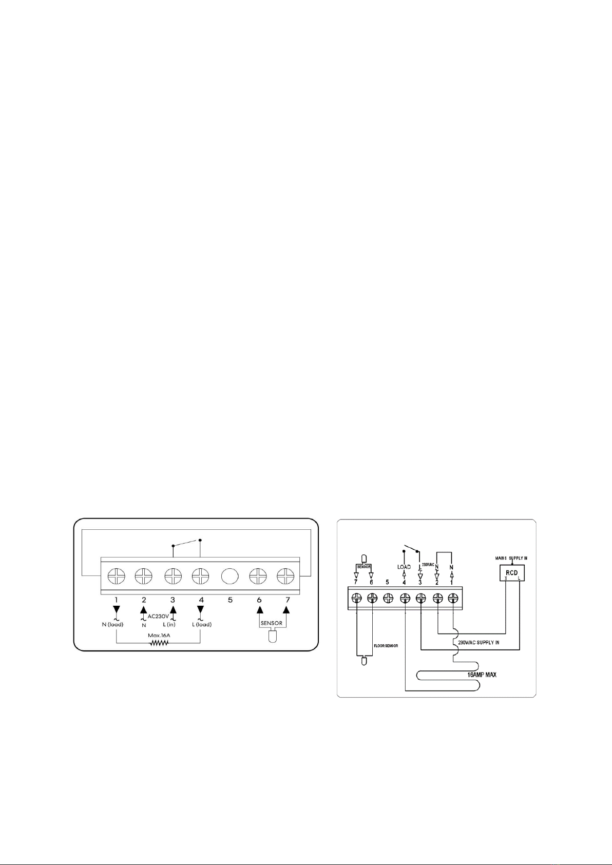
HEATING FILM (N) Heating cable connection wire
(terminal 1)
N Power Supply (Neutral) (terminal 2)
L Power Supply (Live) (terminal 3)
HEATING (L) Heating cable connecting wire (terminal 4)
FLOOR SENSOR Floor sensor connection (terminal 6 / 7)
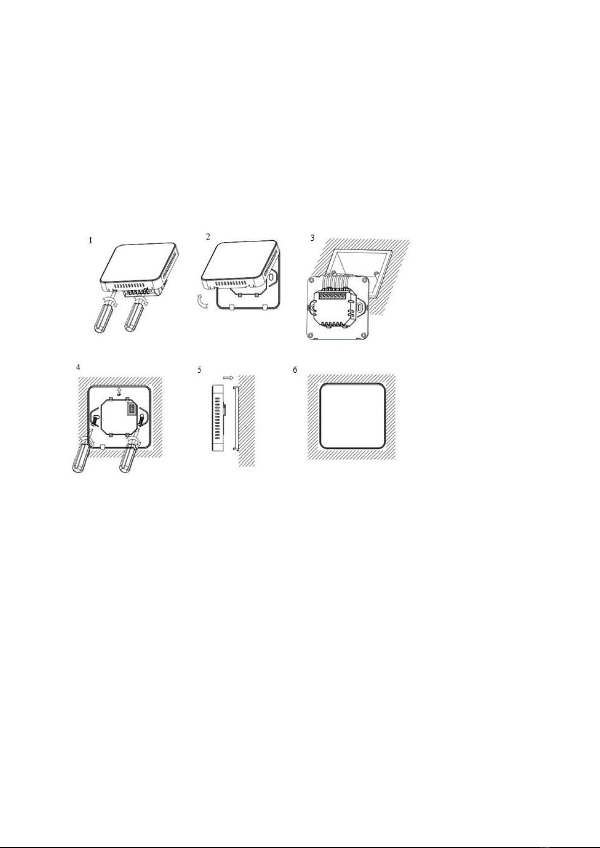
Installing the thermostat
The thermostat is designed to be flush mounted and requires a back box of 35 mm (minimum depth)
to be sunk into the wall prior to installation.
Step 1: Using a small screwdriver, slightly loosen the screw from the bottom face of the thermostat.
Then carefully separate the front half from the back plate.
Step 2 : Place the thermostat front somewhere safe.
Step 3: Terminate the thermostat as shown in the diagram.
Step 4: Screw the thermostat back plate securely into the back box.
Step 5: Clip the front of the thermostat onto the back plate.
SECTION 3: DISPOSAL
3.1 Disposal of the Product
The symbol on the product indicates that this product must not be treated as unsorted
municipal waste, but must be collected separately! Dispose of the product via a collection
point for the recycling of waste electrical and electronic equipment if you live within the
EU and in other European countries that operate separate collection systems for waste
electrical and electronic equipment. By disposing of the product in the proper manner, you
help to avoid possible hazards for the environment and public health that could otherwise
be caused by improper treatment of waste equipment. The recycling of materials contributes to the
conservation of natural resources. Therefore do not dispose of your old electrical and electronic
equipment with the unsorted municipal waste.
3.2 Disposal of Packaging Waste
Dispose of the packaging through your local recycling facilities. By disposing of the
packaging and packaging waste in the proper manner, you help to avoid possible hazards for
the environment and public health.
Product reference
5963000 Livn infrared floor heating Basic set 5 m2
5963010 Livn infrared floor heating Basic set 10 m2
5963020 Livn infrared floor heating Basic set 20 m2
5963100 Livn infrared floor heating supplement 5 m2
5963110 Livn infrared floor heating supplement 10 m2
8712757481873
8712757481880
8712757481897
8712757481903
8712757481910
Made in: China

CHECK & CONTROL CARD
ATTENTION! UNDERNEATH THE FLOORING IS A 230 VOLT HEATING FOIL
SYSTEM! DO NOT DRILL OR SCREW INTO THE FLOOR! PLEASE SEE THE
DRAWING FOR THE POSITION OF THE HEATING FOIL.
Control measurements:
Type of heating foil which is installed: Livn heating foil 150 W/m2
Total length of heating foil installed: ________ metre
Measured resistant value of the total installation ________ Ohm
Control Check calculation:
(150 W/m2 x metre-length = total Watts system)
150 W/m2 x _____ metre-length = ________ Watt
Difference ~ max. 5 %
(52900 : Ohm = total Watts system)
52900 : _______ Ohm = ________ Watt
Date:
Installed by:
Keep this control & check card in the meter cupboard in a visible place!

DRAWING OR PICTURES OF THE HEATING FOIL INSTALLATION

NL HANDLEIDING
Gelieve de instructies en handleiding aandachtig door te lezen alvorens het installeren en in gebruik
nemen van de vloerverwarming, en deze te behouden voor toekomstige raadpleging. Deze
handleiding is onderdeel van de vloerverwarming en dient erbij te worden bewaard. Bij verkoop aan
een derde dient deze gebruiksaanwijzing meegeleverd te worden met het product. Er wordt geen
aansprakelijkheid geaccepteerd en de garantie is niet van toepassing in het geval van onjuist gebruik
of het niet opvolgen van de veiligheidsinstructies. Indien u problemen ervaart, neem dan a.u.b.
contact op met een erkende monteur. Voor assistentie of meer informatie neemt u contact op met
een erkende monteur, de helpdesk of de winkel.
VERWARMINGSFOLIE INSTALLATIEGIDS
VOORZICHTIG!
•Geschikt voor de volgende soorten afwerkvloeren: houten vloeren, laminaat, parket en klik
PVC (niet geschikt voor zelfklevend PVC!).
•Waarschuwing: de houten vloeren, laminaat, parket en klik PVC moet een minimale dikte hebben
van 5 mm en een maximale dikte van 22 mm. Neem contact op met uw leverancier voor advies
omtrent afwijkende diktes.
•Maak de vloer schoon vóór installatie van de verwarmingsfolie.
•Maak vóór de installatie de vloer eerst waterdicht, in geval van mogelijk vocht op de vloer.
•Gebruik geen isolatie met geleidend materiaal, zoals zilverfolie (u dient warmtewerende isolatie
te gebruiken).
•Zorg dat u de verwarmingsfolie niet beschadigd of erop gaat staan tijdens de installatie. In geval
van schade aan de verwarmingsfolie, isoleert u de verwarmingsfolie met behulp van dunne
isolatietape.
•Controleer de contactkracht bij het installeren van verwarmingsfolies. Daarna mag u
verwarmingsfolies installeren. Indien u zich hier niet aan houdt, kan er brand uitbreken.
•Bereken de energieconsumptie per 1 m geprint op verwarmingsfolie en zorg dat het 75-80%
elektrisch vermogen van een thermostaat niet wordt overschreden.
•Zorg dat u het gesneden deel met behulp van isolatietape isoleert.
•Plaats geen zware dingen, zoals een piano of koelkast, die oververhitting kunnen veroorzaken op
de verwarmingsfolie.
•Livn verwarmingsfolie mag alleen worden geïnstalleerd op droge plekken.
•Dikke tapijten en andere isolatiematerialen dienen nooit op een vloer met elektrische
verwarming te worden geplaatst.
•Voor de juiste werking van de thermostaat dient de vloersensor correct geïnstalleerd te zijn.
•Indien u een houten vloer hebt, zorg dan dat u de vloersensor op 28 °C instelt. Deze functie
zorgt dat de vloer nooit warmer wordt dan 28 °C.
•Controleer de folie a.u.b. visueel op kreukels of vouwen die kunnen zijn ontstaan tijdens
transport. Dergelijke beschadigde delen dienen te worden verwijderd.
Formule voor Energieverbruik
: Energieconsumptie (Watt) = V(Spanning)²/R(Weerstand)
•De verwarmingsfolie moet altijd samen met een RCD (aardlekschakelaar) worden geïnstalleerd.
•De beoordeling van de verwarmingsfolie moet overeenkomen met de beoordeling van de
thermostaat, de stroomonderbreker en, indien nodig, de schakelaar. Correcte bekabeling dient
in acht te worden genomen. Installatie moet overeenkomen met de huidige bouw- en
bekabelingsregelgeving. Verbindingskabels mogen niet in contact komen met de
verwarmingsfolie. De verwarmingsfolie moet tegelijk met een RCD met een maximale
verbrekingsstroom van 30 mA worden geïnstalleerd.
•Tip: meet na installatie de weerstand van alle geïnstalleerde verwarmingsfolies m.b.v. een
aardweerstandsmeter.
ONDERDEEL 1: INSTALLATIE VAN TOOLS EN MATERIALEN
Wij zijn u zeer erkentelijk voor het aanschaffen van Livn infrarood vloerverwarming. We hopen dat
deze installatiegids helpt bij een veilige installatie en dat de gids een oplossing kan bieden voor
eventuele problemen tijdens het proces.
1.1 Tools
Naam
Standaard
Gebruik
Elektrische tester*
4.2 V tot 500 V AC
50 ohm tot 42 M-ohm
Voltagemeting
Weerstandsmeting
Elektrische lektester*
Elektrische lekstroommeting
Infrarood thermometer*
-30 ~ 300 °C
Verwarmingsfolie temperatuur meting
Aansluiting / draadtang
0,75 ~ 5,5 mm
Oog-aansluiting combinatie /
Elektrische draadverbinding
Pons oog
Om een gat te maken in de
verwarmingsfolie voor oog--aansluiting
Striptang*
0,75 ~ 5,5 mm
Elektrische draadverbinding
Schaar*
Middelgroot
Snijden van verwarmingsfolie
Mes*
Middelgroot
Snijden van isolatie
Rekenmachine*
Electricity consumptie calculatie
Driver*
Middelgroot (+/-)
Ingangsplug, thermostaat combinatie
Elektrische boor*
product op 220 V
Bevestiging thermostaat
Rolmaat*
7,5 m lengte
Om installatieruimte te meten
Handschoenen
*Niet inbegrepen

1.2 Materialen
Naam
Standaard
Gebruik
Verwarmingsfolie
100 cm breedte
Verwarmingsmateriaal
Isolerende ondervloer*
Advies: minimaal 3 mm
dikte. Minimale
isolatiewaarde 0,14
(m²K)/W
Voorkomen van koude en vochtige
vloer
Elektrische draad
1,5 mm ~ 2,5 mm
Koperdraad
Oog aansluiting
Combinatie of ingedrukte aansluiting
en verwarmingsfolie
Ingedrukte aansluiting
Vertinde koperen
aansluiting
Elektriciteitsaanvoer naar
verwarmingsfolie
Isolatietape
Isolatiebehandeling m.b.t. elektrische
draadverbinding spot
Papieren tape /
Ducttape*
Vastzetten isolatiepad,
verwarmingsfolie en elektrische draad
Thermostaat
3 kW ~ 6 kW capaciteit
Temperatuurcontrole van de
verwarmingsfolie
Schroefnagel
Middelgroot
Om draadmal en thermostaat te
bevestigen aan de muur
*Niet inbegrepen
① Verwarmingsfolie
② Isolerende
ondervloer*
③ Elektrische draad
④ Oogjes-
aansluiting
⑤ Ingedrukte
aansluiting
⑥ Isolatie-
tape
⑦ Papieren
tape /
Ducttape*
⑧
Thermostaat
⑨ Schroefnagel

ONDERDEEL 2: INSTALLATIEPROCES
Installatieplanning. Maak vóór het installeren van de verwarmingsfolie een schets of tekening van de
installatie. Plan waar de thermostaat moet worden geplaatst. De thermostaat moet niet in direct
zonlicht worden geplaatst. Hij moet praktisch zijn voor de gebruiker en zich bevinden nabij een
stroomvoorziening, op een hoogte van ongeveer 1,5 m. Plan waar de bedrading en de verbinding
naar de stroomtoevoer moeten worden geplaatst. Plan de indeling voor ieder
verwarmingsfoliepaneel. De verwarmingsfolie moet zij aan zij geplaatst worden, zonder
tussenopeningen. De verwarmingsfolie moet zoveel mogelijk vloeroppervlak bedekken.
2.1 Afbeelding van installatie
① Basisvloer
(cement)
② Isolerende
ondervloer
③
Verwarmingsfolie
④
Dampwerende
folie
⑤ Afrondingsmaterialen
(houten vloeren, laminaat,
parket en klik PVC)
2.2 Verwarmingsfolie installatieproces
Stap 1: Meet de spanning
Stap 2: Vloerreiniging
Stap 3: Snijden isolerende ondervloer
Stap 4: Plaatsen isolerende ondervloer
Stap 5: Snijden verwarmingsfolie
Stap 6: Verwarmingsfolie vastzetten
Stap 7: Elektrische draadverbinding
Stap 8: Isolatietape aanbrengen
Stap 9: Stroomconsumptie berekenen
Stap 10: Thermostaat verbinden
Stap 11: Testen van werken
Stap 12: Bedekken van verwarmingsfolie
beschermingsmateriaal
Stap 13: Afronden van materiaalinstallatie
⑤
④
③
②
①
Diameter van de draad: Ø2,5 mm²
De IN aansluiting van de thermostaat -
power, OUT aansluiting –Folie
Voor ieder parallel te verbinden
filmcircuit.
Zorg bij het snijden van de folie dat de
snijlijn op de koperen folie zit, wikkel deze
in met isolatietape.
2.3 Voorbereiding vóór installatie van de verwarmingsfolie
1. Controleer de materialen en tools nogmaals voorafgaand aan de installatie.
2. Controleer het totale elektrische vermogen van het gebouw ter voorkoming van problemen bij
gebruik van verwarmingsfolie en andere apparatuur op hetzelfde moment. Wanneer hetelektrisch
vermogen niet voldoet, dient u dit te verhogen.
3. Controleer of de elektrische spanning van de installatielocatie overeenkomt met de 230 V van de
verwarmingsfolie.
4. Meet de grootte van de ruimte waar de verwarmingsfolie zal worden geïnstalleerd en controleer
het stroomverbruik op het etiket van de verpakking van de verwarmingsfolie. Ten slotte berekent
u het geschatte totale elektrische verbruik.
5. Controleer de basis cement vloer op het gebruik van polystyreen als isolator. Gebruik nooit
polystyreen op de vloer. Dit kan brand veroorzaken.
6. Wanneer de verwarmingsfolie wordt geïnstalleerd op een ondervloer van beton of cement die nog
niet geheel droog is of zich in een vochtige omgeving bevindt, raden wij het aanbrengen van een
dampbestendige folie op de basisvloer aan.
7. Regel de richting van de verwarmingsfolie installatie, waarbij u de maximale lineaire lengte voor
installatie van verwarmingsfolie in het achterhoofd houdt.
8. Alle condities van de plek moeten tweemaal worden gecheckt voordat tot installatie wordt
besloten.
Maximaal toegelaten stroom naar dikte van elektrische draad
Elektrische draaddikte (mm2)
Maximaal toegelaten
elektrische stroom (Ampère)
Elektriciteitsverbruik (Watt)
1,5 mm2
19 Ampère
4,1 kW
2,5 mm2 (inbegrepen bedrading)
26 Ampère
5,72 kW
4 mm2
35 Ampère
7,70 kW
6 mm2
45 Ampère
9,90 kW
10 mm2
61 Ampère
13,42 kW
16 mm2
81 Ampère
17,82 kW
25 mm2
106 Ampère
23,32 kW
35 mm2
131 Ampère
28,82 kW
50 mm2
158 Ampère
34,76 kW
70 mm2
200 Ampère
44,00 kW
95 mm2
241 Ampère
53,02 kW
120 mm2
278 Ampère
61,16 kW
150 mm2
318 Ampère
69.96 kW
185 mm2
362 Ampère
79.64 kW
2.4 Voorbereiden van de thermostaatsleuf en het leggen van de ondervloer en verwarmingsfolie
1. Zorg dat de vloer schoon en stofvrij is.
2. Als de verwarmingsfolie wordt geïnstalleerd op een ondervloer van beton of cement die nog niet
geheel droog is, of zich in een vochtige omgeving bevindt, raden wij aan om een dampbestendige
folie op de basisvloer aan te brengen.
3. Snij/knip een baan in de muur vanaf de thermostaat, met een bocht in de vloer. De sleuf dient te
worden gesneden tot het midden van een strip van de verwarmingsfolie, ongeveer 50 cm van de
muur. Plaats een flexibele pijp in de uitgesneden baan.
4. Plaats de vloersensor in de flexibele buis. Het eind van de sensor is zichtbaar aan het einde van de
flexibele buis, maar steekt er niet uit! Plaats de sensor in het midden van een strip
verwarmingsfolie.
5. Controleer het oppervlak van de vloer. Voor goed contact en om schade te voorkomen moet deze
mooi en vlak zijn. Maximale afwijking is +/- 1 mm per meter.
6. Indien er zich onregelmatigheden in de vloer bevinden, vlak deze dan af (bijvoorbeeld m.b.v.
egalisatiemiddel).
7. Vul de sleuf met de flexibele pijp erin met vulmateriaal (tegellijm, egalisatiemiddel, enz.).
8. Zorg dat het vloeroppervlak schoon, droog en stof- en vetvrij is.
9. Plaats de isolatie-ondervloer. Deze dient het gehele vloeroppervlak te bedekken!
10. Tape de hoeken met de apart gekochte tape, om te voorkomen dat de isolatie gaat schuiven. Laat
ongeveer 30 mm ruimte voor de voedingskabels. Zorg dat de vloer schoon is en dat er geen scherpe
objecten in contact kunnen komen met, of vallen op, de verwarmingsfolie tijdens installatie. Plan
het werk zodanig in dat het niet nodig is om op of over de folie heen te stappen.
11. Rol de verwarmingsfolie uit.
12. Snij/knip de verwarmingsfolie, u dient de verwarmingsfolie langs de stippellijn af te
knippen/snijden.
13. Houd er rekening mee dat de lengte van uw verwarmingsfolie in een ononderbroken lijn de
installeerbare maximumlengte niet overschrijdt.
*Laat verwarmingsfolie niet overlappen tijdens installatie. Zorg dat de intervallen tussen de folie
1-3 cm bedragen.
14. Bedek de blootgelegde koperen einden waarop geen verbindingsdraden zullen worden
aangesloten met een stuk zwart isolatietape (zie het legschema op de volgende pagina).
15. Rol het volgende deel van de folie parallel aan het eerste. Plak de verwarmingsfolie-elementen aan
de isolatie-ondervloer om te voorkomen dat deze gaan schuiven tijdens verdere installatie.
12
13
14
Installeerbare maximumlengte van verwarmingsfolie in een ononderbroken lijn
100 cm brede verwarmingsfolie: 5 –6 m (Lengte)
2.5 Aansluiten van de bedrading
Nadat het gehele vloeroppervlak is bedekt met verwarmingsfolie kan de bedrading worden
aangesloten. Aan de kantwaar geen verbindingsdraden zijn aangesloten, dient u alle koperen geleiders
te bedekken met isolatietape.
Pas op! Kijk goed naar het onderstaande legschema. Dit schema toont hoe de bedrading in parallel
moet worden verbonden tussen de verwarmingsfolie strips. Kijk goed hoe de blauwe en zwarte
bedrading is gelegd.
1. Prik een gat in de koperfolie met een pons.
2. Druk de ingedrukte aansluiting in de sleuf tussen de koperfolie en zilveren strip.
3. Plaats een oogjes-aansluiting op de ingedrukte aansluiting.
4. Strip de draad met een striptang en plaats de draad in het oogje van de ingedrukte aansluiting.
5. Gebruik de kabeltang om de oogjes-aansluiting en ingedrukte aansluiting plat te maken, zodat de
stroomkabel vastzit aan de verwarmingsfolie. Test dat de bedrading goed contact maakt en goed
is vastgezet aan de verbinder.
6. Gebruik de isolatietape en plak deze over de plat gemaakte ingedrukte aansluitingen en oog-
aansluitingen met bedrading. LET OP! De tape moet minstens 5 mm uitsteken over het einde van
de verbinding en alle onder spanning staande delen bedekken.
1
2
3
4
5
6
This manual suits for next models
4
Table of contents
Languages:
Other livn Heater manuals


Popular Heater manuals by other brands


Sunpak
Sunpak S34?TSR Basic operation

Strend Pro
Strend Pro VT-020 instruction manual

Bio Green
Bio Green Frosty 2500 Installation and operating instructions

Prem-I-Air Elite
Prem-I-Air Elite EH1264 quick start guide

Kaisai
Kaisai GOLD AU-100H6 installation manual

Gabarron
Gabarron TGV200 operating instructions