LIW MayorSIT User manual

MANUAL FOR
MayorSIT - ORTHOPAEDIC SEAT FOR
CHILDREN, STABILISING THE BACK AND
HEAD
Edition 2 - 31.08.2018

Page 2 MayorSIT - ORTHOPAEDIC SEAT FOR CHILDREN, STABILISING THE BACK AND HEAD Edition 2
NOTE! THE MANUFACTURER IS SOLELY RESPONSIBLE FOR THE EQUIPMENT
PURCHASED FROM A DIRECT REPRESENTATIVE OF LIW CARE TECHNOLOGY, OR IN
SPECIALIZED MEDICAL SHOP REPRESENTING LIW CARE TECHNOLOGY IN POLAND.
NOTE! DEVICE IS DEDICATED FOR INDOOR USE.
NOTE! THERE IS A DANGER OF ENTRAPMENT OR/ AND COMPRESSION OF THE USERS’S
OR THE CARER’S BODY PARTS INSIDE THE GAPS/ SLOTS BETWEEN ELEMENTS DURING
USE, SERVICE, INSTALLATION AND ADJUSTING ALL MECHANISMS. THESE ACTIONS
SHOULD BE TAKEN WITH EXTRA PRECAUTION. AFTER MAKING ADJUSTMENTS, IT IS
NECESSARY TO STABILIZE THE DEVICE POSITION BY RETIGHTENING THE KNOBS/ BOLTS
CORRECTLY.
NOTE! THE PRODUCT PACKAGING SHOULD BE RETAINED IN CASE THE PRODUCT NEEDS
TO BE TRANSPORTED BACK FOR WARRANTY PURPOSES.
NOTE! DO NOT LEAVE A CHILD IN MAYORSIT UNSUPERVISED.
NOTE! DO NOT EXCEED MAXIMUM USER WEIGHT FOR MAYORSIT ORTHOPAEDIC SEAT
FOR CHILDREN.
NOTE! DO NOT USE MAYORSIT ORTHOPAEDIC SEAT FOR CHILDREN IF THERE ARE
FAULTY, BROKEN OR MISSING PARTS.
NOTE! IT IS NECESSARY TO READ THE MANUAL BEFORE START-UP.

MayorSIT - ORTHOPAEDIC SEAT FOR CHILDREN, STABILISING THE BACK AND HEAD Edition 2 Page 3
1Introduction ....................................................................................................................................................................... 4
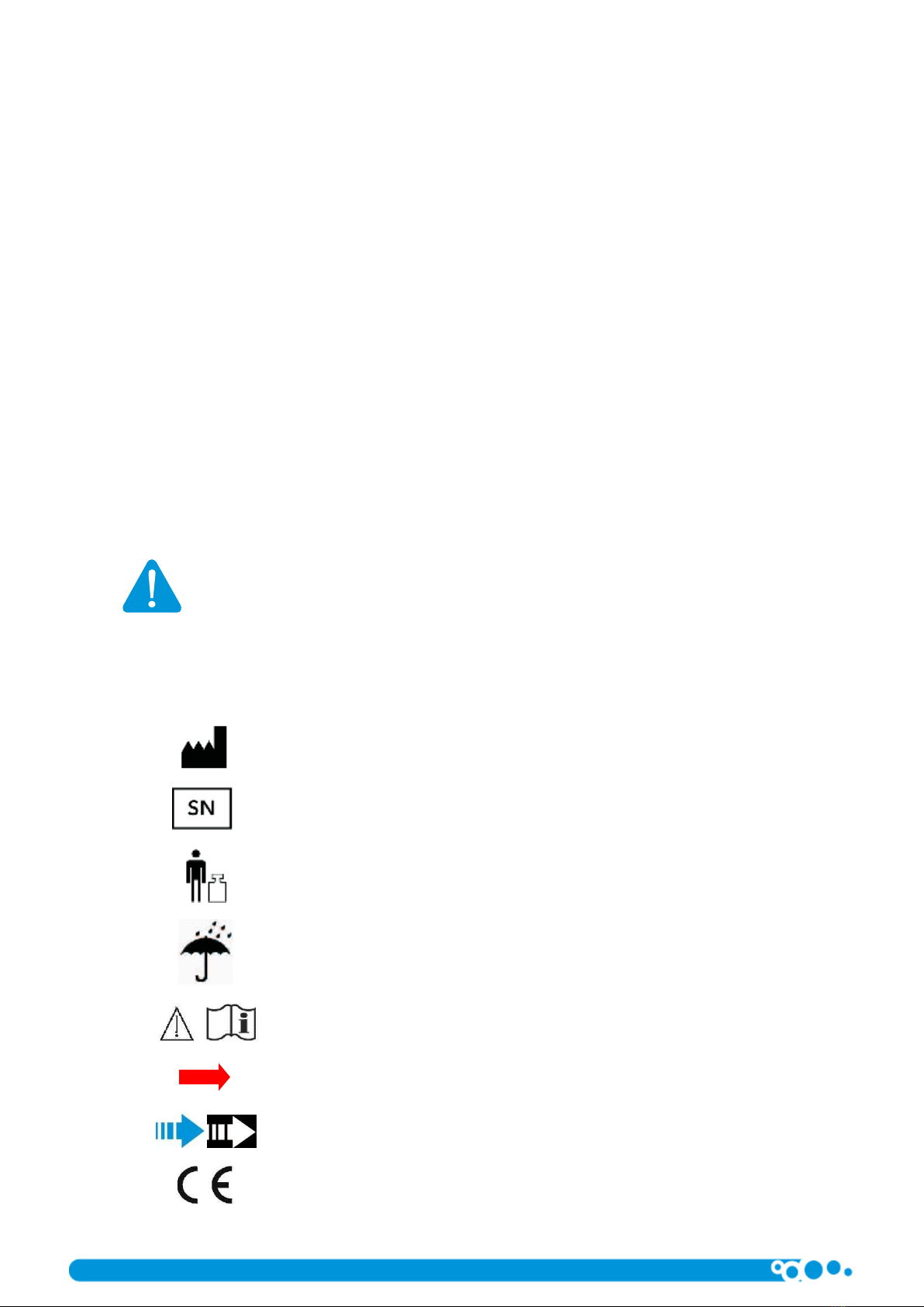
2Symbol meaning ................................................................................................................................................................ 4
3Compliance with the safety requirements for medical devices......................................................................................... 5
4Indications for product use................................................................................................................................................ 5
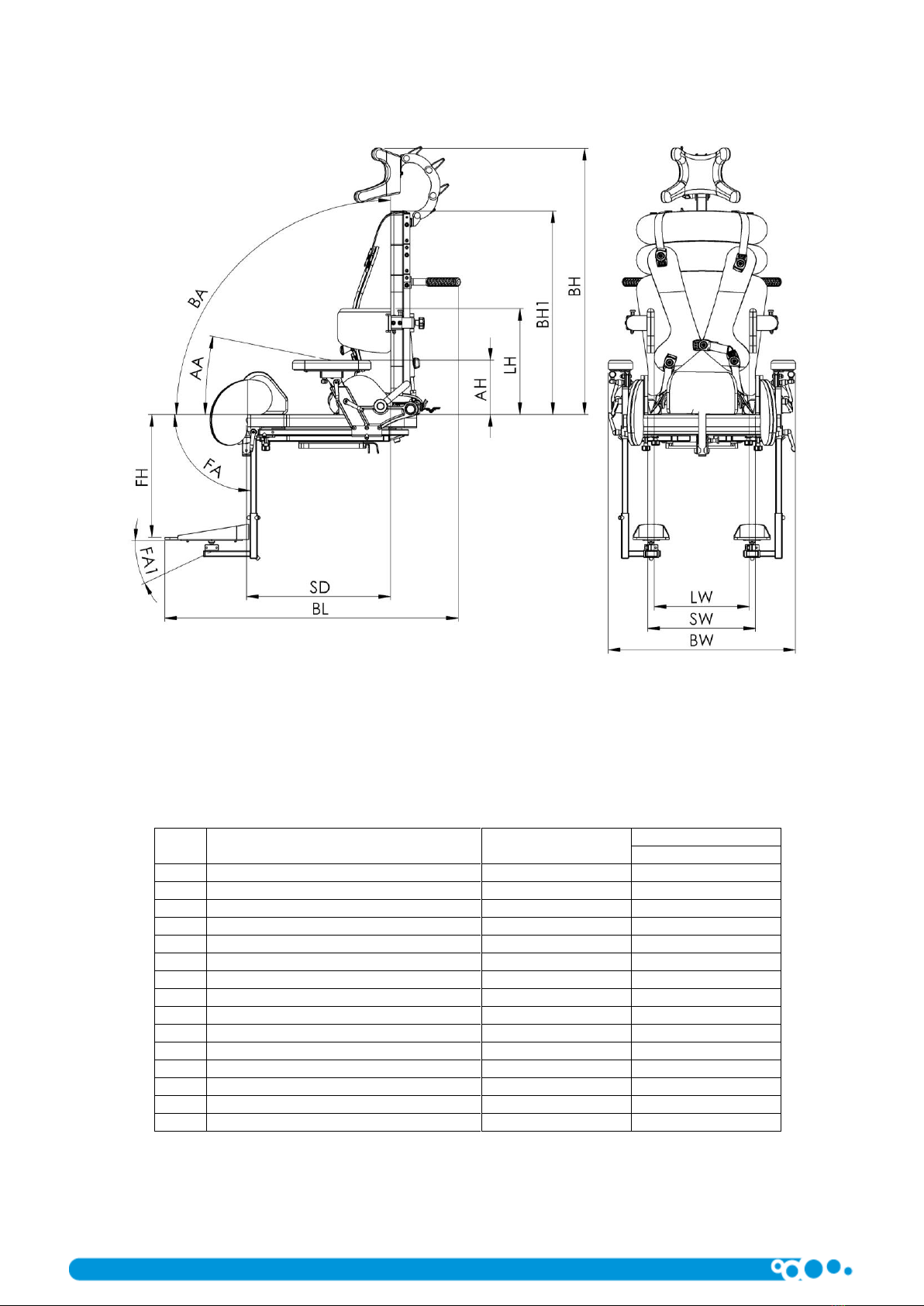
5Weight and dimensions ..................................................................................................................................................... 6
6Structure of MayorSIT - orthopaedic seat for children, stabilising the back and head...................................................... 7
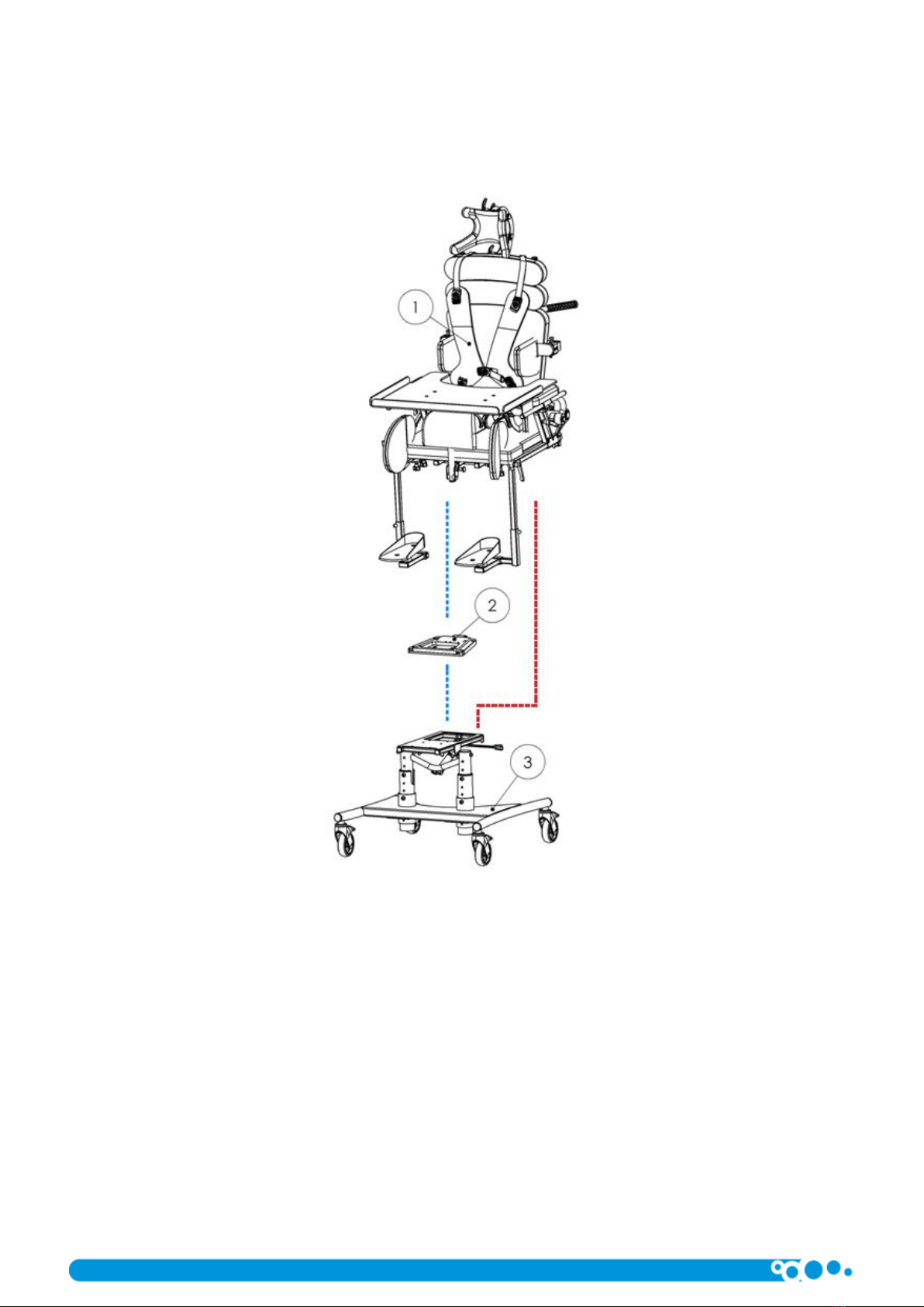
7MayorSIT - orthopaedic seat for children, stabilising the back and head with base frame ............................................... 8
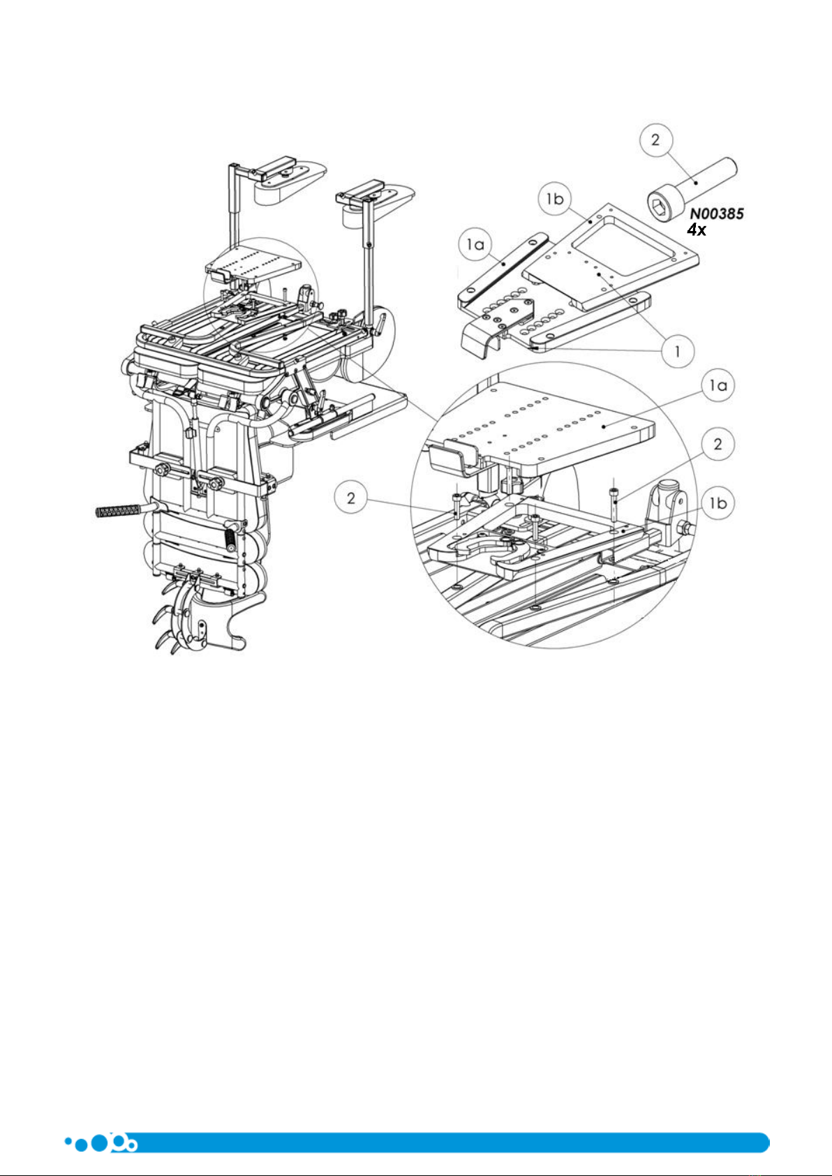
8Mounting the orthopaedic seat using the interchangeable system –aluminium trapezoid ............................................. 9
9Mounting the orthopaedic seat directly on the base frame ............................................................................................ 10
10 Chassis frames for MayorSIT, orthopaedic seat for children, stabilising the back and head ........................................... 11
10.1 Mayor Chassis Frame ........................................................................................................................................ 11
10.1.1 Weight and dimensions ............................................................................................................................... 11
10.1.2 General structure of Mayor Chassis Frame ................................................................................................. 12
10.1.3 Adjusting the Mayor Chassis Frame............................................................................................................. 12
10.1.4 Accessories .................................................................................................................................................. 17
11 Detailed description of mounting and adjusting MayorSIT - orthopaedic seat for children, stabilising the back and head20
11.1 Description of mounting the backrest extensions............................................................................................. 20
11.2 Description of mounting horned headrest. ....................................................................................................... 21
11.3 Adjusting the horned headrest.......................................................................................................................... 22
11.4 Description of adjusting the tilt angle of the backrest ...................................................................................... 23
11.5 Description of adjusting the laterals (side supports)......................................................................................... 24
11.6 Description of a quick side supports tilt ............................................................................................................ 25
11.7 Description of adjusting the seat width............................................................................................................. 26
11.8 Description of fitting the vest............................................................................................................................ 27
11.9 Description of adjusting the vest....................................................................................................................... 27
11.10 Description of fitting pelvic support belt........................................................................................................... 28
11.11 Description of adjusting the pelvic support belts .............................................................................................. 28
11.12 Description of adjusting the seat depth ............................................................................................................ 29
11.13 Description of ischial tuberosity support adjustment ....................................................................................... 30
11.14 Description of adjusting the seat depth for a patient with asymmetrical leg length ........................................ 31
11.15 Description of adjusting height of the armrest ................................................................................................. 32
11.16 Description of adjusting the angle of the armrest............................................................................................. 32
11.17 Description of mounting the pommel ............................................................................................................... 33
11.18 Description of a quick swing back pommel ....................................................................................................... 34
11.19 Description of adjusting the pommel ................................................................................................................ 35
11.20 Description of fitting the foot supports............................................................................................................. 36
11.21 Description of adjusting the height of the foot supports .................................................................................. 37
11.22 Description of adjusting angle of the foot supports.......................................................................................... 37
11.23 Description of adjusting the distance of the foot supports............................................................................... 38
11.24 Description of adjusting the angle and position of the platforms ..................................................................... 39
11.25 Description of mounting knee supports ............................................................................................................ 40
11.26 Description of knee support .............................................................................................................................. 41
11.27 Description of assembling the rehabilitation tray ............................................................................................. 42
11.28 Description of adjusting the lumbar support .................................................................................................... 43
12 Moving MayorSIT, orthopaedic seat for children, stabilising the back and head, Mayor Frame..................................... 44
13 Cleaning and maintenance .............................................................................................................................................. 45
13.1 Desinfection ...................................................................................................................................................... 46
14 Service and Maintenance................................................................................................................................................. 46
15 Identification plate........................................................................................................................................................... 46
WARRANTY CARD .................................................................................................................................................................. 47

Page 4 MayorSIT - ORTHOPAEDIC SEAT FOR CHILDREN, STABILISING THE BACK AND HEAD Edition 2
1Introduction
Thank you for purchasing MayorSIT - orthopaedic seat for children, stabilising the back and head, by LIW Care Technology
Care Sp. z o.o. We are certain that the innovative device with advanced anatomical body adjustment features will improve the
comfort of work and leisure time for the user in a sitting position.
Developed by LIW Care Technology Sp. z o.o., the MayorSIT - orthopaedic seat for children stabilising the back and head
has been designed to provide an alternative to standard orthopaedic seats with limited anatomical adjustment ranges and
bespoke seats which perfectly map out the body curvatures, however, they do not give the opportunity to correct the user’s body
posture.
We ensured that the seat is as simple to use as possible while giving the opportunity to fit the anatomical shape of the
user, as well as correct the posture.
1.1 Warnings & Safety Information
For LIW Care Technology Sp. z o. o., the most important thing is to protect the patients who use our equipment. For
ensuring the safety of MayorSIT users, the following recommendations should be adopted:
1. Please read the Instructions before the first use. In case any questions or doubts should arise, please contact your
dealer or the manufacturer.
2. Please make sure that all the information, tips and warnings contained in these chapters are fully understood.
In these instructions for LIW Care Technology Sp. z o. o. products, you will find information marked with „NOTE!” symbol.
It is used to the draw reader’s particular attention to the text. It looks as follows:
UWAGA! THE SYMBOL IS USED TO DRAW THE READER’S ATTENTION TO THE TEXT
WHICH IS MARKED WITH THIS SYMBOL. FAILURE TO COMPLY WITH THE INSTRUCTIONS
MAY ENDANGER THE HEALTH AND SAFETY OF THE USER OR IT MAY DAMAGE THE
PRODUCT.
2Symbol meaning
Manufacturer’s name and date of manufacture
Serial Number
User’s permissible weight
Avoid contact with water
Note! Follow product instructions
Unlocking direction
Movement direction
Mark of conformity in accordance with EU Directive
93/42 EEC Annex. VII, concerning medical devices

MayorSIT - ORTHOPAEDIC SEAT FOR CHILDREN, STABILISING THE BACK AND HEAD Edition 2 Page 5
3Compliance with the safety requirements for medical devices
MayorSIT - orthopaedic seat for children, stabilising the back and head meets the essential requirements of the MDD 93/42
EEC for medical devices.
MayorSIT - orthopaedic seat for children, stabilising the back and head in accordance with Annex IX of the MDD 93/42 EEC is
non-invasive non-active I class medical device according to rule 1.
The Declaration of Conformity for this product can be found in manufacturer's Sales Department.
NOTE! IF PRODUCT HAS BEEN MODIFIED USING NON - AUTHENTIC PARTS OR PARTS
PRODUCED BY ANOTHER MANUFACTURER, REMOVE THE CE MARK.
4Indications for product use
MayorSIT - orthopaedic seat for children, stabilising the back and head is designed for children suffering paralysis and
triplegia or tetra- plegia; with diplegia, hemiplegia or hemiparesis.
It is recommended for children who have been diagnosed with:
• cerebral palsy (paralysis cerebralis infantium),
• muscular dystrophies,
• paralysis,
• spina bifida,
• myelomeningocele,
• spinal injury,
• traumatic brain injury,
• strokes,
• other medical conditions with paresis, paralysis, locomotor disabilities enabling their self-sufficient movement.

Page 6 MayorSIT - ORTHOPAEDIC SEAT FOR CHILDREN, STABILISING THE BACK AND HEAD Edition 2
5Weight and dimensions
Fig. 1
No.
Dimension
Dimension symbol
Dimension [cm]
XL
1
Seat depth
SD
25÷50
2
Backrest height without headrest
BH1
48; 58; 68
3
Backrest height with headrest
BH
69; 79; 89
4
Laterals height
AH
18÷23
5
Chest supports length
LH
19÷46
6
Footrests height
FH
16÷50
7
Seat width
SW
12÷45
8
Laterals width (side supports)
LW
32÷50
9
Base width
BW
53
10
Footrest assembly angle
FA1
-/+5°
11
Footrest angle adjustment
FA
0°÷90°
12
Armrest angle adjustment
AA
-10°÷10°
13
Backrest angle adjustment
BA
-5°÷25°
14
Maximum user’s weight
100kg
15
Basic seat weight
26,5kg

MayorSIT - ORTHOPAEDIC SEAT FOR CHILDREN, STABILISING THE BACK AND HEAD Edition 2 Page 7
6Structure of MayorSIT - orthopaedic seat for children, stabilising the back and head
Fig. 2
1) Horned head rest*
2) Vest*
3) Side support
4) Armrest
5) Pelvic belts*
6) Seat
7) Backrest with lumbar support system
8) Pushing handle
9) Rehabilitation tray*
10) Leg abduction wedge*
11) Knee blocks*
12) Foot platform with 3d adjustment system*
*Accessory marked with an asterisk is optional.

Page 8 MayorSIT - ORTHOPAEDIC SEAT FOR CHILDREN, STABILISING THE BACK AND HEAD Edition 2
7MayorSIT - orthopaedic seat for children, stabilising the back and head with base frame
MayorSIT - orthopaedic seat for children, stabilising the back and head can be mounted on the base frame by using an
interchangeable system or directly on the frame without the interchangeable system.
Fig. 3
1) MayorSIT - orthopaedic seat for children, stabilising the back and head
2) Interchangeable system –aluminium trapezoid*
3) Mayor Frame*
* Accessory marked with an asterisk is optional.

MayorSIT - ORTHOPAEDIC SEAT FOR CHILDREN, STABILISING THE BACK AND HEAD Edition 2 Page 9
8Mounting the orthopaedic seat using the interchangeable system –aluminium trapezoid
Fig. 4
To mounting the interchangeable system for the orthopaedic chair, screw part 1b in with 2 bolts (3) using a 5mm Allen key.
The two remaining bolts (2) retighten using nuts (5), insert nuts between the interface system and the frame (4). Sockets for the
bolts are located underneath the seat unit.

Page 10 MayorSIT - ORTHOPAEDIC SEAT FOR CHILDREN, STABILISING THE BACK AND HEAD Edition 2
9Mounting the orthopaedic seat directly on the base frame
Fig. 5
Mount the seat using 4 screws (1).

MayorSIT - ORTHOPAEDIC SEAT FOR CHILDREN, STABILISING THE BACK AND HEAD Edition 2 Page 11
10 Chassis frames for MayorSIT, orthopaedic seat for children, stabilising the back and head
NOTE! DEVICE IS INTENDED FOR A SINGLE USER ONLY.
NOTE! DO NOT EXCEED MAXIMUM LOAD; ATTACHING ANY OBJECTS OR LEANING ON
THE DEVICE MY CAUSE IT TO OVERTURN.
NOTE! EXTREME SETTINGS AND UNFAVOURABLE POSITION (LEANING OUT) INCREASE
THE RISK OF OVERTURNING.
NOTE! THE FOOTREST OF THE DEVICE IS USED FOR SUPPORTING THE FEET AND UNDER
NO CIRCUMSTANCES SHOULD IT BE USED TO STAND ON. THERE IS A RISK OF TIPPING.
THE SAME REFERS TO THE ARMREST; IT MUST NOT BE USED TO SUPPORT THE WHOLE
BODY.
NOTE! IT IS FORBIDDEN TO CARRY THE FRAME WITH USER IN IT.
NOTE! DEVICE IS INTENDED FOR FLAT AND SOLID SURFACES. MOVING THE DEVICE
OVER OBSTACLES SUCH AS STAIRS, THRESHOLDS OR CURBS IS ONLY POSSIBLE WITHOUT
THE USER.
10.1 Mayor Chassis Frame
10.1.1 Weight and dimensions
Fig. 6
No.
Dimension
Dimension
symbol
Dimension
[cm]
1
Frame lenght
BL
77
2
Frame width
BW
67
3
Seat height
BH
33-56
4
Seat platform seat
BA
-10°÷30°
5
Frame maximum load
130 kg
6
Frame weight
18,7 kg

Page 12 MayorSIT - ORTHOPAEDIC SEAT FOR CHILDREN, STABILISING THE BACK AND HEAD Edition 2
10.1.2 General structure of Mayor Chassis Frame
Fig. 7
1. Base frame
2. Bar
3. Seat platform bar
4. Seat platform
5. Gas spring for adjusting the tilt angle of the seat platform
6. Wheels
Mayor Frame consists of a chassis (1) equipped with wheels (6) with a wheel locking mechanism. Adjusting the seat
platform is achieved by using the positioning slots in the bars (2) and correspondingly in the platform bars (3) as well as the
chassis frame (1). Adjusting the tilt angle of the seat platform (4) is by a gas spring (5).
10.1.3 Adjusting the Mayor Chassis Frame
NOTE! AFTER EVERY SINGLE ADJUSTMENT, YOU NEED TO MAKE SURE THAT ALL THE
COMPONENTS ARE CORRECTLY POSITIONED AND LOCKED.
10.1.3.1 Locking the wheels of the Chassis Frame
Chassis Frame Mayor is supplied with four swivel wheels. The wheels are equipped with brakes which allow complete
locking of the wheels. To lock a wheel, press the brake lever (1) until a distinctive ‘click’ sound is heard. To unlock the wheel, pull
the brake lever (1) up.
Fig. 8

MayorSIT - ORTHOPAEDIC SEAT FOR CHILDREN, STABILISING THE BACK AND HEAD Edition 2 Page 13
10.1.3.2 Adjusting the height of the seat platform
NOTE! ADJUSTING THE HEIGHT OF THE SEAT PLATFORM MUST BE PERFORMED WITH
LOCKED WHEELS AND WHERE POSSIBLE WITHOUT THE SEAT MOUNTED ON. UNDER NO
CIRCUMSTANCES MUST THE HEIGHT ADJUSTMENT BE PERFORMED WHILE THE PATIENT
IS IN THE SEAT. ONLY A DEVICE SECURED IN SUCH MANNER CAN BE SUBJECTED TO
ADJUSTMENTS.
NOTE! DURING ADJUSTING THE HEIGHT OF THE SEAT PLATFORM, SPECIAL ATTENTION
MUST BE PAID AS THERE IS A DANGER OF HAND ENTRAPMENT BY THE MOBILE
ELEMENTS.
NOTE! AFTER ADJUSTING THE HEIGHT OF THE PLATFORM, CHECK IF ALL SCREWS AND
NUTS ARE WELL TIGHTENED.
Fig. 9
Adjusting the height of the seat height is done in two stages. The first range allows adjustments in the range of 12cm, every 3cm.
Firstly, remove the screws (1) together with the washers (2) and (3) from the bar (4) Fig.10 and Fig.11. Next, set the required
height of the bar (4) Fig. 12 so that the screws can be inserted again in to the slots in the base (5).

Page 14 MayorSIT - ORTHOPAEDIC SEAT FOR CHILDREN, STABILISING THE BACK AND HEAD Edition 2
Fig. 10
Fig. 11

MayorSIT - ORTHOPAEDIC SEAT FOR CHILDREN, STABILISING THE BACK AND HEAD Edition 2 Page 15
Fig. 12
The second range allows adjustments in the range of 14cm, every 3,5cm Fig.13 and Fig.14. To achieve this, undo the screws
(1) together with the washers (2) and the nut (3) from the bar (4) Fig.13. Next, set the height of the seat platform by properly
setting the combination of slots in the platform bar (5) and the slot in the bar (4) Fig.14.
Fig. 13

Page 16 MayorSIT - ORTHOPAEDIC SEAT FOR CHILDREN, STABILISING THE BACK AND HEAD Edition 2
Fig. 14
Options available for obtaining the height of the seat platform in regard to the basis depending on the use of the mounting
slots:
[cm]
E
F
G
H
J
A
33
36,5
40
43,5
47
B
36
39,5
43
46,5
50
C
39
42,5
46
49,5
53
D
42
45,5
49
52,5
56
10.1.3.3 Adjusting the tilt angle of the seat platform
NOTE! ADJUSTING THE TILT ANGLE OF THE SEAT PLATFORM MUST BE PERFORMED
WITH THE BRAKES APPLIED ON. ONLY A DEVICE SECURED IN THIS WAY CAN BE
SUBJECTED TO SAFE ADJUSTMENTS.
NOTE! DURING ADJUSTING THE TILT ANGLE OF THE SEAT PLATFORM, SPECIAL
ATTENTION MUST BE PAID AS THERE IS A RISK OF HAND ENTRAPMENT BY THE MOBILE
PARTS.
NOTE! DURING ADJUSTING THE TILT ANGLE OF THE PLATFORM WITH USER IN IT, HOLD
THE RETARDANT’S LEVER WITH ONE HAND AND THE HANDLE WITH THE OTHER ONE.
UNDER NO CIRCUMSTANCES HOLD/ PUT HANDS NEAR THE PLATFORM MECHANISM;
THERE IS A RISK OF HAND ENTRAPMENT!

MayorSIT - ORTHOPAEDIC SEAT FOR CHILDREN, STABILISING THE BACK AND HEAD Edition 2 Page 17
Fig. 15
Adjusting the tilt angle of the seat platform (1) is possible in the ranges -10° do +30° horizontally and is shown in Fig. 15. This
adjustment is done by pulling back the gas spring lever (2) located under the seat platform. If the seat is not mounted on the seat
platform (1), adjusting the angle is done by pressing on the back part of the platform. To adjust the tilt angle with the seat fitted
on, hold the seat with one hand and the gas spring lever (2) with the other one. Once the required angle has been achieved,
release the gas spring lever; this will lock the platform’s tilt angle.
10.1.4 Accessories
10.1.4.1 Seat interchangeable system –the aluminium trapezoid
NOTE! AFTER MOUNTING THE ELEMENTS OF THE SEAT INTERCHANGEABLE SYSTEM ON
THE SEAT PLATFORM FRAME, CHECK IF ALL BOLTS AND NUTS ARE TIGHTENED.
ELEMENTS WHICH ARE NOT TIGHTENED MAY CAUSE THE INTERCHANGEABLE SYSTEM
TO DETACH ITSELF AND THIS MAY RESULT IN INJURING THE PATIENT.
Mayor Chassis Frame can be equipped with a fast seat interchangeable system. To mount the system, fit the bottom part of
the system (1) on to the seat platform (3) using the joining elements (4). Top part (2) of the system is fitted directly on to the seat.

Page 18 MayorSIT - ORTHOPAEDIC SEAT FOR CHILDREN, STABILISING THE BACK AND HEAD Edition 2
Fig. 16
Fitting the seat using the aluminium trapezoid show in Fig. 17:
place the seat with the fitted trapezoid (2) over the interchangeable system (1);
slide the seat into the interchangeable system (1) according to the blue arrow till it stops. You will hear a spontaneous
lock of the seat on the base;
check the system lock by pulling the seat in the direction opposite to the blue arrow.
Fig. 17
Removing the seat using the aluminium trapezoid is shown in Fig 18:
pull the release handle marked with the red arrow in the direction of the blue arrow,
hold the handle and push the seat while sliding it out of the base of the interchangeable system (1),
lift and remove the seat together with the trapezoid element (2) from the base of the interchangeable system.

MayorSIT - ORTHOPAEDIC SEAT FOR CHILDREN, STABILISING THE BACK AND HEAD Edition 2 Page 19
Fig. 18
10.1.4.2 Parted footrests
NOTE! AFTER FITTING THE FOOTRESTS, CHECK TO MAKE SURE THE FOOTREST RODS
HAVE NOT BEEN PULLED OUT THE SEAT PLATFORM FRAME AT THE MAXIMUM SETTING.
EXTREME FOOTREST SETTING MAY CAUSE THE FOOTREST TO LOSE ITS STABILITY AND
CAUSE DAMAGE.
NOTE! WHEN THE FOOTRESTS ARE NOT INSTALLED, THE MOUNTING SLOTS MUST BE
SECURED WITH THE PLASTIC CAPS.
The frame has the facility to have parted footrests fitted on. To install the footrest (1) and (2), remove the caps (3) from the
seat frame rods (5), undo the locking bolts (4) to allow sliding the rods in to the mounting slots easily. After setting the footrest in
the required position, retighten the locking bolts (4) so that footrests (1) and (2) stay in place. The maximum setting of the
footrests is marked with a sign on the footrest rod. Remember to replace the caps (3) in the rods after dismantling the footrests.
Fig. 19

Page 20 MayorSIT - ORTHOPAEDIC SEAT FOR CHILDREN, STABILISING THE BACK AND HEAD Edition 2
11 Detailed description of mounting and adjusting MayorSIT - orthopaedic seat for children,
stabilising the back and head
11.1 Description of mounting the backrest extensions.
Fig. 20
To extend the backrest, add the extensions. Backrest extensions, depending on their number can extend the backrest from
48 cm up to 68 cm, with 10 cm spaces in between them. Backrest extensions (1) insert into the backrest pipe slots, then tighten
the bolt (4). The end of the pipe cover with a cap (2).
Table of contents
Popular Mobility Aid manuals by other brands

Lifestyle
Lifestyle Venture XP manual

DHG
DHG SystemRoMedic EasySlide 1420 Instructions for use

MDH
MDH VITEA CARE VCBP0031 2FSS user manual

BHM Medical
BHM Medical JHI-9720010 Assembly instructions

Direct Healthcare Group
Direct Healthcare Group GATE Bure Double 2.0 Technical manual

MTS Systems
MTS Systems SAFETYSURE THE KNEE SLING quick guide