Llutico N125-DE User manual
Biological Microscope
Model Number: N125-DE
User Manual
Store Name:LluticoDE
Contact:+8618106639615
Email:[email protected]
This manual is for biological microscope Model N125-DE.
To ensure the safety, obtain optimum performance and to familiarize yourself fully with the use of this microscope,
it is recommended strongly that you study this manual thoroughly before operating the microscope.

Contents N125-DE
Contents ............................................................................................................
User Notices .....................................................................................................
1. Components Name...................................................................................
2. Assembly ....................................................................................................
2.1 Assembly Diagram .................................................................................
2.2 Assembly procedure ............................................................................
3. Adjustment and Operation......................................................................
3.1 Adjustment set diagram .......................................................................
3.2 Adjustment and Operation..................................................................
4. Technical Specifications..........................................................................
4.1 Main specifications .................................................................................
4.2 Eyepieces and Objectives ....................................................................
5. Outfit ..............................................................................................................
6. TroubleShooting Guide ..........................................................................
7. Warranty .......................................................................................................
1
2
3
4
4
5
9
9
11
13
13
13
14
15
17

Use Notices N125-DE
Ⅰ. Safety note
1. Open the box carefully to avoid the accessories, like lens, dropping to ground or being damaged.
2. Do keep the instrument out of direct sunlight, high temperature or humidity, dusty and easy shaking
environment. Make sure the stage is flat, horizontal and firm enough.
3. When moving the microscope, carefully carry it with the handle and the base.
4. Make sure the instrument is earthed, toavoid lighting strike.
5. For safety, be sure the main switch is in “O” (off) state and cut off the power supply before replacing
the bulb or the fuse. If you replace the bulb during use or right after use, allow the lamp bulb and
the lamp house to cool completely before touching.
(Designated bulb:1W S-LED or 6V20W Halogen Lamp)
6. Check the input voltage: be sure the input voltage which is signed in the back of the microscope is
consistent with the power supply voltage, or it will bring a serious damage to the instrument.
7. Always use the power cord provided by Novel.
8. The electrical equipment of the microscope should be discard as electronic waste.
Ⅱ. Maintenance and Care
1. All the lenses have been adjusted properly; do not dismount them by yourself please.
2. The nosepiece and coarse and fine focusing parts are so delicate that it is forbidden to disassemble
them carelessly by yourself.
3. Keep the instrument clean, and do not pollute the optical element when wiping away the dust on
the instrument.
4. The contaminations on the prism, like fingerprints and oil smudges, could be gently wiped with a
piece of soft cloth or tissue paper, gauze which has been immersed in pure alcohol or ether. (Note
that the alcohol and ether are highly flammable, do keep them away from the fire or potential
sources of electrical sparks, and use them in a drafty room as possible as you can.)
5. Do not attempt to use organic solvents to clean the microscope components other than the glass
components. To clean them, use a lint-free, softcloth slightly moistened with a diluted neutral
detergent.
6. When using, if the microscope is splashed by liquid, cut off the power at once, and wipe away the
splash.
7. Do not disassemble any parts of the microscope, as this will affect the function or reduce the
performance of the microscope.
8. Place the instrument in a cool, dry position. When not using the microscope, keep it covered with a
dust cover. Make sure the lamp socket is cool before covering the microscope.
2

1. Components Name N125-DE
Eyepiece Binocular viewing head
Nosepiece
Objective
Illumination
Main body
Condenser
Biological Microscope N125-DE
3
Stage

2.1 Assembly Diagram
2.Assembly N125-DE
4
The following figure shows the installation sequence of the components. The number in the figure
shows the assembly steps.
★ Before installing, be sure every components is clean, do not score any parts or glass surface.
★ Keep well with hexagon wrench provided. When changing the components, you will need it
again.
④
③
①
②
10X Eyepiece
20X Eyepiece
Objective
Main body Power cord
Binocular Viewing Head
WF20X WF20X
2.2 Assembly procedure
N125-DE
5
Fig.1
Fig.2
Fig.3
Fig.4
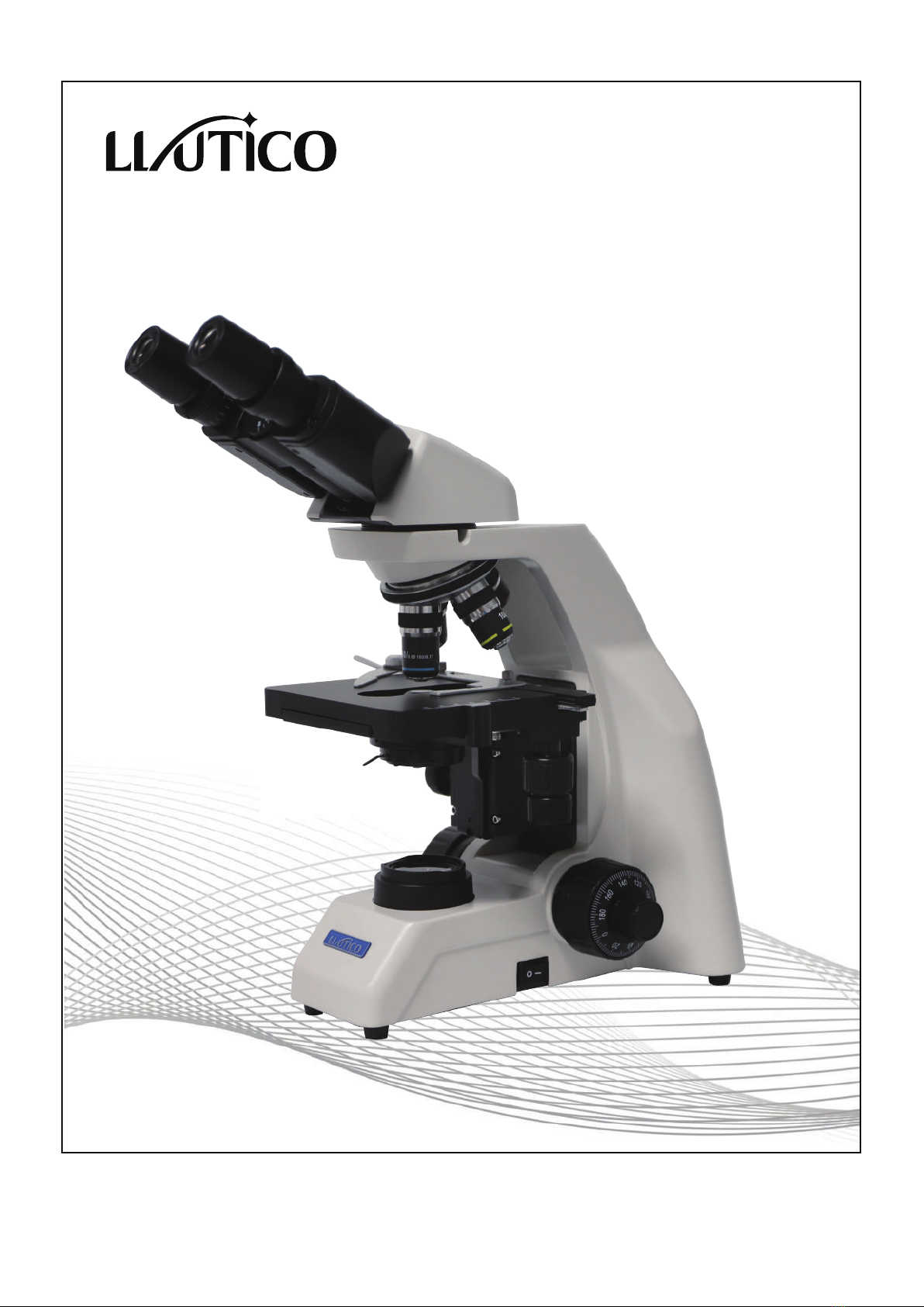
2.2.1 Installing binocular viewing head(Fig.1-2)
Insert the binocular viewing head into the microscope
head and turn it to a proper position, then tight it.
Insert the eyepiece into the eyepiece tube until they
are against each other, as shown in Fig.4.
2.2.2 Installing the eyepiece (Fig3-4)
N125-DE
6
Fig.5
Fig.6
Fig.7
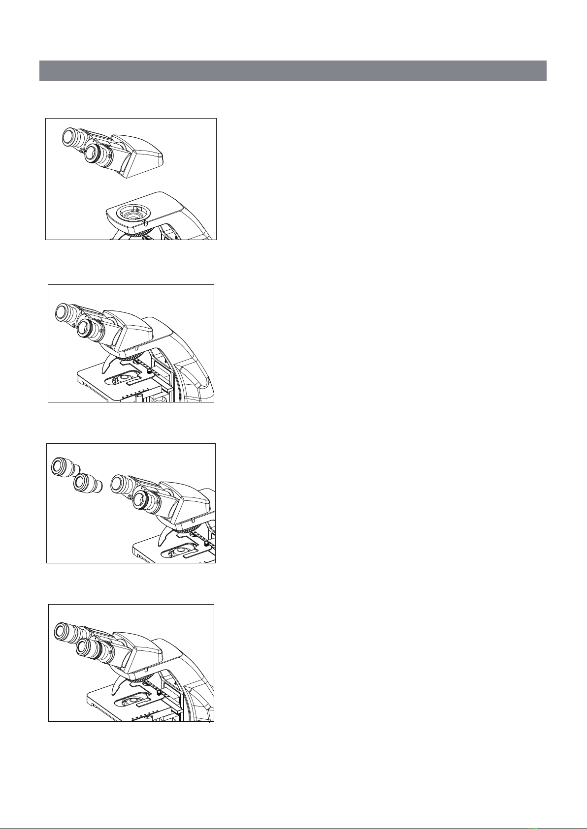
2.2.3 Installing the objective(Fig.5-6)
1. Adjusting the coarse focus knob until the support
device of the mechanical stage reaches its low limit
position.
2. Screw the lowest magnification objective into the
nosepiece from the left or the right side, then
revolve the nosepiece clockwise and mount other
objectives by the sequence of low to high
magnification
◇ Installing objective this way will make the change of
magnification to be easier during using.
★ Clean the objective regularly, for lens is
susceptible to dust.
★ When operating, use 10 × magnification
objective to search and focus specimen
firstly, then replace with higher
magnification objective if necessary.
★ When replacing the objective, slowly turn
the nosepiece until you hear “clicked”,
that means the objective is in place.
2.2.4 Mounting the filters(Fig.7)
1. Open the condenser carriage①;
2. Place the required filter②into the condenser ,
then close the condenser carriage。
★ the filter of the standard outfit is green and
baby blue.
①
②
N125-DE
7
Fig.8
Fig.9
Fig.10
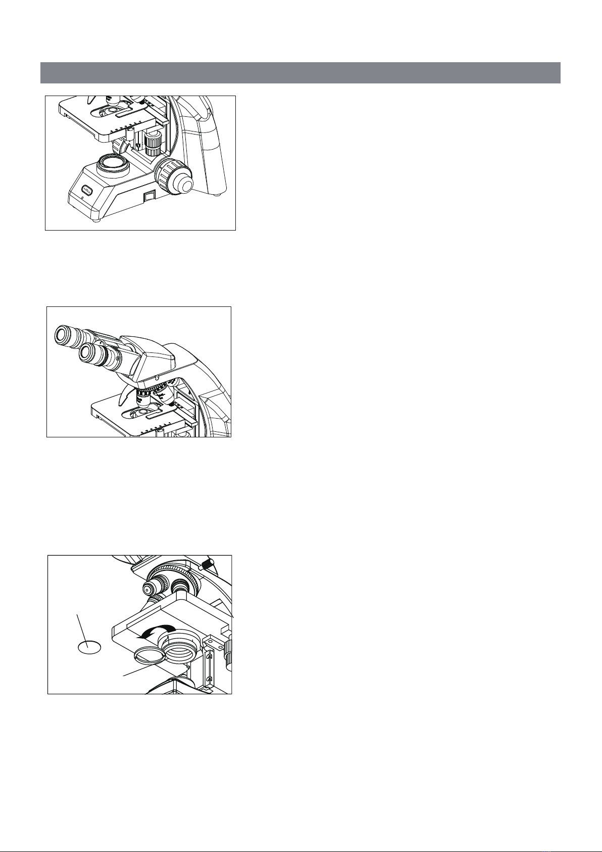
2.2.5 Connecting the Power Cord (Fig.8-10)
★ The cable and cords are vulnerable when
bent or twisted, never subject the power cord
to excessive force.
1. Set the main switch①o “O” (off) state before
connecting the power cord.
2. Insert the plugs②into the power jack③f the
microscope safely.
3. Plug the power cord④into the power supply
receptacle⑤. Make sure the connection is well.
★ Do use the supplied power cord all the time.
If lost or damaged, select the same standard
cord, please.
★ A wide range of voltage ,like 100V~240V,
is acceptable for this microscope.
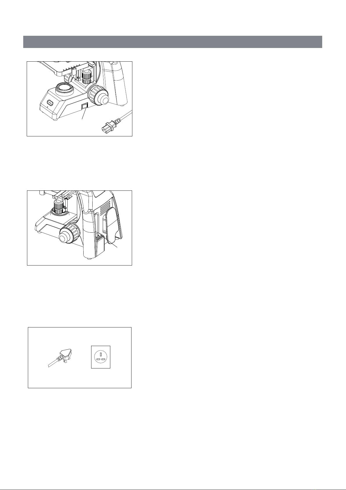
2.2.6 Replacing the fuse(Fig.9-10)
Do remember to set the main switch①to the state “O”
(OFF) and unplug the power cord before replacing the
fuse. Rotate the fuseout of the holder ③ , replace with
a new fuse, then rotate it back to the holder again.
④ ⑤
③
①
②
N125-DE
8
Fig.11
Fig.12
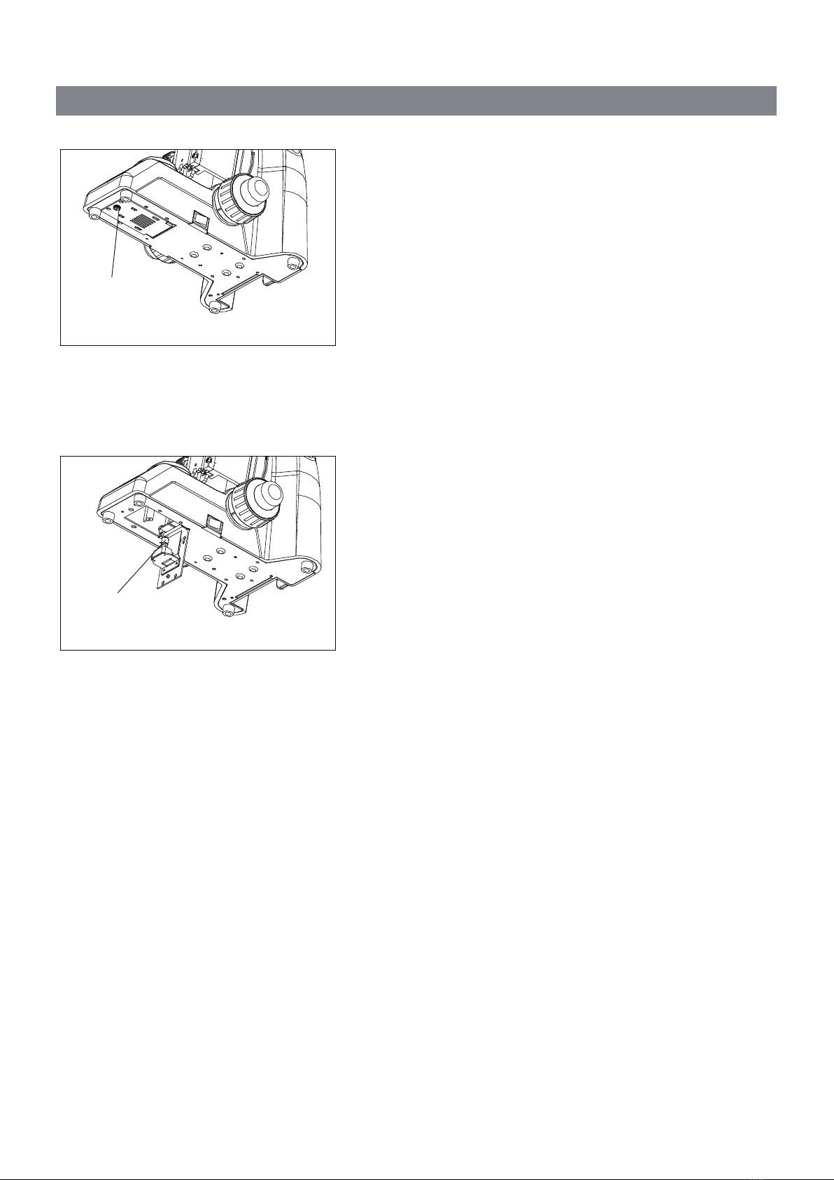
2.2.7 Installing and Replacing the bulb
(Fig.11-12)
◇ Please use the specified halogen Lamp 6V20W.
1. Loosing the screw①。
2. Hold the bulb②after you wrap it with gauze or
other protection materials, and then insert its
pindeeply intothe jack in the lamp holder.
3. Duringmicroscope using or soon after it is turned
off, the bulb, the lamp house and nearby parts will
be very hot and will cause serious burns. Please
turn the main switch to“O” (off) and disconnect the
power plug, and make sure the bulb, the lamp
room and periphery are all cool. Then, you can do
your replacing.
★ Insert the bulb gently. Squeezing too hard
will damage the bulb.
★ To prevent reduced bulb life or cracking, do
not touch the bulb with bare hands. If
fingerprints are accidentally left on the bulb,
wipe the bulb with a soft cloth.
②
①
N125-DE
9
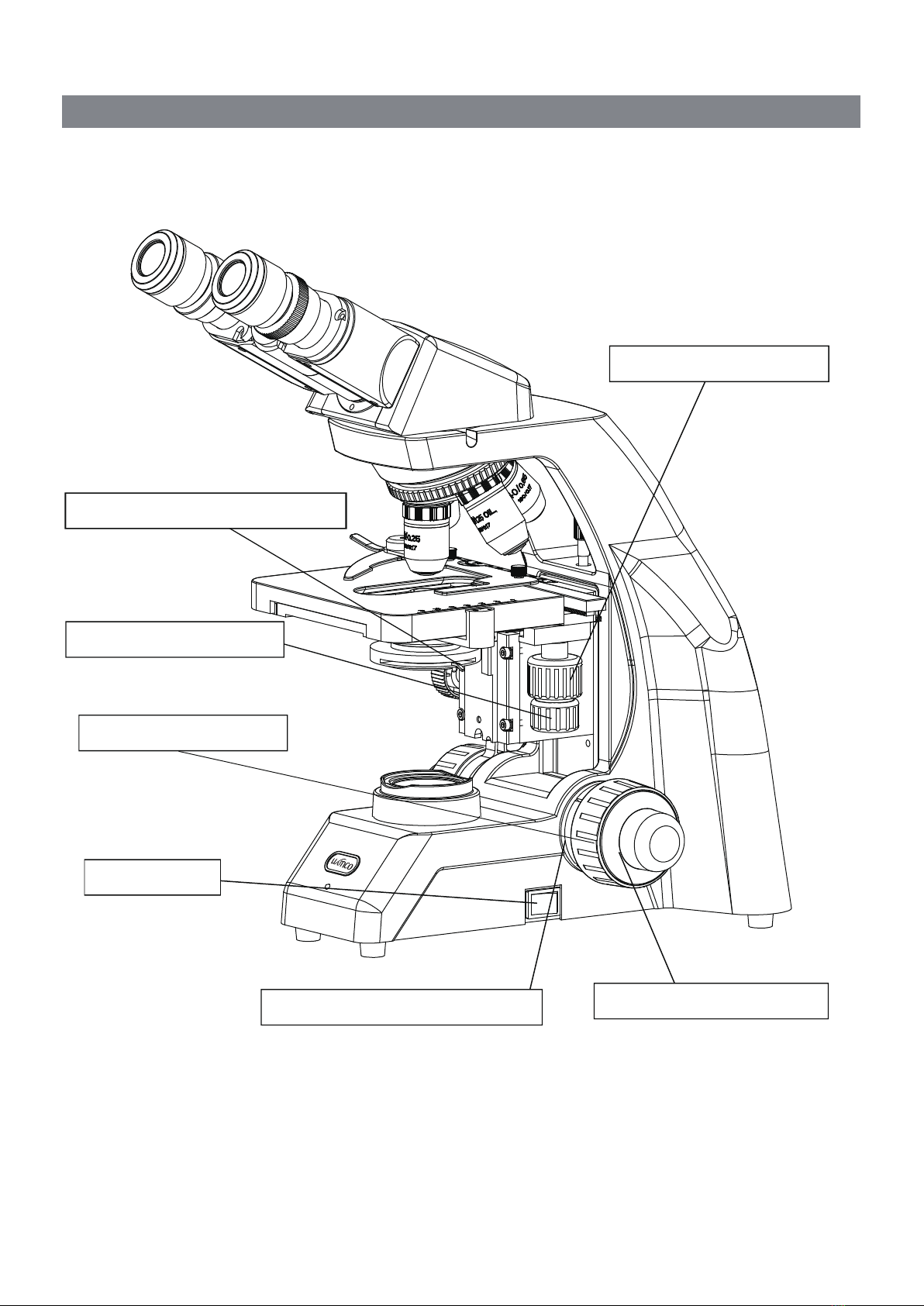
Fig.13
3. Adjustment and Operation
3.1 Adjustment set diagram
Portrait Adjustment Knob
Right Coarse Focus Knob
Lateral Adjustment Knob
Aperture Iris Diaphragm adjustment
Main Switch
Tension Adjustment Collar Right Fine Focus Knob
Table of contents
Other Llutico Microscope manuals


Popular Microscope manuals by other brands


VWR
VWR VisiScope 384 Series instruction manual

Nikon
Nikon ECLIPSE E200 POL instructions

Leica
Leica DI C800 User's manual & installation instructions

ThermoFisher Scientific
ThermoFisher Scientific Continuµm manual

ThermoFisher Scientific
ThermoFisher Scientific Continuµm manual

Olympus
Olympus SZ61 instructions