LNI NitroGen Series User manual

Table of contents
1 General informations................................................................................................................1
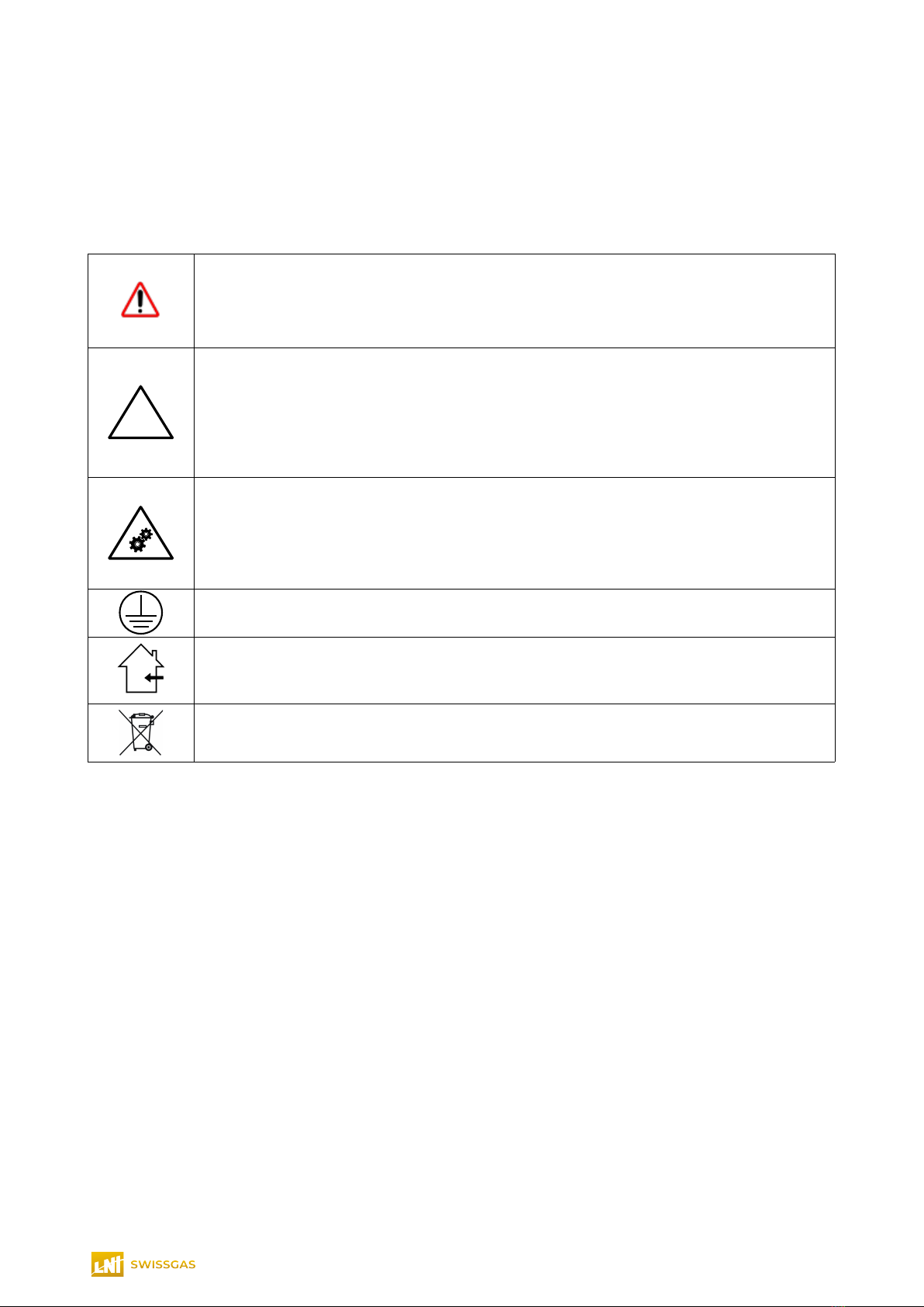
1.1 Symbols and terminology................................................................................................................1
1.2 General warnings............................................................................................................................2
1.3 Safety information...........................................................................................................................2
1.4 Intended use....................................................................................................................................3
1.5 Improper use...................................................................................................................................3
1.6 Reference directives........................................................................................................................3
1.7 Disposal...........................................................................................................................................3
2 Description of t e appliance.....................................................................................................4
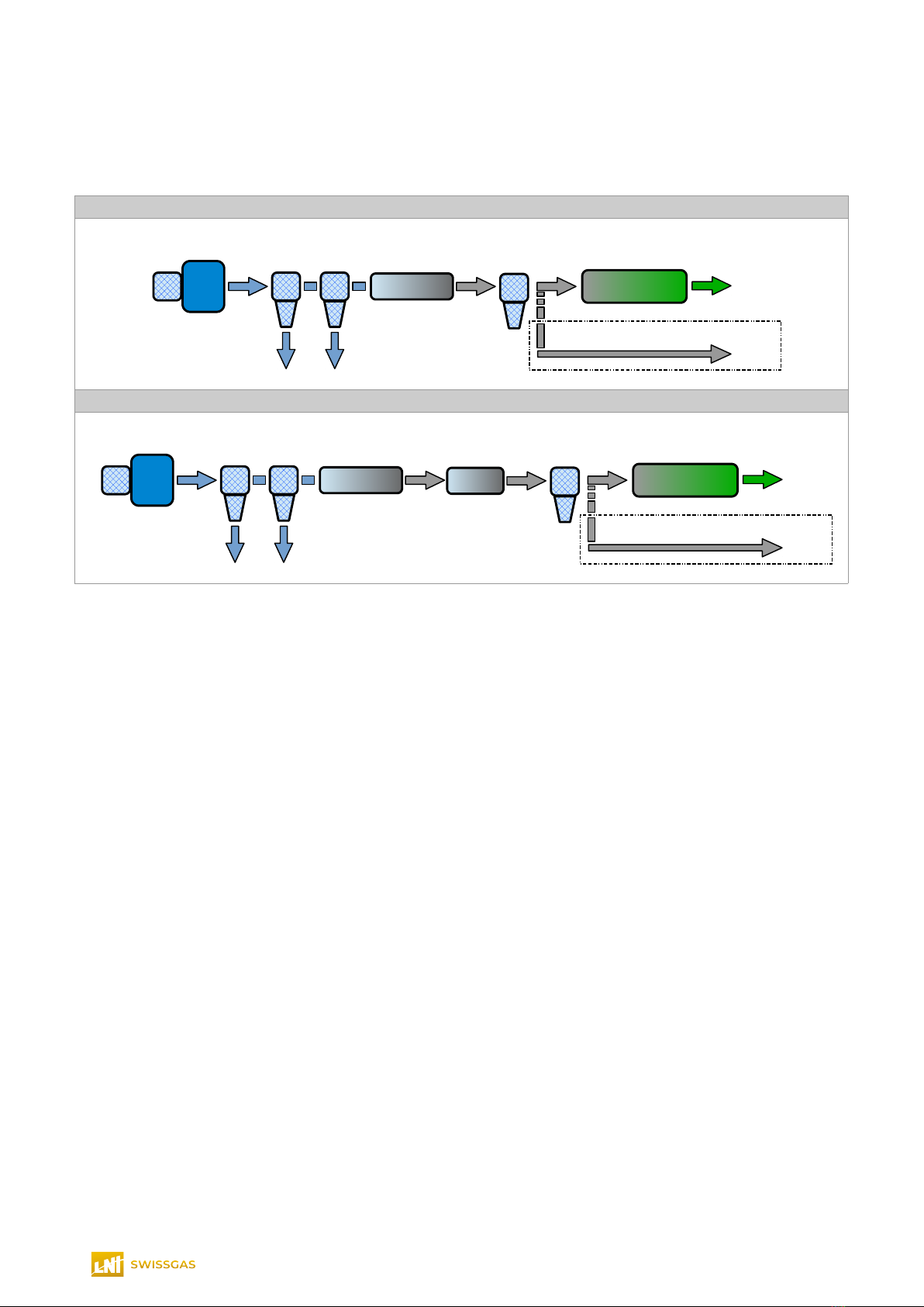
2.1 Operating principle..........................................................................................................................4
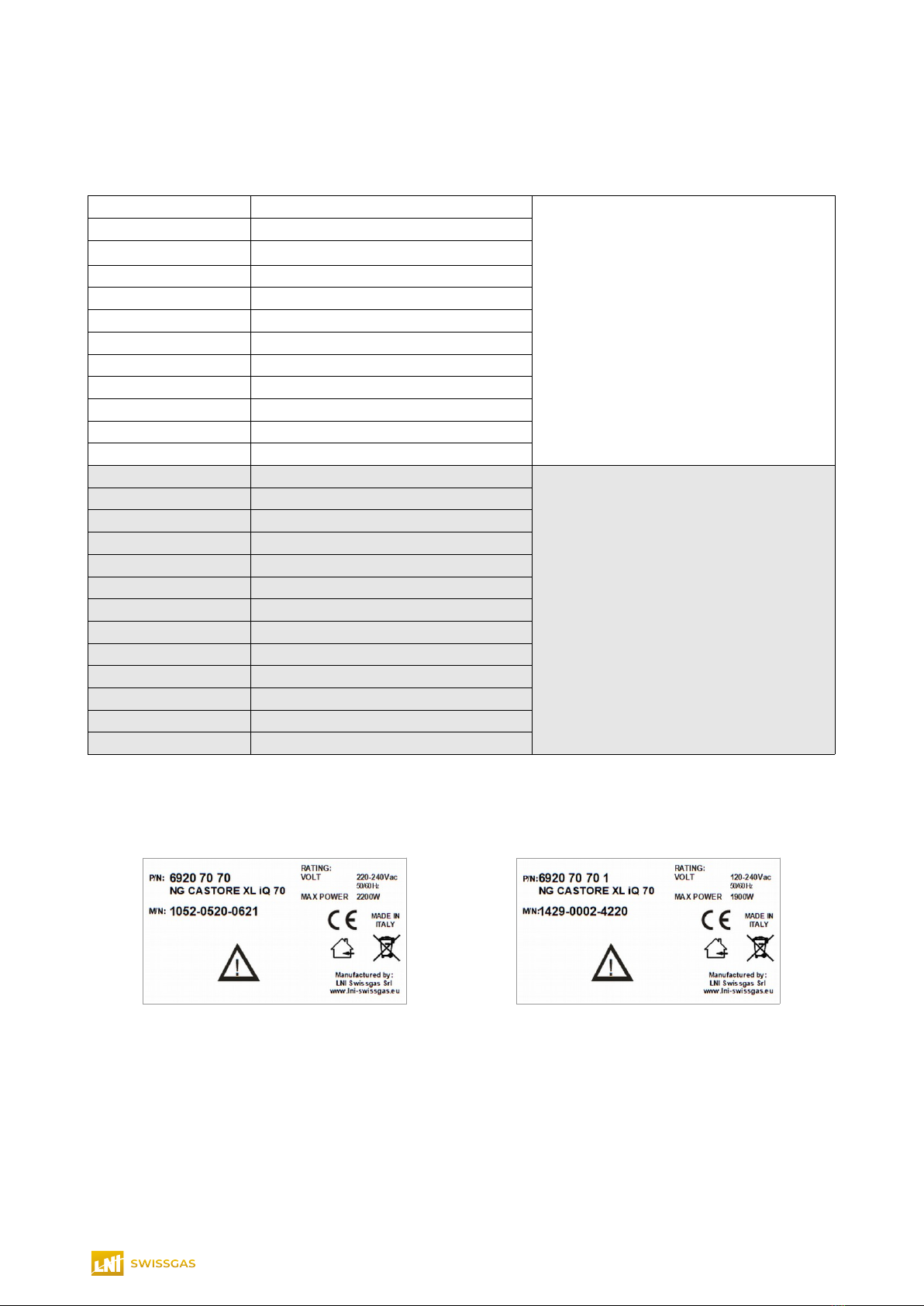
2.2 Identification of the models..............................................................................................................5
2.3 Technical specifications...................................................................................................................6
2.3.1 Operating and storage conditions...............................................................................................................6
2.3.2 NG CASTORE XL iQ 20..............................................................................................................................6
2.3.3 NG CASTORE XL iQ 40..............................................................................................................................7
2.3.4 NG CASTORE XL iQ 50..............................................................................................................................8
2.3.5 NG CASTORE XL iQ 70..............................................................................................................................9
2.3.6 NGA CASTORE XL iQ 20.40.....................................................................................................................10
2.3.7 NGA CASTORE XL iQ 40.40.....................................................................................................................11
2.3.8 NGA CASTORE XL iQ 20.60.....................................................................................................................12
2.3.9 NGA CASTORE XL iQ EVOQ...................................................................................................................13
2.3.10 NGA CASTORE XL iQ MP AES..............................................................................................................14
2.3.11 NGA CASTORE XL iQ QSight SS...........................................................................................................15
2.3.12 NGA CASTORE XL iQ QSight DS..........................................................................................................16
2.3.13 NGA CASTORE XL iQ SCIEX.................................................................................................................17
2.3.14 NGA CASTORE XL iQ SCIEX 7500........................................................................................................18
2.4 Weight and dimensions.................................................................................................................19
2.4.1 Weight........................................................................................................................................................19
2.4.2 Dimensions................................................................................................................................................19
2.5 Overview of the appliance.............................................................................................................20
3 Receiving t e appliance..........................................................................................................21
3.1 Packing list....................................................................................................................................21
4 Available accessories (not included, to be requested separately)......................................22
4.1 Purge tank – 6950.92.062.............................................................................................................22
4.2 Pressure regulators box................................................................................................................22
5 Installation............................................................................................................................... 24
5.1 Installation layout...........................................................................................................................24
5.2 Positioning.....................................................................................................................................25
5.3 Pneumatic connections.................................................................................................................26
5.4 Electrical connection.....................................................................................................................27
6 Commissioning....................................................................................................................... 28
6.1 Starting the appliance the first time...............................................................................................28
6.2 Shutting down................................................................................................................................29
6.3 Returning the appliance for service and/or repairs.......................................................................29
7 Operation................................................................................................................................. 30
7.1 User interface................................................................................................................................30
7.2 Summary screen...........................................................................................................................31
7.2.1 System status............................................................................................................................................32
7.3 Starting and stopping nitrogen production....................................................................................32
7.4 Serial communication and connections.........................................................................................33
7.4.1 Digital I/Os.................................................................................................................................................33
7.4.2 Auxiliary connections.................................................................................................................................33
7.5 Parallel Mode.................................................................................................................................34
7.5.1 Introduction................................................................................................................................................34
7.5.2 Kit Parallel system control box with LAN kit (P/N: 6920.71.60)...............................................................34
7.5.3 Electrical connection..................................................................................................................................35
7.5.4 Installation with multiple generators..........................................................................................................35
7.5.5 System ID setting......................................................................................................................................36
7.5.6 System status............................................................................................................................................36

7.5.7 Master flow controller................................................................................................................................36
7.5.8 Configuration.............................................................................................................................................37
8 Menu......................................................................................................................................... 38
8.1 Adjust Set Pressure.......................................................................................................................39
8.2 Setup.............................................................................................................................................40
8.2.1 Parameter..................................................................................................................................................40
8.2.2 List of user parameters..............................................................................................................................40
8.2.3 Auto Run....................................................................................................................................................41
8.2.4 Pressure Unit.............................................................................................................................................41
8.2.5 Temperature Unit.......................................................................................................................................42
8.2.6 Remote contact.........................................................................................................................................42
8.3 Date/Time Setting..........................................................................................................................43
8.4 Backlight Time...............................................................................................................................43
8.5 History...........................................................................................................................................43
8.6 Diagnostics....................................................................................................................................44
8.7 Counters........................................................................................................................................46
9 Maintenances........................................................................................................................... 47
9.1.1 Preventive checks and maintenances.......................................................................................................47
9.2 NG(A) CASTORE XL iQ (working @ 80% of its maximum power)...............................................48
9.2.1 Note:..........................................................................................................................................................48
9.3 Access for maintenances..............................................................................................................49
9.3.1 Replace the Compressor air intake filter and N2 stage filters (units without carbon column installed)...50
9.3.2 Replace the Compressor air intake filter and N2 stage filters (units with carbon column installed)........51
9.3.3 Replace the carbon filter column...............................................................................................................52
9.4 Service Menu.................................................................................................................................52
10 Alarms and pre-alarms..........................................................................................................53
10.1 Reset pre-alarm #5-Service 1.....................................................................................................53
Follow the same operations described to reset the pre-alarm for Service 2 and Service 3..................53
10.2 Pre-alarms...................................................................................................................................54
10.3 Alarms..........................................................................................................................................56
11 How to request service.........................................................................................................57

1 General informations
1.1 Symbols and terminology
In the unit and in this manual are used some symbols to signal to the user one or more information.
Consult the user manual in all cases where the following symbols is marked on the equipment in order to find
out the nature of the potential hazard and any actions which have to be taken to avoid them.
Warning/caution.
Used in this manual to signal to pay particular attention to the operation in progress.
Failure to heed the warnings/cautions given may cause severe personal injuries and
material damage.
In this manual with this symbol there is a message showing the relative type of warning.
!
Warning/caution – unit labels.
When present in the generator in a certain place it signals a specific warning:
•data plate – to avoid electrical problems and for correct power supply of the unit
the general line must be sized in accordance with the data indicated (power
supply frequency and power).
•label with fuses rating – when replacing one or more fuses use only fuse/s that
comply with the specifications indicated.
Warning – Mec anical moving parts.
Indicated in the unit (on the compressor protective panel) to signal to pay particular
attention to the mechanical moving parts contained in the unit.
To avoid any possible personal damage/injuring be sure the unit is completely stopped
and electrically isolated before performing any service operations involving the internal
parts of the unit.
Protective conductor terminal.
Indicated in the unit to signal the presence of the protective conductor terminal
Indoor facilities.
Used to indicate the unit has been engineered to be stored and used only in indoor
facilities
Disposal.
Used to indicate to not dispose the unit as a common material but only following the
defined local regulations
This manual contains also technical terminology. The meaning of specific terms that may not be commonly
understood are described below.
Set point : defines a certain value that the system aims to reach
Operating manual NG(A) CASTO E XL iQ 1

1.2 General warnings
Before using t e appliance, users must read and understand t e contents of every section of t is
manual
The descriptions drawings and photographs contained in this manual are purely indicative and in some
cases may not reflect the actual appliance purchased
The transfer to third parties and reproduction of all or part of this manual is prohibited without the written
authorisation of the manufacturer and/or the reseller
The manufacturer and/or the reseller accepts no liability for injuries production downtime or other
expenses due to errors or omissions in this manual
This manual is an integral part of the appliance; consequently it must be kept throughout the life of the
appliance in a safe place that is accessible and known to all users of the appliance
The manufacturer reserves the right to make any modifications that it considers useful for the
improvement of its products at any time
Failure to heed the warnings given in this manual may cause severe personal injuries and material
damage
Contact the manufacturer and/or the reseller if you find a problem that you cannot solve with this manual.
1.3 Safety information
Nitrogen build-up may lead to a lack of oxygen and t erefore create t e risk of asp yxia.
Do not use the appliance until the safety information and instructions in this manual have been read and
understood.
Using the appliance in a manner not specified in this document may compromise the protection provided
by the generator and could lead to an unexpected release of pressure which may cause serious
personal injury or damage
When handling installing or operating this appliance personnel should adopt correct procedures and
comply with all local health and safety regulations and legal safety requirements.
Only competent and suitably trained people may carry out the commissioning maintenance and repair of
the appliance
Ensure equipment is electrically isolated and depressurised before performing any routine maintenance
specified inside this user manual. Most accidents that occur during the operation and maintenance of
machines are the result of failure to comply with basic safety procedures.
It is impossible to anticipate every possible circumstance t at may constitute a potential danger. T e
warnings in t is manual cover t e most known potential dangers.
Operating manual NG(A) CASTO E XL iQ 2

1.4 Intended use
The nitrogen generator is designed to produce nitrogen for laboratory use. The appliance must only be used
for this purpose in compliance with the specifications and instructions described in this manual. In particular
special attention must be paid to the following warnings:
Do not use the appliance outdoors
Do not use the appliance in temperature and humidity conditions outside of the limits specified for
operation (see 2.3)
Use a source of air with suitable characteristics (see 2.3.6)
Do not use the appliance in rooms with aggressive and polluting atmospheres
Make sure that the room where the appliance will be installed has suitable ventilation
Unplug the appliance from the mains power supply before accessing the inside of the appliance
Only use the original spare parts specified in this manual
1.5 Improper use
Improper use of the appliance is considered as the failure to observe the data on the rating plate the
technical and safety specifications indicated in this manual and the general standards in force
Improper use of the appliance may involve risks for the user
The appliance must only be repaired or serviced by the manufacturer and/or reseller’s Technical Service
The appliance must under no circumstances be modified or tampered with to avoid creating situations of
danger in which case the manufacturer declines all liability for any resulting damage
The manufacturer and/or reseller are in no way liable for any damage due to improper use of the
appliance.
1.6 Reference directives
The requirements of the following directives and technical standards have been applied during the design
and construction of the appliance described in this manual:
•Directive 2014/35/UE (Low voltage directive);
•Directive 2014/30/UE (Electromagnetic compatibility);
•Directive 2011/65/CEE (RoHS);
•Directive 2012/19/UE on waste disposal (Waste Electrical and Electronic Equipment – WEEE);
1.7 Disposal
In relation to European Directive 2012/19/UE (WEEE) disposal of the appliance is regulated by the following
requirements:
•Waste Electrical and Electronic Equipment (WEEE) cannot be disposed of as municipal waste.
Public or private waste collection systems must be used in accordance with local regulations
•The appliance can be returned to the reseller at the end of its working life when buying a new
appliance
•The appliance may contain dangerous substances: improper use or incorrect disposal of such
substances may cause damage to human health and the environment
•In the event of illegal disposal of waste electrical and electronic equipment the penalties are defined
by local waste disposal regulations.
Operating manual NG(A) CASTO E XL iQ 3

2 Description of t e appliance
2.1 Operating principle
NG(A) CASTORE XL iQ
Inlet lter
+
Compressor
Filter
A
Membrane
dryer
N2
membrane
N2
OUTLET
DryAir
OUTLET
urge
Filter
B
Filter
C
NG(A) CASTORE XL iQ with optional carbon filter column 6920.71.80
Inlet lter
+
Compressor
Membrane
dryer
N2
membrane
N2
OUTLET
DryAir
OUTLET
urge
Op$on
6920.71.80
Filter
A
Filter
B
Filter
D
The nitrogen generators described in this manual thanks to its built in scroll-compressor are able to provide
by itself the necessary quantity of compressed air to supply the N2 Membrane section and produce a stable
and safe flow of pure nitrogen at a setted pressure.
Units NGA CASTORE XL iQ also provide a source of Dry air.
The appliances can be used in laboratories and/or light industrial environments.
Operating manual NG(A) CASTO E XL iQ 4

2.2 Identification of t e models
This manual refers to the following models of the appliance:
6920.70.20 NG CASTORE XL iQ 20
220-240 VAC models
6920.70.40 NG CASTORE XL iQ 40
6920.70.70 NG CASTORE XL iQ 70
6920.70.21 NGA CASTORE XL iQ 20.40
6920.70.41 NGA CASTORE XL iQ 40.40
6920.70.22 NGA CASTORE XL iQ 20.60
6920.70.45 NGA CASTORE XL iQ EVOQ
6920.70.42 NGA CASTORE XL iQ MP AES
6920.70.43 NGA CASTORE XL iQ SCIEX
6920.70.44 NGA CASTORE XL iQ SCIEX 7500
6920.70.23 NGA CASTORE XL iQ QSig t SS
6920.70.24 NGA CASTORE XL iQ QSig t DS
6920.70.20.1 NG CASTORE XL iQ 20
FULL ANGE power supply voltage
(115-240 VAC)
6920.70.40.1 NG CASTORE XL iQ 40
6920.70.50.1 NG CASTORE XL iQ 50
6920.70.70.1 NG CASTORE XL iQ 70
6920.70.21.1 NGA CASTORE XL iQ 20.40
6920.70.41.1 NGA CASTORE XL iQ 40.40
6920.70.22.1 NGA CASTORE XL iQ 20.60
6920.70.45.1 NGA CASTORE XL iQ EVOQ
6920.70.42.1 NGA CASTORE XL iQ MP AES
6920.70.43.1 NGA CASTORE XL iQ SCIEX
6920.70.44.1 NGA CASTORE XL iQ SCIEX 7500
6920.70.23.1 NGA CASTORE XL iQ QSig t SS
6920.70.24.1 NGA CASTORE XL iQ QSig t DS
Some parts of this manual refer to just one or some of these models.
The model is identified on the product label applied to the rear of the appliance as shown in the figure below:
Identification label
Figure 1: Identification label
Operating manual NG(A) CASTO E XL iQ 5

2.3 Tec nical specifications
2.3.1 Operating and storage conditions
Operating and storage conditions
Operating temperature 5-35°C (41-95°F)
Storage temperature 1-40°C (33.8-104°F)
Humidity (max non-condensing) 80% [5-35°C (41-95°F)]
Noise < 50dB(A)
Over-voltage category II
Pollution degree rating 2 (with no aromatic compounds)
IP IP20
Altitude < 2000m
Table 1: General technical specifications
2.3.2 NG CASTORE XL iQ 20
NG CASTORE XL iQ 20
Models: 6920.70.20 - .1
N2 outlet
Flow rate (Max) 20 l/min
Outlet pressure (Max) 9 Bar (130 psi)
Nitrogen purity LCMS grade (up to 99.9%*1)
Nitrogen for collision cell *2 200 cc/min @ 99.9999%*3 with option 6920.71.90
Communication
LCD with touch screen Standard
RS485 Standard
RS232 For service
General data
Power supply voltage (min-Max) 220-240 Vac ±10% 50/60 Hz 115-240 Vac ±10% 50/60 Hz
Connection type IEC C20
Nominal power (Max) 1.4 KW 1.3 KW
Net weight 175 kg 185 kg
Noise level < 45 dB
Unit fuse F1 (10x38mm) 15A (600Vac – T – class CC) 15A (600Vac – T – class CC)
Unit fuse F2 (10x38mm) 6A (600Vac – T – class CC) -
Inverter protection fuses F3 - F4
(10x38mm) - 15A (300Vdc – T – class CC)
Main-board fuse F5 (5x20mm) 3.15A (250Vac – T – L / 35 A)
Heat value (BTU) 4800 4440
Dimensions (W x D x H) 59 x 92 x 73 cm
Connections
N2 outlet port ¼" BSPP female
N2 UHP outlet port ¼" BSPP female
Drain port ¼" BSPP female
*1 The purity refers to the residual oxygen depends on flow and working pressure
*2 Optional
*3 The purity refers to the residual oxygen
Operating manual NG(A) CASTO E XL iQ 6

2.3.3 NG CASTORE XL iQ 40
NG CASTORE XL iQ 40
Models: 6920.70.40 - .1
N2 outlet
Flow rate (Max) 40 l/min
Outlet pressure (Max) 8 Bar (116 psi)
Nitrogen purity LCMS grade (up to 99.9%*1)
Nitrogen for collision cell *2 200 cc/min @ 99.9999%*3 with option 6920.71.90
Communication
LCD with touch screen Standard
RS485 Standard
RS232 For service
General data
Power supply voltage (min-Max) 220-240 Vac ±10% 50/60 Hz 115-240 Vac ±10% 50/60 Hz
Connection type IEC C20
Nominal power (Max) 1.8 KW 1.5 KW
Net weight 175 kg 185 kg
Noise level < 45 dB
Unit fuse F1 (10x38mm) 15A (600Vac – T – class CC) 15A (600Vac – T – class CC)
Unit fuse F2 (10x38mm) 6A (600Vac – T – class CC) -
Inverter protection fuses F3 - F4
(10x38mm) - 15A (300Vdc – T – class CC)
Main-board fuse F5 (5x20mm) 3.15A (250Vac – T – L / 35 A)
Heat value (BTU) 6150 5130
Dimensions (W x D x H) 59 x 92 x 73 cm
Connections
N2 outlet port ¼" BSPP female
N2 UHP outlet port ¼" BSPP female
Drain port ¼" BSPP female
*1 The purity refers to the residual oxygen depends on flow and working pressure
*2 Optional
*3 The purity refers to the residual oxygen
Operating manual NG(A) CASTO E XL iQ 7

2.3.4 NG CASTORE XL iQ 50
NG CASTORE XL iQ 50
Models: 6920.70.50 - .1
N2 outlet
Flow rate (Max) 50 l/min
Outlet pressure (Max) 8 Bar (116 psi)
Nitrogen purity LCMS grade (up to 99.9%*1)
Nitrogen for collision cell *2 200 cc/min @ 99.9999%*3 with option 6920.71.90
Communication
LCD with touch screen Standard
RS485 Standard
RS232 For service
General data
Power supply voltage (min-Max) - 115-240 Vac ±10% 50/60 Hz
Connection type IEC C20
Nominal power (Max) - 1.5 KW
Net weight - 185 kg
Noise level < 50 dB
Unit fuse F1 (10x38mm) - 15A (600Vac – T – class CC)
Unit fuse F2 (10x38mm) 6A (600Vac – T – class CC) -
Inverter protection fuses F3 - F4
(10x38mm) - 15A (300Vdc – T – class CC)
Main-board fuse F5 (5x20mm) 3.15A (250Vac – T – L / 35 A)
Heat value (BTU) - 5130
Dimensions (W x D x H) 59 x 92 x 73 cm
Connections
N2 outlet port ¼" BSPP female
N2 UHP outlet port ¼" BSPP female
Drain port ¼" BSPP female
*1 The purity refers to the residual oxygen depends on flow and working pressure
*2 Optional
*3 The purity refers to the residual oxygen
Operating manual NG(A) CASTO E XL iQ 8

2.3.5 NG CASTORE XL iQ 70
NG CASTORE XL iQ 70
Models: 6920.70.70 - .1
N2 outlet
Flow rate (Max) 70 l/min
Outlet pressure (Max) 8 Bar
Nitrogen purity LCMS grade (up to 99.9%*1)
Nitrogen for collision cell *2 200 cc/min @ 99.9999%*3 with option 6920.71.90
Communication
LCD with touch screen Standard
RS485 Standard
RS232 For service
General data
Power supply voltage (min-Max) 220-240 Vac ±10% 50/60 Hz 115-240 Vac ±10% 50/60 Hz
Connection type IEC C20
Nominal power (Max) 2.2 KW 1.9 KW
Net weight 175 kg 185 kg
Noise level < 50 dB
Unit fuse F1 (10x38mm) 15A (600Vac – T – class CC) 20A (600Vac – T – class CC)
Unit fuse F2 (10x38mm) 6A (600Vac – T – class CC) -
Inverter protection fuses F3 - F4
(10x38mm) - 15A (300Vdc – T – class CC)
Main-board fuse F5 (5x20mm) 3.15A (250Vac – T – L / 35 A)
Heat value (BTU) 7510 6500
Dimensions (W x D x H) 59 x 92 x 73 cm
Connections
N2 outlet port ¼" BSPP female
N2 UHP outlet port ¼" BSPP female
Drain port ¼" BSPP female
*1 The purity refers to the residual oxygen depends on flow and working pressure
*2 Optional
*3 The purity refers to the residual oxygen
Operating manual NG(A) CASTO E XL iQ 9

2.3.6 NGA CASTORE XL iQ 20.40
NGA CASTORE XL iQ 20.40
Models: 6920.70.21 - .1
N2 outlet
Flow rate (Max) 20 l/min
Outlet pressure (Max) 8 Bar (116 psi)
Nitrogen purity LCMS grade (up to 99.9%*1)
Nitrogen for collision cell*2 200 cc/min @ 99.9999%*3 with option 6920.71.90
Dry Air outlet
Flow rate (Max) 40 l/min
Outlet pressure (Max) 8 Bar (116 psi)
Dew point*4 < -40°C (- 40°F)
Communication
LCD with touch screen Standard
RS485 Standard
RS232 For service
General data
Power supply voltage (min-Max) 220-240 Vac ±10% 50/60 Hz 115-240 Vac ±10% 50/60 Hz
Connection type IEC C20
Nominal power (Max) 1.8 KW 1.5 KW
Net weight 180 kg 190 kg
Noise level < 50 dB
Unit fuse F1 (10x38mm) 15A (600Vac – T – class CC) 15A (600Vac – T – class CC)
Unit fuse F2 (10x38mm) 6A (600Vac – T – class CC) -
Inverter protection fuses F3 - F4
(10x38mm) - 15A (300Vdc – T – class CC)
Main-board fuse F5 (5x20mm) 3.15A (250Vac – T – L / 35 A)
Heat value (BTU) 6150 5130
Dimensions (W x D x H) 59 x 92 x 73 cm
Connections
N2 outlet port ¼" BSPP female
Dry Air outlet port ¼" BSPP female
N2 UHP outlet port ¼" BSPP female
Drain port ¼" BSPP female
*1 The purity refers to the residual oxygen depends on flow and working pressure
*2 Optional
*3 The purity refers to the residual oxygen
*4 Atmospheric Dew Point (ADP)
Operating manual NG(A) CASTO E XL iQ 10

2.3.7 NGA CASTORE XL iQ 40.40
NGA CASTORE XL iQ 40.40
Models: 6920.70.41 - .1
N2 outlet
Flow rate (Max) 40 l/min
Outlet pressure (Max) 8 Bar (116 psi)
Nitrogen purity LCMS grade (up to 99.9%*1)
Nitrogen for collision cell*2 200 cc/min @ 99.9999%*3 with option 6920.71.90
Dry Air outlet
Flow rate (Max) 40 l/min
Outlet pressure (Max) 8 Bar (116 psi)
Dew point*4 < -40°C (- 40°F)
Communication
LCD with touch screen Standard
RS485 Standard
RS232 For service
General data
Power supply voltage (min-Max) 220-240 Vac ±10% 50/60 Hz 115-240 Vac ±10% 50/60 Hz
Connection type IEC C20
Nominal power (Max) 2.0 KW 1.7 KW
Net weight 180 kg 190 kg
Noise level < 50 dB
Unit fuse F1 (10x38mm) 15A (600Vac – T – class CC) 20A (600Vac – T – class CC)
Unit fuse F2 (10x38mm) 6A (600Vac – T – class CC) -
Inverter protection fuses F3 - F4
(10x38mm) - 15A (300Vdc – T – class CC)
Main-board fuse F5 (5x20mm) 3.15A (250Vac – T – L / 35 A)
Heat value (BTU) 6830 5800
Dimensions (W x D x H) 59 x 92 x 73 cm
Connections
N2 outlet port ¼" BSPP female
Dry Air outlet port ¼" BSPP female
N2 UHP outlet port ¼" BSPP female
Drain port ¼" BSPP female
*1 The purity refers to the residual oxygen depends on flow and working pressure
*2 Optional
*3 The purity refers to the residual oxygen
*4 Atmospheric Dew Point (ADP)
Operating manual NG(A) CASTO E XL iQ 11

2.3.8 NGA CASTORE XL iQ 20.60
NGA CASTORE XL iQ 20.60
Models: 6920.70.22 - .1
N2 outlet
Flow rate (Max) 20 l/min
Outlet pressure (Max) 8 Bar (116 psi)
Nitrogen purity LCMS grade (up to 99.9%*1)
Nitrogen for collision cell*2 200 cc/min @ 99.9999%*3 with option 6920.71.90
Dry Air outlet
Flow rate (Max) 60 l/min
Outlet pressure (Max) 8 Bar (116 psi)
Dew point*4 < -40°C (- 40°F)
Communication
LCD with touch screen Standard
RS485 Standard
RS232 For service
General data
Power supply voltage (min-Max) 220-240 Vac ±10% 50/60 Hz 115-240 Vac ±10% 50/60 Hz
Connection type IEC C20
Nominal power (Max) 2.0 KW 1.7 KW
Net weight 180 kg 190 kg
Noise level < 50 dB
Unit fuse F1 (10x38mm) 15A (600Vac – T – class CC) 20A (600Vac – T – class CC)
Unit fuse F2 (10x38mm) 6A (600Vac – T – class CC) -
Inverter protection fuses F3 - F4
(10x38mm) - 15A (300Vdc – T – class CC)
Main-board fuse F5 (5x20mm) 3.15A (250Vac – T – L / 35 A)
Heat value (BTU) 6830 5800
Dimensions (W x D x H) 59 x 92 x 73 cm
Connections
N2 outlet port ¼" BSPP female
Dry Air outlet port ¼" BSPP female
N2 UHP outlet port ¼" BSPP female
Drain port ¼" BSPP female
*1 The purity refers to the residual oxygen depends on flow and working pressure
*2 Optional
*3 The purity refers to the residual oxygen
*4 Atmospheric Dew Point (ADP)
Operating manual NG(A) CASTO E XL iQ 12

2.3.9 NGA CASTORE XL iQ EVOQ
NGA CASTORE XL iQ EVOQ
Models: 6920.70.45 - .1
N2 outlet
Flow rate (Max) 32 l/min
Outlet pressure (Max) 6.5 Bar (94 psi)
Nitrogen purity LCMS grade (up to 99.9%*1)
O2 Residual < 500ppm @ 10 l/min
< 0.5% @ 30 l/min
Dry Air outlet
Flow rate (Max) 50 l/min
Outlet pressure (Max) 6.5 Bar (94 psi)
Dew point*2 < -30°C (- 22°F)
Communication
LCD with touch screen Standard
RS485 Standard
RS232 For service
General data
Power supply voltage (min-Max) 220-240 Vac ±10% 50/60 Hz 115-240 Vac ±10% 50/60 Hz
Connection type IEC C20
Nominal power (Max) 1.9 KW 1.7 KW
Net weight 180 kg 190 kg
Noise level < 50 dB
Unit fuse F1 (10x38mm) 15A (600Vac – T – class CC) 20A (600Vac – T – class CC)
Unit fuse F2 (10x38mm) 6A (600Vac – T – class CC) -
Inverter protection fuses F3 - F4
(10x38mm) - 15A (300Vdc – T – class CC)
Main-board fuse F5 (5x20mm) 3.15A (250Vac – T – L / 35 A)
Heat value (BTU) 6500 5800
Dimensions (W x D x H) 59 x 92 x 73 cm
Connections
N2 outlet port 1/4” SWAGELOK compatible
Dry Air outlet port 1/4” SWAGELOK compatible
N2 UHP outlet port -
Drain port 1/4” BSPP female
*1 The purity refers to the residual oxygen depends on flow and working pressure
*2 Atmospheric Dew Point (ADP)
Operating manual NG(A) CASTO E XL iQ 13

2.3.10 NGA CASTORE XL iQ MP AES
NGA CASTORE XL iQ MP AES
Models: 6920.70.42 - .1
N2 outlet
Flow rate (Max) 25 l/min
Outlet pressure (Max) 6.5 Bar (94 psi)
Nitrogen purity LCMS grade (up to 99.9%*1)
O2 Residual < 500ppm @ 10 l/min
< 0.5% @ 30 l/min
Dry Air outlet
Flow rate (Max) 40 l/min
Outlet pressure (Max) 6.5 Bar (94 psi)
Dew point*2 < -30°C (- 22°F)
Communication
LCD with touch screen Standard
RS485 Standard
RS232 For service
General data
Power supply voltage (min-Max) 220-240 Vac ±10% 50/60 Hz 115-240 Vac ±10% 50/60 Hz
Connection type IEC C20
Nominal power (Max) 2.0 KW 1.9 KW
Net weight 180 kg 190 kg
Noise level < 50 dB
Unit fuse F1 (10x38mm) 15A (600Vac – T – class CC) 20A (600Vac – T – class CC)
Unit fuse F2 (10x38mm) 6A (600Vac – T – class CC) -
Inverter protection fuses F3 - F4
(10x38mm) - 15A (300Vdc – T – class CC)
Main-board fuse F5 (5x20mm) 3.15A (250Vac – T – L / 35 A)
Heat value (BTU) 6850 6500
Dimensions (W x D x H) 59 x 92 x 73 cm
Connections
N2 outlet port 1/4” SWAGELOK compatible
Dry Air outlet port 1/4” SWAGELOK compatible
N2 UHP outlet port -
Drain port 1/4” BSPP female
*1 The purity refers to the residual oxygen depends on flow and working pressure
*2 Atmospheric Dew Point (ADP)
Operating manual NG(A) CASTO E XL iQ 14

2.3.11 NGA CASTORE XL iQ QSig t SS
NGA CASTORE XL iQ QSig t SS
Models: 6920.70.23 - .1
N2 outlet
Flow rate (Max) 16 l/min
Outlet pressure (Max) 8 Bar (116 psi)
Nitrogen purity LCMS grade (up to 99.9%)
Dew point*1 < -60°C (- 76°F)
Dry Air outlet
Flow rate (Max) 34 l/min
Outlet pressure (Max) 8 Bar (116 psi)
Dew point*1 < -30°C (- 22°F)
Communication
LCD with touch screen Standard
RS485 Standard
RS232 For service
General data
Power supply voltage (min-Max) 220-240 Vac ±10% 50/60 Hz 115-240 Vac ±10% 50/60 Hz
Connection type IEC C20
Nominal power (Max) 1.7 KW 1.5 KW
Net weight 180 kg 190 kg
Noise level < 50 dB
Unit fuse F1 (10x38mm) 15A (600Vac – T – class CC) 15A (600Vac – T – class CC)
Unit fuse F2 (10x38mm) 6A (600Vac – T – class CC) -
Inverter protection fuses F3 - F4
(10x38mm) - 15A (300Vdc – T – class CC)
Main-board fuse F5 (5x20mm) 3.15A (250Vac – T – L / 35 A)
Heat value (BTU) 5800 5130
Dimensions (W x D x H) 59 x 92 x 73 cm
Connections
N2 outlet port 1/4” BSPP female
Dry Air outlet port 1/4” BSPP female
N2 UHP outlet port -
Drain port 1/4” BSPP female
*1 – Atmospheric Dew Point (ADP)
OTE:
Minimum environment temperature > 10°C (>50°F) to have best performance on O2 residual content
Operating manual NG(A) CASTO E XL iQ 15

2.3.12 NGA CASTORE XL iQ QSig t DS
NGA CASTORE XL iQ QSig t DS
Models: 6920.70.24 - .1
N2 outlet
Flow rate (Max) 16 l/min
Outlet pressure (Max) 8 Bar (116 psi)
Nitrogen purity LCMS grade (up to 99.9%)
Dew point*1 < -60°C (- 76°F)
Dry Air outlet
Flow rate (Max) 67 l/min
Outlet pressure (Max) 8 Bar (116 psi)
Dew point*1 < -20°C (- 4°F)
Communication
LCD with touch screen Standard
RS485 Standard
RS232 For service
General data
Power supply voltage (min-Max) 220-240 Vac ±10% 50/60 Hz 115-240 Vac ±10% 50/60 Hz
Connection type IEC C20
Nominal power (Max) 1.9 KW 1.7 KW
Net weight 180 kg 190 kg
Noise level < 50 dB
Unit fuse F1 (10x38mm) 15A (600Vac – T – class CC) 20A (600Vac – T – class CC)
Unit fuse F2 (10x38mm) 6A (600Vac – T – class CC) -
Inverter protection fuses F3 - F4
(10x38mm) - 15A (300Vdc – T – class CC)
Main-board fuse F5 (5x20mm) 3.15A (250Vac – T – L / 35 A)
Heat value (BTU) 6500 5800
Dimensions (W x D x H) 59 x 92 x 73 cm
Connections
N2 outlet port 1/4” BSPP female
Dry Air outlet port 1/4” BSPP female
N2 UHP outlet port -
Drain port 1/4” BSPP female
*1 – Atmospheric Dew Point (ADP)
OTE:
Minimum environment temperature > 10°C (>50°F) to have best performance on O2 residual content
Operating manual NG(A) CASTO E XL iQ 16

2.3.13 NGA CASTORE XL iQ SCIEX
NGA CASTORE XL iQ SCIEX
Models: 6920.70.43 - .1
N2 outlet
Flow rate (Max) 20 l/min
Outlet pressure (Max) 8 Bar (116 psi)
Nitrogen purity LCMS grade (up to 99.9%)
Dew point*1 < -60°C (- 76°F)
Dry Air outlet 1
Flow rate (Max) 30 l/min
Outlet pressure (Max) 7 Bar (101 psi)
Dew point*1 < -40°C (- 40°F)
Dry Air outlet 2
Flow rate (Max) 30 l/min
Outlet pressure (Max) 4 Bar (58 psi)
Dew point*1 < -40°C (- 40°F)
Communication
LCD with touch screen Standard
RS485 Standard
RS232 For service
General data
Power supply voltage (min-Max) 220-240 Vac ±10% 50/60 Hz 115-240 Vac ±10% 50/60 Hz
Connection type IEC C20
Nominal power (Max) 1.9 KW 1.7 KW
Net weight 180 kg 190 kg
Noise level < 50 dB
Unit fuse F1 (10x38mm) 15A (600Vac – T – class CC) 20A (600Vac – T – class CC)
Unit fuse F2 (10x38mm) 6A (600Vac – T – class CC) -
Inverter protection fuses F3 - F4
(10x38mm) - 15A (300Vdc – T – class CC)
Main-board fuse F5 (5x20mm) 3.15A (250Vac – T – L / 35 A)
Heat value (BTU) 6500 5800
Dimensions (W x D x H) 59 x 92 x 73 cm
Connections
N2 outlet port 1/4” SWAGELOK compatible
Dry Air outlet port 1/4” SWAGELOK compatible
N2 UHP outlet port -
Drain port 1/4” BSPP female
*1 – Atmospheric Dew Point (ADP)
OTE:
Minimum environment temperature > 10°C (>50°F) to have best performance on O2 residual content
Operating manual NG(A) CASTO E XL iQ 17
Other manuals for NitroGen Series
1
This manual suits for next models
13
Table of contents
Other LNI Portable Generator manuals